


Choosing an Electrical Switch
More
14 mm Panel-Mount Push-Button Switches


These switches are rated IP67 for protection from dust and temporary submersion.
Note: Illuminated switches include a bulb. If wiring the switch and the bulb to the same circuit, the circuit voltage must not exceed bulb voltage.
IP69K rated switches withstand high-pressure, high-temperature washdowns.
Wire Leads | |||||||||||||||
|---|---|---|---|---|---|---|---|---|---|---|---|---|---|---|---|
| No. of Circuits Controlled | Switch Starting Position | Switch Action | No. of Terminals | Industry Designation | Switching Current @ Voltage | Max. Voltage | Dia. | Ht. | Wd. | Dp. Behind Panel | Choose an Actuator Color | No. of | Lg. | Each | |
Metal Base with Wire Leads | |||||||||||||||
Round (IP67) | |||||||||||||||
| 1 | 1 Off (Normally Open) | Springs Back (Momentary) | 2 | SPST-NO | 0.5 A @ 48 V AC, 0.2 A @ 50 V DC | 50V DC 250V AC | 11/16" | __ | __ | 1" | 2 | 19" | 0000000 | 000000 | |
Round—Illuminated (IP67 and IP69K) | |||||||||||||||
| 1 | 1 Off (Normally Open) | Springs Back (Momentary) | 4 | SPST-NO | 0.5 A @ 48 V AC, 0.2 A @ 50 V AC | 50V DC 250V AC | 11/16" | __ | __ | 15/16" | 2 | 19" | 0000000 | 00000 | |
Square (IP67 and IP69K) | |||||||||||||||
| 1 | 1 Off (Normally Open) | Springs Back (Momentary) | 2 | SPST-NO | 0.5 A @ 48 V AC, 0.2 A @ 50 V AC | 50V DC 250V AC | __ | 11/16" | 11/16" | 15/16" | 2 | 19" | 0000000 | 00000 | |
Metal Base with Quick-Disconnect Terminals | |||||||||||||||
Round (IP67 and IP69K) | |||||||||||||||
| 1 | 1 Off (Normally Open) | Springs Back (Momentary) | 2 | SPST-NO | 0.5 A @ 48 V AC, 0.2 A @ 50 V AC | 50V DC 250V AC | 11/16" | __ | __ | 1/2" | __ | __ | 0000000 | 00000 | |
Metal Base with Tab Terminals | |||||||||||||||
Round (IP67) | |||||||||||||||
| 1 | 1 Off (Normally Open) | Springs Back (Momentary) | 2 | SPST-NO | 0.5 A @ 48 V AC, 0.2 A @ 50 V DC | 50V DC 250V AC | 11/16" | __ | __ | 11/16" | __ | __ | 0000000 | 00000 | |
Round—Illuminated (IP67 and IP69K) | |||||||||||||||
| 1 | 1 Off (Normally Open) | Springs Back (Momentary) | 4 | SPST-NO | 0.5 A @ 48 V AC, 0.2 A @ 50 V DC | 50V DC 250V AC | 11/16" | __ | __ | 11/16" | __ | __ | 0000000 | 00000 | |
Square (IP67) | |||||||||||||||
| 1 | 1 Off (Normally Open) | Springs Back (Momentary) | 2 | SPST-NO | 0.5 A @ 48 V AC, 0.2 A @ 50 V DC | 50V DC 250V AC | __ | 11/16" | 11/16" | 11/16" | __ | __ | 0000000 | 00000 | |
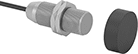
Magnetically Actuated Switches
These switches actuate when a magnet comes within sensing distance, and reset when the magnet moves away. They’re often used to detect when a door or window opens. Mount the switch in a stationary position, such as a door frame, and mount the magnet to a movable object, such as the door. They do not include a safety relay and cannot be used with safety-guard doors found on machinery.
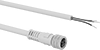
Switches with a plug connect to cables with a socket (sold separately), allowing you to quickly connect and disconnect the switch.
Switches with an LED status indicator let you visually confirm that it’s connected and whether it’s actuated.
IP65 rated switches protect against rinsing and dust. IP67 rated switches protect against temporary submersion, as well as dust and dirt. IP68 rated switches protect against washdowns and continuous submersion. Use IP69K rated switches in demanding environments, such as roadways.
Nano
M8 Plug
Micro
M12 Plug
Switches | ||||||||||||||||||
|---|---|---|---|---|---|---|---|---|---|---|---|---|---|---|---|---|---|---|
Wire Leads | Replacement Magnets | |||||||||||||||||
| No. of Circuits Controlled | Switch Starting Position | Industry Designation | Switching Current @ Voltage | Max. Voltage | Max. Sensing Distance | No. of | Lg., ft. | Dia. | Lg. | Wd. | Ht. | Mount. Thread Size | Environmental Rating | Each | Each | |||
Plastic Housing | ||||||||||||||||||
With Wire Leads and LED Status Indicator | ||||||||||||||||||
| J | 1 | 1 Off (Normally Open) | SPST-NO | 0.2 A @ 3 V DC | 30V DC | 2.36" | 3 | 6 | __ | 1.09" | 0.63" | 0.4" | __ | IP67 | 000000000 | 0000000 | 000000000 | 000000 |
With 3-Pole Nano M8 Plug and LED Status Indicator | ||||||||||||||||||
| J | 1 | 1 Off (Normally Open) | SPST-NO | 0.2 A @ 3 V DC | 30V DC | 2.36" | __ | __ | __ | 1.45" | 0.63" | 0.4" | __ | IP67 | 000000000 | 000000 | 000000000 | 00000 |
Stainless Steel Housing | ||||||||||||||||||
With Wire Leads and LED Status Indicator | ||||||||||||||||||
| K | 1 | 1 Off (Normally Open) | SPST-NO | 0.2 A @ 3 V DC | 30V DC | 2.36" | 3 | 6 | 0.31" | 1.96" | __ | __ | M8 | IP67 | 000000000 | 000000 | 000000000 | 00000 |
| K | 1 | 1 Off (Normally Open) | SPST-NO | 0.2 A @ 3 V DC | 30V DC | 2.36" | 3 | 6 | 0.47" | 1.96" | __ | __ | M12 | IP67 | 000000000 | 000000 | 000000000 | 00000 |
| K | 1 | 1 Off (Normally Open) | SPST-NO | 0.2 A @ 3 V DC | 30V DC | 2.75" | 3 | 6 | 0.71" | 1.96" | __ | __ | M18 | IP67 | 000000000 | 000000 | 000000000 | 00000 |
With 4-Pole Micro M12 Plug and LED Status Indicator | ||||||||||||||||||
| K | 1 | 1 Off (Normally Open) | SPST-NO | 0.2 A @ 3 V DC | 30V DC | 3.94" | __ | __ | 0.71" | 2.36" | __ | __ | M18 | IP68, IP69K | 000000000 | 000000 | 000000000 | 00000 |
| K | 1 | 1 On (Normally Closed) | SPST-NC | 0.2 A @ 3 V DC | 30V DC | 2.36" | __ | __ | 0.47" | 2.36" | __ | __ | M12 | IP65, IP67 | 000000000 | 000000 | 000000000 | 00000 |
| K | 1 | 1 On (Normally Closed) | SPST-NC | 0.2 A @ 3 V DC | 30V DC | 2.75" | __ | __ | 0.71" | 2.36" | __ | __ | M18 | IP65, IP67 | 000000000 | 000000 | 000000000 | 00000 |
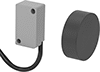
Tamper-Resistant Magnetic Contact Alarm Switches
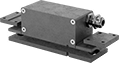
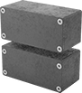
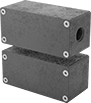
Prevent unauthorized use of doors or windows with a combination of coded magnets and contacts that wire to an alarm system. The coded magnets mean they can’t be bypassed with regular magnets. These switches actuate when the magnet comes within sensing distance of the switch and reset when the magnet moves away. Mount the magnet to your door or window and the switch to the frame. Connect the switch contacts to an alarm system, which will trigger when the magnet is pulled away as your door or window is opened.
Flush-mount switches are designed to mount against the door jam. They have a cord grip to reduce strain on your cord.
Surface-mount switches mount on the surface of your door. Those with a 1/2 conduit connection are ready to directly attach to your conduit.
| No. of Circuits Controlled | Switch Starting Position | Industry Designation | Switching Current @ Voltage | Max. Sensing Distance | No. of Terminals | Conduit Trade Size | Lg. | Wd. | Ht. | Features | Environmental Rating | Each | |
Painted Zinc Housing with Screw Terminals | |||||||||||||
|---|---|---|---|---|---|---|---|---|---|---|---|---|---|
Screw On—Flush Mount | |||||||||||||
| 2 | 1 Off (Normally Open) and 1 On (Normally Closed) | DPST-1NO/1NC | 0.2 A @ 30 V DC | 0.26" | 7 | __ | 4.33" | 1.38" | 1.26" | Auxiliary NO (Normally Open) Alarm, Nickel-Plated Brass Cord Grip | IP67 | 0000000 | 000000000 |
Screw On—Surface Mount | |||||||||||||
| 2 | 1 Off (Normally Open) and 1 On (Normally Closed) | DPST-1NO/1NC | 0.2 A @ 30 V DC | 0.26" | 7 | __ | 2.96" | 1.38" | 1.34" | Auxiliary NO (Normally Open) Alarm | IP67 | 0000000 | 00000000 |
| 2 | 1 Off (Normally Open) and 1 On (Normally Closed) | DPST-1NO/1NC | 0.2 A @ 30 V DC | 0.26" | 7 | 1/2 | 2.96" | 1.38" | 1.34" | Auxiliary NO (Normally Open) Alarm | IP67 | 0000000 | 00000000 |