


About Motor Switches and Starters
More
Choosing an Electrical Switch
More
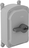
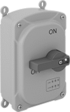
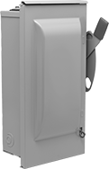
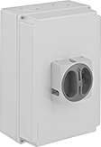
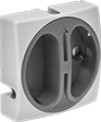
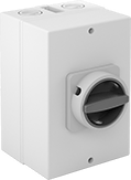
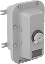
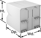
Washdown Enclosed Motor Switches
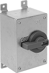
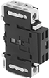
Steel Housing
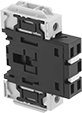
and Lockout
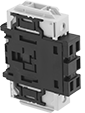
Housing, Lockout,
and Power Indicator
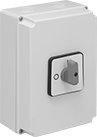
Install these switches in areas with oil, coolant, corrosive chemicals, and regular washdowns. They're rated IP69K and NEMA 4X and 12 or 12K. Since they’re already protected inside a housing, you can mount them to a wall if there’s no space left in your electrical panel. You need to grip and twist the lever to actuate, so they won’t accidentally turn on or off if something bumps into them. To lock them in the off position, attach a padlock (not included) to the lever. Use these switches to turn motors on and off, or with other circuits such as lighting and electric heat circuits. They do not provide overload protection.
Switches with a plastic housing can be turned into a handheld control for moving around your workstation by attaching a cord and cord grip. The housing is PBT polyester, so it won’t swell in moist environments.
Switches with a power indicator use LED lights to show the status of power flowing into the switch and power flowing from the switch to your motor. This can help you check for issues, such as a welded contact or phase loss, without having to open the housing.
Switching | ||||||||||||
|---|---|---|---|---|---|---|---|---|---|---|---|---|
| No. of Circuits Controlled | Electrical Phase (hp) | Switch Starting Position | Industry Designation | Current, A | Voltage | Ht. | Wd. | Wire Connection Type | Environmental Rating | Specifications Met | Each | |
Stays Switched (Maintained) | ||||||||||||
304 Stainless Steel Housing with Lockout | ||||||||||||
| 3 | Three (30 hp @ 240 V AC) | 3 Off (Normally Open) | 3PST-NO | 100 | 600V AC | 10.3" | 7.3" | Screw Terminals | NEMA 4X, IP69K, NEMA 12K | UL Listed, C-UL Listed, UL 746C, UL 94 5VA | 00000000 | 000000000 |
PBT Plastic Housing with Lockout | ||||||||||||
| 3 | Three (30 hp @ 240 V AC) | 3 Off (Normally Open) | 3PST-NO | 100 | 600V AC | 11" | 7.28" | Screw Terminals | NEMA 4X, IP69K, NEMA 12K | UL Listed, C-UL Listed, UL 746C, UL 94 5VA | 00000000 | 000000 |
PBT Plastic Housing with Lockout, Power Indicator | ||||||||||||
| 3 | Three (30 hp @ 240 V AC) | 3 Off (Normally Open) | 3PST-NO | 100 | 600V AC | 10.9" | 7.3" | Screw Terminals | NEMA 4X, IP69K, NEMA 12 | UL Listed, C-UL Listed, UL 746C, UL 94 5VA | 00000000 | 000000 |
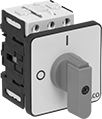
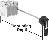
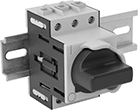
Durable Disconnect Switches
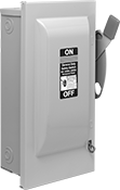
Protected by a steel enclosure, these switches withstand tougher conditions than switches in a plastic housing. Also known as safety switches, they have quick-make/quick-break action to eliminate arcing and prolong switch life. They have a lockout to secure in the off position using a padlock (not included).
Switches with safety interlock keep the door closed when the switch is on and prevent the switch from turning on when the door is open.
Switches with a fuse holder are used where overload protection is needed. When the current exceeds the fuse’s rating, the fuse will blow, interrupting the circuit to prevent the switch from overheating, breaking, or causing a fire. These switches require rejection-style fuse clips when used with UL Class RK1, RK5, or T fuses. Note: Horsepower ratings are based on time-delay fuses installed.
Switches with a viewing window let you see the switch position without opening the enclosure.
Switches | ||||||||||||||
|---|---|---|---|---|---|---|---|---|---|---|---|---|---|---|
Switching | Rejection-Style Fuse Clips for RK1 and RK5 Fuse Class | |||||||||||||
| Current, A | Voltage | Switch Action | Industry Designation | Electrical Phase (hp) | For No. of Wires | For Fuse Class | Ht. | Wd. | Environmental Rating | Specifications Met | Each | Each | ||
Enamel-Coated Steel with Black Actuator | ||||||||||||||
3 Circuits with Lockout, Safety Interlock | ||||||||||||||
| 100 | 600V AC/ 600V DC | Stays Switched (Maintained) | 3PDT | Single (20 hp @ 240 V AC) Single (40 hp @ 480 V AC) Single (40 hp @ 600 V AC) | 3 | __ | 29 15/16" | 12" | NEMA 1 | UL Listed | 000000 | 000000000 | 000000 | 00 |
3 Circuits with Lockout, Safety Interlock, Fuse Holder | ||||||||||||||
| 100 | 600V AC/ 600V DC | Stays Switched (Maintained) | 3PDT | Single (10 hp @ 480 V AC) Three (25 hp @ 480 V AC) Three (30 hp @ 600 V AC) | 3 | RK1, RK5, J, K5, H | 38 7/16" | 12" | NEMA 1 | UL Listed | 000000 | 00000000 | 000000 | 00 |
Enamel-Coated Steel with Black/Red Actuator | ||||||||||||||
3 Circuits with Lockout, Safety Interlock, Fuse Holder, Viewing Window | ||||||||||||||
| 100 | 600V AC/ 600V DC | Stays Switched (Maintained) | 3PST | Three (75 hp @ 600 V AC) | 4 | RK1, RK5, J, K5, H | 21 7/8" | 9" | NEMA 1 | UL Listed, CSA Certified | 0000000 | 000000 | 00000000 | 000000 |
Powder-Coated Steel with Red Actuator | ||||||||||||||
2 Circuits with Lockout, Safety Interlock, Fuse Holder | ||||||||||||||
| 100 | 240V AC/ 250V DC | Stays Switched (Maintained) | DPST | Single (15 hp @ 240 V AC) | 3 | RK1, RK5, K5, T, H | 23 1/8" | 11 3/4" | NEMA 1 | UL Listed | 0000000 | 000000 | 00000000 | 00000 |
3 Circuits with Lockout, Safety Interlock | ||||||||||||||
| 100 | 240V AC/ 250V DC | Stays Switched (Maintained) | 3PST | Single (15 hp @ 240 V AC) Three (30 hp @ 240 V AC) | 3 | __ | 23 1/8" | 11 3/4" | NEMA 1 | UL Listed | 0000000 | 000000 | 000000 | 00 |
3 Circuits with Lockout, Safety Interlock, Fuse Holder | ||||||||||||||
| 100 | 240V AC/ 250V DC | Stays Switched (Maintained) | 3PST | Single (15 hp @ 240 V AC) Three (30 hp @ 240 V AC) | 4 | RK1, RK5, K5, T, H | 23 1/8" | 11 3/4" | NEMA 1 | UL Listed | 0000000 | 000000 | 00000000 | 00000 |
| Rejection-Style Fuse Clip for T Fuse Class | 00000000 | Each | 000000 |
Outdoor Durable Disconnect Switches
A raintight NEMA 3R rated enclosure protects these switches from falling liquids and light splashing. The enclosure is steel, so it withstands tougher conditions than plastic enclosures. All have quick-make/quick-break action to eliminate arcing and prolong switch life. They have a lockout to secure in the off position using a padlock (not included).
Switches with safety interlock keep the door closed when the switch is on, and prevent the switch from turning on when the door is open.
Use switches with a fuse holder where overload protection is needed. When the current exceeds the rating of the fuse, it blows. This interrupts the circuit and prevents overheating, damage, and fire. When used with UL Class RK1, RK5, or T fuses, they require rejection-style fuse clips. Note: Horsepower ratings are based on time-delay fuses installed.
Switches with a viewing window let you see the switch position without opening the enclosure.
Switches | ||||||||||||
|---|---|---|---|---|---|---|---|---|---|---|---|---|
Switching | Rejection-Style Fuse Clips for RK1 and RK5 Fuse Class | |||||||||||
| Current, A | Voltage | Switch Action | Industry Designation | Electrical Phase (hp) | For No. of Wires | For Fuse Class | Ht. | Wd. | Each | Each | ||
Gray Enamel-Coated Steel with Black/Red Actuator | ||||||||||||
3 Circuits with Lockout, Safety Interlock, Fuse Holder, Viewing Window | ||||||||||||
| 100 | 600V AC/ 600V DC | Stays Switched (Maintained) | 3PST | Three (75 hp @ 600 V AC) | 4 | RK1, RK5, J, H | 22 1/8" | 9 1/16" | 0000000 | 000000000 | 00000000 | 000000 |
Gray Powder-Coated Steel with Red Actuator | ||||||||||||
2 Circuits with Lockout, Safety Interlock, Fuse Holder | ||||||||||||
| 100 | 240V AC/ 250V DC | Stays Switched (Maintained) | DPST | Single (15 hp @ 240 V AC) | 3 | RK1, RK5, K5, T, H | 23 1/8" | 12" | 0000000 | 000000 | 00000000 | 00000 |
3 Circuits with Lockout, Safety Interlock | ||||||||||||
| 100 | 240V AC/ 250V DC | Stays Switched (Maintained) | 3PST | Three (30 hp @ 240 V AC) | 3 | __ | 23 1/8" | 12" | 0000000 | 000000 | 000000 | 00 |
3 Circuits with Lockout, Safety Interlock, Fuse Holder | ||||||||||||
| 100 | 240V AC/ 250V DC | Stays Switched (Maintained) | 3PST | Single (15 hp @ 240 V AC) Three (30 hp @ 240 V AC) | 4 | RK1, RK5, K5, T, H | 23 1/8" | 11 3/4" | 0000000 | 000000 | 00000000 | 00000 |
| Rejection-Style Fuse Clip for T Fuse Class | 00000000 | Each | 000000 |
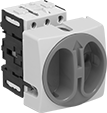
Panel-Mount Disconnect Switches
Install these switches in a panel cutout. They cut power and keep it isolated to prevent equipment from starting up during inspection and maintenance. All are UL listed, C-UL listed, and CE marked—they meet American, Canadian, and European safety standards.
Switches with lockout secure in the off position with a padlock with a maximum shackle diameter of 5/16” (not included).
Add auxiliary contact blocks to send a signal or connect to another device, such as an alarm or indicating light.
Use additional power poles to control more than three circuits. Add neutral poles to open and close the neutral leg of a three phase system.
Terminal covers prevent contact with live terminals.
Switching | |||||||||
|---|---|---|---|---|---|---|---|---|---|
| Current, A | Voltage | Industry Designation | Electrical Phase (hp) | Ht. | Wd. | Dp. Behind Panel | Environmental Rating | Each | |
Yellow Plastic Housing with Red Actuator | |||||||||
Stays Switched (Maintained) | |||||||||
3 Circuits—For 3/8" Panel Cutout Dia. | |||||||||
| 100 | 600V AC | 3PST | Single (10 hp @ 240 V AC) Single (5 hp @ 120 V AC) Three (25 hp @ 240 V AC) | 3 3/4" | 3 3/4" | 2 11/16" | IP40 | 00000000 | 0000000 |
3 Circuits with Lockout—For 3/8" Panel Cutout Dia. | |||||||||
| 100 | 600V AC | 3PST | Single (10 hp @ 240 V AC) Single (5 hp @ 120 V AC) Three (25 hp @ 240 V AC) | 3 3/8" | 3 3/8" | 2 11/16" | IP40 | 00000000 | 000000 |
Gray Plastic Housing with Gray Actuator | |||||||||
Stays Switched (Maintained) | |||||||||
3 Circuits—For 3/8" Panel Cutout Dia. | |||||||||
| 100 | 600V AC | 3PST | Single (10 hp @ 240 V AC) Single (5 hp @ 120 V AC) Three (25 hp @ 240 V AC) | 3 3/4" | 3 3/4" | 2 11/16" | IP40 | 00000000 | 000000 |
3 Circuits with Lockout—For 3/8" Panel Cutout Dia. | |||||||||
| 100 | 600V AC | 3PST | Single (10 hp @ 240 V AC) Single (5 hp @ 120 V AC) Three (25 hp @ 240 V AC) | 3 3/8" | 3 3/8" | 2 11/16" | IP40 | 00000000 | 000000 |
| "Main Switch" Label with Adhesive Back—13/16" Ht. × 3 3/16" Wd. | 0000000 | Each | 000000 |
| Switching Current, A | Each | |
| 10 | 0000000 | 000000 |
| Switching Current, A | Specifications Met | Each | |
| 100 | UL Listed, CE Marked | 00000000 | 000000 |
| Switching Current, A | Specifications Met | Each | |
| 100 | UL Listed, CE Marked | 00000000 | 000000 |
| For Current, A | Specifications Met | Each | |
| 80/100 | UL Listed, CE Marked | 00000000 | 000000 |

Enclosed Disconnect Switches
Cut power and keep it isolated to prevent equipment from starting up during inspection and maintenance. These switches are housed in a protective enclosure that resists denting, chipping, and cracking. Mount them to the wall when you run out of space in an electrical panel.
Switches with lockout secure in the off position with a padlock with a maximum shackle diameter of 5/16” (not included).
Add auxiliary contact blocks to send a signal or connect to another device, such as an alarm or indicating light.
Use additional power poles to control more than three circuits. Add neutral poles to open and close the neutral leg of a three phase system.
Switching | ||||||||
|---|---|---|---|---|---|---|---|---|
| Current, A | Voltage | Industry Designation | Electrical Phase (hp) | Ht. | Wd. | Environmental Rating | Each | |
Plastic Housing with Red Actuator | ||||||||
Stays Switched (Maintained) | ||||||||
3 Circuits | ||||||||
| 100 | 600V AC | 3PST | Single (5 hp @ 120 V AC) Single (10 hp @ 240 V AC) Three (25 hp @ 240 V AC) | 8 11/16" | 5 7/8" | IP40, NEMA 3 | 00000000 | 0000000 |
3 Circuits with Lockout | ||||||||
| 100 | 600V AC | 3PST | Single (5 hp @ 120 V AC) Single (10 hp @ 240 V AC) Three (25 hp @ 240 V AC) | 8 11/16" | 5 7/8" | IP40, NEMA 3 | 00000000 | 000000 |
Plastic Housing with Gray Actuator | ||||||||
Stays Switched (Maintained) | ||||||||
3 Circuits | ||||||||
| 100 | 600V AC | 3PST | Single (5 hp @ 120 V AC) Single (10 hp @ 240 V AC) Three (25 hp @ 240 V AC) | 8 11/16" | 5 7/8" | IP40, NEMA 3 | 00000000 | 000000 |
3 Circuits with Lockout | ||||||||
| 100 | 600V AC | 3PST | Single (5 hp @ 120 V AC) Single (10 hp @ 240 V AC) Three (25 hp @ 240 V AC) | 8 11/16" | 5 7/8" | IP40, NEMA 3 | 00000000 | 000000 |
| "Main Switch" Label with Adhesive Back—13/16" Ht. × 3 3/16" Wd. | 0000000 | Each | 000000 |
Plastic Housing with Red Actuator | |||||
|---|---|---|---|---|---|
| For Switching Current | Ht. | Wd. | Dp. | Each | |
| 80A, 100A | 3 3/8" | 3 3/8" | 1 5/16" | 0000000 | 000000 |
| Switching Current, A | Each | |
| 10 | 0000000 | 000000 |
| Switching Current, A | Specifications Met | Each | |
| 100 | UL Listed, CE Marked | 00000000 | 000000 |
| Switching Current, A | Specifications Met | Each | |
| 100 | UL Listed, CE Marked | 00000000 | 000000 |
| For Current, A | Specifications Met | Each | |
| 80/100 | UL Listed, CE Marked | 00000000 | 000000 |
Washdown Enclosed Disconnect Switches
The IP66 rated housing not only shields these switches from washdowns but also makes them durable enough to be mounted outside of an electrical panel. These switches cut power and keep it isolated to prevent equipment from starting up during inspection and maintenance.
Switches with lockout secure in the off position with a padlock with a maximum shackle diameter of 5/16” (not included).
Switching | ||||||||
|---|---|---|---|---|---|---|---|---|
| Current, A | Voltage | Switch Action | Industry Designation | Electrical Phase (hp) | Ht. | Wd. | Each | |
Plastic Housing with Red Actuator | ||||||||
3 Circuits with Lockout | ||||||||
| 100 | 600V AC | Stays Switched (Maintained) | 3PST | Single (5 hp @ 120 V AC) Single (10 hp @ 240 V AC) Three (25 hp @ 240 V AC) | 11" | 7 1/2" | 0000000 | 0000000 |
| "Main Switch" Label with Adhesive Back—13/16" Ht. × 3 3/16" Wd. | 0000000 | Each | 000000 |
Hazardous Location Enclosed Disconnect Switches
With a housing that’s designed to contain an explosion, these switches are safe to use in areas where ignitable concentrations of flammable or combustible gas, dust, or fibers may be present. They meet NEC Class I Div. 1 and 2, Groups B, C, D, and Class II, Div. 1 and 2, Groups E, F, and G. Use them to cut power and keep it isolated, so equipment won’t accidentally start up during inspection or maintenance.
Made from aluminum, these switches also resist corrosion in wet or oily areas. They have a lockout, so you can secure them in the off position with a padlock (not included).
Switching | ||||||||||
|---|---|---|---|---|---|---|---|---|---|---|
| Current, A | Voltage | Switch Action | Industry Designation | Electrical Phase (hp) | Ht. | Wd. | Environmental Rating | Each | ||
Powder-Coated Aluminum Housing with Yellow Actuator | ||||||||||
3 Circuits with Lockout | ||||||||||
| B | 100 | 600V AC | Stays Switched (Maintained) | 3PST | Three (50 hp @ 600 V AC) | 13 1/16" | 8 1/8" | NEC Class I Divisions 1, 2 Groups B, C, D NEC Class II Divisions 1, 2 Groups E, F, G NEC Zone 1 Groups IIB, IIA NEMA 4X NEMA 7 NEMA 9 | 0000000 | 000000000 |
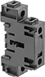
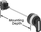
Enclosure Disconnect Switches
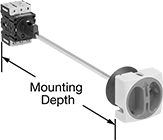
Install these switches inside an enclosure to prevent it from opening when power is on—turn the switch to disconnect power and release the door. Cut the shaft to fit the enclosure. Use a padlock (not included) to lock switches in the off position. Mount to DIN rail inside an enclosure; mounting depth is the distance from the panel door to the DIN rail. All meet at least one safety standard.
Switches with a fuse holder are used where overload protection is needed. When the current exceeds the fuse's rating, the fuse will blow, interrupting the circuit to prevent the switch from overheating, breaking, or causing a fire.
Add auxiliary contact blocks to send a signal or connect to another device, such as an alarm or indicating light.
Use optional sealing gaskets in washdown environments; they create an IP65 rated seal around the actuator.
Use additional power poles to control more than three circuits. Add neutral poles to open and close the neutral leg of a three-phase system.
Add junction blocks to connect a ground wire.
Terminal covers prevent contact with live terminals.
Switches | |||||||||||||
|---|---|---|---|---|---|---|---|---|---|---|---|---|---|
Switching | Replacement Shafts | Replacement Shaft Bases | |||||||||||
| Current, A | Voltage | Electrical Phase (hp) | Ht. | Wd. | For DIN Rail Ht., mm | Mounting Dp. | Environmental Rating | Each | Each | Each | |||
Gray Plastic Housing with Gray Actuator | |||||||||||||
3 Circuits—For 1 3/16" Panel Cutout Dia. | |||||||||||||
| 100 | 600V AC | Single (5 hp @ 120 V AC) Single (10 hp @ 240 V AC) Three (10 hp @ 120 V AC) Three (25 hp @ 240 V AC) | 3 3/8" | 3 3/8" | 35 | 5 11/16"-16 1/2" | IP40 | 0000000 | 0000000 | 0000000 | 000000 | 0000000 | 00000 |
Yellow Plastic Housing with Red Actuator | |||||||||||||
3 Circuits—For 1 3/16" Panel Cutout Dia. | |||||||||||||
| 100 | 600V AC | Single (5 hp @ 120 V AC) Single (10 hp @ 240 V AC) Three (10 hp @ 120 V AC) Three (25 hp @ 240 V AC) | 3 3/8" | 3 3/8" | 35 | 5 11/16"-16 1/2" | IP40 | 0000000 | 000000 | 0000000 | 00000 | 0000000 | 0000 |
4 Circuits—For 1 3/16" Panel Cutout Dia. | |||||||||||||
| 100 | 600V AC | Single (5 hp @ 120 V AC) Single (10 hp @ 240 V AC) Three (10 hp @ 120 V AC) Three (25 hp @ 240 V AC) | 3 3/8" | 3 3/8" | 35 | 5 11/16"-16 1/2" | IP40 | 0000000 | 000000 | 0000000 | 00000 | 0000000 | 0000 |
Switches | |||||||||||||||
|---|---|---|---|---|---|---|---|---|---|---|---|---|---|---|---|
Switching | Replacement Shafts | Replacement Shaft Bases | |||||||||||||
| Current, A | Voltage | Electrical Phase (hp) | For No. of Fuses | For Fuse Class | Ht. | Wd. | For DIN Rail Ht., mm | Mounting Dp. | Environmental Rating | Each | Each | Each | |||
Gray Plastic Housing with Black Actuator | |||||||||||||||
3 Circuits—For 1 15/32" Panel Cutout Dia. | |||||||||||||||
| 100 | 600V AC | Single (Not Rated) Three (30 hp @ 240 V AC) Three (75 hp @ 600 V AC) | 3 | J | 7 5/16" | 5 15/16" | 35 | 7 7/8"-20 9/16" | IP20 | 00000000 | 0000000 | 00000000 | 000000 | 00000000 | 000000 |
Yellow Plastic Housing with Red Actuator | |||||||||||||||
3 Circuits—For 1 15/32" Panel Cutout Dia. | |||||||||||||||
| 100 | 600V AC | Single (Not Rated) Three (30 hp @ 240 V AC) Three (75 hp @ 600 V AC) | 3 | J | 7 5/16" | 5 15/16" | 35 | 7 7/8"-20 9/16" | IP20 | 00000000 | 000000 | 00000000 | 00000 | 00000000 | 00000 |

| No. of Circuits Controlled | Switching Current @ Voltage | Switch Starting Position | Industry Designation | Each | |
| 1 | 10 A @ 600 V AC | 1 Off (Normally Open) or 1 On (Normally Closed) | SPDT | 0000000 | 000000 |

| For Switching Current, A | Each | |
| 80A, 100A | 0000000 | 00000 |
| Switching Current, A | Specifications Met | Each | |
| 100 | UL Listed, CE Marked | 00000000 | 000000 |
| Switching Current, A | Specifications Met | Each | |
| 100 | UL Listed, CE Marked | 00000000 | 000000 |
| For Current, A | Specifications Met | Each | |
| 80/100 | UL Listed, CE Marked | 00000000 | 000000 |
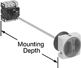
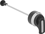
Manual Override Enclosure Disconnect Switches
Keep power running while you access your enclosure. Unlike standard enclosure disconnect switches, which shut off power as you open your enclosure, these have an override function. Engaging the override allows you to take voltage reading, troubleshoot an error code, or fine tune the speed of your line. When the override is off, these work like a standard disconnect switch—a safety interlock prevents your enclosure from opening when power is on. The interlock also prevents the switch from turning on when the door is already open. Cut the shaft to fit your enclosure. All have a lockout so you can secure them in the off position with a padlock (not included).
Add auxiliary contact blocks to send a signal or connect to another device, such as an alarm or indicating light.
Use additional power poles to control more than three circuits. Add neutral poles to open and close the neutral leg of a three-phase system.
Add junction blocks to connect a ground wire.
Terminal covers prevent contact with live terminals.
Switching | |||||||||
|---|---|---|---|---|---|---|---|---|---|
| Current, A | Voltage | Electrical Phase (hp) | Ht. | Wd. | For DIN Rail Ht., mm | Mounting Dp. | Environmental Rating | Each | |
Black Plastic Housing with Black Actuator | |||||||||
3 Circuits with Lockout, Safety Interlock—For 1 1/2" Panel Cutout Dia. | |||||||||
| 100 | 600V AC | Single (5 hp @ 120 V AC) Single (10 hp @ 240 V AC) Three (10 hp @ 120 V AC) Three (25 hp @ 240 V AC) | 3" | 4 1/16" | 35 | 5 11/16"-16 1/2" | IP66, NEMA 4X, NEMA 12 | 0000000 | 0000000 |
Black Plastic Housing with Red Actuator | |||||||||
3 Circuits with Lockout, Safety Interlock—For 1 1/2" Panel Cutout Dia. | |||||||||
| 100 | 600V AC | Single (5 hp @ 120 V AC) Single (10 hp @ 240 V AC) Three (10 hp @ 120 V AC) Three (25 hp @ 240 V AC) | 3" | 4 1/16" | 35 | 5 11/16"-16 1/2" | IP66, NEMA 4X, NEMA 12 | 0000000 | 000000 |
Switching | ||||||
|---|---|---|---|---|---|---|
| No. of Circuits Controlled | Current, A | Voltage | Switch Starting Position | Industry Designation | Each | |
| 1 | 10 | 600V AC | 1 Off (Normally Open) or 1 On (Normally Closed) | SPDT | 0000000 | 000000 |
| Switching Current, A | Specifications Met | Each | |
| 100 | UL Listed, CE Marked | 00000000 | 000000 |
| Switching Current, A | Specifications Met | Each | |
| 100 | UL Listed, CE Marked | 00000000 | 000000 |
| For Current, A | Specifications Met | Each | |
| 80/100 | UL Listed, CE Marked | 00000000 | 000000 |
DIN-Rail Mount Disconnect Switches
Often used in electrical enclosures, these switches mount directly to DIN rails. They cut power and keep it isolated to stop equipment from starting up during inspection and maintenance. For an extra level of security, add a padlock (not included) to lock out the actuator lever in the Off position.
Add auxiliary contact blocks to send a signal or connect to another device, such as an alarm or indicating light.
Use additional power poles to control additional circuits. Add neutral poles to open and close the neutral leg of a three-phase system.
Add junction blocks to connect a ground wire.
Terminal covers prevent contact with live terminals.
Switching | ||||||||||||
|---|---|---|---|---|---|---|---|---|---|---|---|---|
| Current, A | Voltage | Switch Action | Industry Designation | Electrical Phase (hp) | Ht. | Wd. | For Max. Padlock Shackle Dia. | For DIN Rail Ht., mm | Wire Connection Type | Specifications Met | Each | |
Gray Plastic Housing with Black Actuator | ||||||||||||
3 Circuits with Lockout | ||||||||||||
| 100 | 600V AC | Stays Switched (Maintained) | 3PST | Single (5 hp @ 120 V AC) Single (10 hp @ 240 V AC) Three (25 hp @ 240 V AC) | 3 3/4" | 2 7/8" | 5/16" | 35 | Screw Terminals | UL Listed, C-UL Listed, CE Marked, UL 508 | 0000000 | 0000000 |
4 Circuits with Lockout | ||||||||||||
| 100 | 600V AC | Stays Switched (Maintained) | 4PST | Single (5 hp @ 120 V AC) Single (10 hp @ 240 V AC) Three (25 hp @ 240 V AC) | 3 3/4" | 2 7/8" | 5/16" | 35 | Screw Terminals | UL Listed, C-UL Listed, CE Marked, UL 508 | 0000000 | 000000 |
| Switching Current, A | Each | |
| 10 | 0000000 | 000000 |
| Switching Current, A | Specifications Met | Each | |
| 100 | UL Listed, CE Marked | 00000000 | 000000 |
| Switching Current, A | Specifications Met | Each | |
| 100 | UL Listed, CE Marked | 00000000 | 000000 |
| For Current, A | Specifications Met | Each | |
| 80/100 | UL Listed, CE Marked | 00000000 | 000000 |
Circuit Board Relays
Smaller than relays with electrical wiring, these relays fit in compact devices. Mount them through holes on circuit boards with their solder pin terminals. Use them to control heaters, fans, and other high-power components from a low-power circuit.
| Number of Terminals | Input Voltage | Control Current, mA | Switching Current @ Voltage | Max. Switching Voltage | Mechanical Life Cycles | Ht. | Wd. | Dp. | Pin Lg. | Each | |
Mechanical | |||||||||||
|---|---|---|---|---|---|---|---|---|---|---|---|
2 Circuits Controlled with 2 Off (Normally Open)—DPST-NO | |||||||||||
| 14 | 12V DC | 240 | 100 A @ 400 V AC | 400V AC | 1,000,000 | 2.1" | 2.1" | 2.3" | 0.18" | 0000000 | 000000 |
| 14 | 24V DC | 120 | 100 A @ 400 V AC | 400V AC | 1,000,000 | 2.1" | 2.1" | 2.3" | 0.18" | 0000000 | 00000 |
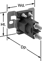
Stud-Terminal Relays
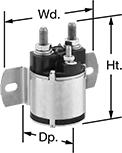
These relays are suitable for DC-powered equipment such as forklifts, floor scrubbers, and trucks. They are rated for continuous operation for cycles that run longer than 30 seconds.
3-terminal relays require the same input and switching voltage. 4- and 6-terminal relays allow different input and switching voltages.
| Number of Terminals | Input Voltage | Control Power, VA | Full Load Switching Current @ Voltage | Ht. | Wd. | Dp. | Stud Thread Size | Each | |
1 Circuit Controlled with 1 Off (Normally Open)—SPST-NO | |||||||||
|---|---|---|---|---|---|---|---|---|---|
| 3 | 12V DC | 12 | 100 A @ 12 V DC | 3.6" | 3.1" | 2.2" | 5/16"-24 | 0000000 | 000000 |
| 4 | 12V DC | 12 | 100 A @ 12 V DC | 3.6" | 3.1" | 2.2" | 5/16"-24 | 0000000 | 00000 |
| 4 | 24V DC | 12 | 100 A @ 24 V DC | 3.6" | 3.1" | 2.2" | 5/16"-24 | 0000000 | 00000 |
| 4 | 36V DC | 12 | 100 A @ 36 V DC | 3.6" | 3.1" | 2.2" | 5/16"-24 | 0000000 | 00000 |
1 Circuit Controlled with 1 Off (Normally Open) or 1 On (Normally Closed)—SPDT | |||||||||
| 6 | 12V DC | 12 | 100 A @ 12 V DC | 4.7" | 3.1" | 2.2" | 5/16"-24 | 0000000 | 00000 |
| 6 | 24V DC | 12 | 100 A @ 24 V DC | 4.7" | 3.1" | 2.2" | 5/16"-24 | 0000000 | 000000 |
| 6 | 36V DC | 12 | 100 A @ 36 V DC | 4.7" | 3.1" | 2.2" | 5/16"-24 | 0000000 | 00000 |
Water-Resistant Stud-Terminal Relays
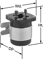
Sealed to keep out water, these relays are often used for DC-powered equipment such as forklifts, floor scrubbers, and trucks. They are rated for continuous operation for cycles that run longer than 30 seconds.
| Number of Terminals | Input Voltage | Control Power, VA | Full Load Switching Current @ Voltage | Ht. | Wd. | Dp. | Stud Thread Size | Each | |
1 Circuit Controlled with 1 Off (Normally Open)—SPST-NO | |||||||||
|---|---|---|---|---|---|---|---|---|---|
| 4 | 12V DC | 8.1 | 100 A @ 12 V DC | 2.9" | 3.3" | 2.1" | 5/16"-24 | 0000000 | 000000 |
| 4 | 24V DC | 8.1 | 100 A @ 24 V DC | 2.9" | 3.3" | 2.1" | 5/16"-24 | 0000000 | 00000 |
| 4 | 36V DC | 8.1 | 100 A @ 36 V DC | 2.9" | 3.3" | 2.1" | 5/16"-24 | 0000000 | 00000 |
1 Circuit Controlled with 1 Off (Normally Open) or 1 On (Normally Closed)—SPDT | |||||||||
| 6 | 12V DC | 12 | 100 A @ 12 V DC | 4.6" | 3.3" | 2.9" | 5/16"-24 | 0000000 | 000000 |
| 6 | 24V DC | 12 | 100 A @ 24 V DC | 4.6" | 3.3" | 2.9" | 5/16"-24 | 0000000 | 000000 |