


Actuator Style Actuator Style |
|---|
 | Toggle |
Wire Connection Type Wire Connection Type |
|---|
 | |
| Quick- Disconnect Terminals | Screw Terminals |
Switch Action Switch Action |
|---|
|
System of Measurement System of Measurement |
|---|
|
Switching Current Switching Current | Show |
|---|
|
Switching Current Switching Current | Hide |
|---|
Environmental Rating Environmental Rating |
|---|
Mounting Location Mounting Location |
|---|
|
Specifications Met Specifications Met |
|---|
Switch Type Switch Type |
|---|
|
Illumination Illumination |
|---|
|
Switch Starting Position Switch Starting Position |
|---|
RoHS (Restriction of Hazardous Substances) RoHS (Restriction ofHazardous Substances) |
|---|
|
REACH (Registration, Evaluation, Authorization and Restriction of Chemicals) REACH (Registration,Evaluation, Authorization and Restriction of Chemicals) |
|---|
|
Choosing an Electrical Switch
More
Wet-Location Toggle Switches


A rubber seal protects these switches from splashing water.
NEMA 4, 13, and IP68 rated switches are protected against oil/coolant spraying, washdowns, and temporary submersion.
Switches with an on-on or on-(on) position designation alternate power between sets of terminals.
![]() For technical drawings and 3-D models, click on a part number.
For technical drawings and 3-D models, click on a part number.
| No. of Circuits Controlled | Switch Starting Position | Switch Action | No. of Terminals | Industry Designation | Position Designation | Color | Switching Current @ Voltage | Max. Voltage | Mounting Hardware Included | Choose a Wire Connection Type | Each | |
2 Position with Rounded Toggle—NEMA 4, NEMA 13, IP68 | ||||||||||||
|---|---|---|---|---|---|---|---|---|---|---|---|---|
For 1/2" Panel Cutout Dia. | ||||||||||||
| 1 | 1 Off (Normally Open) | Stays Switched (Maintained) | 2 | SPST-NO | On-Off | __ | 15 A @ 125 V AC, 12 A @ 28 V DC | 28V DC 277V AC | Yes | 0000000 | 000000 | |
| 1 | 1 Off (Normally Open) or 1 On (Normally Closed) | Stays Switched (Maintained) | 3 | SPDT | On-On | __ | 15 A @ 125 V AC, 12 A @ 28 V DC | 28V DC 277V AC | Yes | 0000000 | 00000 | |
| 4 | 4 Off (Normally Open) or 4 On (Normally Closed) | Stays Switched (Maintained) | 12 | 4PDT | On-On | __ | 15 A @ 125 V AC, 12 A @ 28 V DC | 28V DC 277V AC | Yes | Quick-Disconnect Terminals | 00000000 | 00000 |
2 Position with Flat Toggle—NEMA 4, NEMA 13, IP68 | ||||||||||||
For 1/2" Panel Cutout Dia. | ||||||||||||
| 1 | 1 Off (Normally Open) | Stays Switched (Maintained) | 2 | SPST-NO | On-Off | Yellow | 15 A @ 125 V AC, 12 A @ 28 V DC | 28V DC 277V AC | Yes | Quick-Disconnect Terminals | 0000000 | 00000 |
3 Position with Rounded Toggle—NEMA 4, NEMA 13, IP68 | ||||||||||||
For 1/2" Panel Cutout Dia. | ||||||||||||
| 1 | 1 Off (Normally Open) or 1 On (Normally Closed) | Stays Switched (Maintained) | 3 | SPDT | On-Off-On | __ | 15 A @ 125 V AC, 12 A @ 28 V DC | 28V DC 277V AC | Yes | 0000000 | 00000 | |
Mil. Spec. Washdown Toggle Switches

These switches meet MIL-S-3950. A rubber seal protects them from washdowns.
Switches with an on-on, on-on-on, or (on)-on-on position designation alternate power between sets of terminals.
![]() For technical drawings and 3-D models, click on a part number.
For technical drawings and 3-D models, click on a part number.
| No. of Circuits Controlled | Switch Starting Position | Switch Action | No. of Terminals | Industry Designation | Position Designation | Switching Current @ Voltage | Max. Voltage | Dp. Behind Panel | Mounting Hardware Included | Wire Connection Type | Each | |
2 Position | ||||||||||||
|---|---|---|---|---|---|---|---|---|---|---|---|---|
For 1/2" Panel Cutout Dia. | ||||||||||||
| 4 | 4 Off (Normally Open) | Stays Switched (Maintained) | 8 | 4PST | On-Off | 15 A @ 125 V AC, 12 A @ 28 V DC | 28V DC 125V AC | 1.35" | Yes | Screw Terminals | 00000000 | 000000 |
| 4 | 4 Off (Normally Open) or 4 On (Normally Closed) | Stays Switched (Maintained) | 12 | 4PDT | On-On | 15 A @ 125 V AC, 12 A @ 28 V DC | 28V DC 125V AC | 1.35" | Yes | Screw Terminals | 00000000 | 00000 |
3 Position | ||||||||||||
For 1/2" Panel Cutout Dia. | ||||||||||||
| 4 | 4 Off (Normally Open) or 4 On (Normally Closed) | Stays Switched (Maintained) | 12 | 4PDT | On-Off-On | 15 A @ 125 V AC, 12 A @ 28 V DC | 28V DC 125V AC | 1.35" | Yes | Screw Terminals | 00000000 | 00000 |
Pull-to-Unlock Toggle Switches

Prevent accidental actuation—these toggle switches must be pulled out before they can switch a circuit.
Ball end toggle switches are rated NEMA 4, 13, and IP68 for protection against washdowns, oil/coolant spraying, and temporary submersion.
Switches with an on-on position designation alternate power between sets of terminals.
![]() For technical drawings and 3-D models, click on a part number.
For technical drawings and 3-D models, click on a part number.
| No. of Circuits Controlled | Switch Starting Position | Switch Action | No. of Terminals | Industry Designation | Position Designation | Switching Current @ Voltage | Max. Voltage | Mounting Hardware Included | Mounting Thread Size | Wire Connection Type | Environmental Rating | Each | |
2 Position | |||||||||||||
|---|---|---|---|---|---|---|---|---|---|---|---|---|---|
For 1/2" Panel Cutout Dia. | |||||||||||||
| 1 | 1 Off (Normally Open) or 1 On (Normally Closed) | Stays Switched (Maintained) | 3 | SPDT | On-On | 15 A @ 125 V AC, 12 A @ 28 V DC | 28V DC 277V AC | Yes | 15/32"-32 | Screw Terminals | NEMA 4, NEMA 13, IP68 | 0000000 | 000000 |
3 Position | |||||||||||||
For 1/2" Panel Cutout Dia. | |||||||||||||
| 1 | 1 Off (Normally Open) or 1 On (Normally Closed) | Stays Switched (Maintained) | 3 | SPDT | On-Off-On | 15 A @ 125 V AC, 12 A @ 28 V DC | 28V DC 277V AC | Yes | 15/32"-32 | Screw Terminals | NEMA 4, NEMA 13, IP68 | 0000000 | 00000 |
Panel-Mount Compact Disconnect Switches
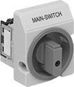
Install these switches in a panel cutout. Small enough to fit in tight spaces, they handle comparable electrical loads to standard sized switches. They cut power and keep it isolated to prevent equipment from starting up during inspection and maintenance. All have a lockout so you can secure them in the off position with a padlock (not included). They’re rated IP65 for protection from washdowns.
![]() For technical drawings and 3-D models, click on a part number.
For technical drawings and 3-D models, click on a part number.
Yellow Plastic Housing with Red Actuator | ||||||||
|---|---|---|---|---|---|---|---|---|
| Switching Current @ Voltage | Industry Designation | Electrical Phase (hp) | Ht. | Wd. | Dp. Behind Panel | Specifications Met | Each | |
Stays Switched (Maintained) | ||||||||
3 Circuits with Lockout—For 3/8" Panel Cutout Dia. | ||||||||
| 12 A @ 600 V AC, 16 A @ 24 V DC | 3PST | Single (1/2 hp @ 120 V AC) Three (1 hp @ 120 V AC) Three (3 hp @ 240 V AC) | 3 1/4" | 2 1/2" | 1 13/16" | UL Recognized Component, CSA Certified, UL 508 | 00000000 | 000000 |
4 Circuits with Lockout—For 3/8" Panel Cutout Dia. | ||||||||
| 12 A @ 600 V AC, 16 A @ 24 V DC | 4PST | Single (1/2 hp @ 120 V AC) Three (1 hp @ 120 V AC) Three (3 hp @ 240 V AC) | 3 1/4" | 2 1/2" | 1 13/16" | UL Recognized Component, CSA Certified | 00000000 | 00000 |
Enclosed Compact Disconnect Switches
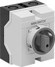
These small disconnect switches are sized to fit in tight spaces but can handle comparable electrical loads to standard sized switches. They cut power and keep it isolated to prevent equipment from starting up during inspection and maintenance. All have a lockout so you can secure them in the off position with a padlock (not included). They’re rated IP65 for protection from washdowns.
![]() For technical drawings and 3-D models, click on a part number.
For technical drawings and 3-D models, click on a part number.
Yellow Plastic Housing with Red Actuator | ||||||||
|---|---|---|---|---|---|---|---|---|
| Switching Current @ Voltage | Industry Designation | Electrical Phase (hp) | Ht. | Wd. | Environmental Rating | Specifications Met | Each | |
Stays Switched (Maintained) | ||||||||
3 Circuits with Lockout | ||||||||
| 12 A @ 600 V AC, 16 A @ 24 V DC | 3PST | Single (1/2 hp @ 120 V AC) Three (1 hp @ 120 V AC) Three (3 hp @ 240 V AC) | 4 3/4" | 3 13/16" | IP65 | UL Recognized Component, CSA Certified, UL 508 | 00000000 | 0000000 |
4 Circuits with Lockout | ||||||||
| 12 A @ 600 V AC, 16 A @ 24 V DC | 4PST | Single (1/2 hp @ 120 V AC) Three (1 hp @ 120 V AC) Three (3 hp @ 240 V AC) | 4 3/4" | 3 13/16" | IP65 | UL Recognized Component, CSA Certified | 00000000 | 000000 |
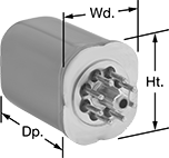
Compact Spade-Terminal Relays
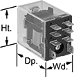
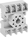
Smaller than standard spade-terminal relays in height and depth, these relays save space inside your control cabinet. Attach quick-disconnect terminals or plug relays into relay sockets.
Relay sockets (sold separately) mount to 35 mm DIN rail or flat surfaces.
![]() For technical drawings and 3-D models, click on a part number.
For technical drawings and 3-D models, click on a part number.
Relays | |||||||||||||||
|---|---|---|---|---|---|---|---|---|---|---|---|---|---|---|---|
Switching Current | Relay Sockets | ||||||||||||||
| Number of Terminals | Input Voltage | Control Current, mA | @ 120V AC | @28V DC | Max. Switching Voltage | Ht. | Wd. | Dp. | Quick-Disconnect Tab Wd. | Features | Specifications Met | Each | Each | ||
2 Circuits Controlled with 2 Off (Normally Open) or 2 On (Normally Closed)—DPDT | |||||||||||||||
| 8 | 24V AC | 50 | 15A | 12A | 300V AC | 1.1" | 0.9" | 1.6" | 0.187" | LED Indicating Light, Lockable Test Button, Mechanical Flag Indicator | UL Recognized Component, C-UL Recognized Component, CSA Certified, CE Marked | 00000000 | 000000 | 0000000 | 00000 |
| 8 | 120V AC | 10 | 15A | 12A | 300V AC | 1.1" | 0.9" | 1.6" | 0.187" | LED Indicating Light, Lockable Test Button, Mechanical Flag Indicator | UL Recognized Component, C-UL Recognized Component, CSA Certified, CE Marked | 00000000 | 00000 | 0000000 | 0000 |
| 8 | 240V AC | 5 | 15A | 12A | 300V AC | 1.1" | 0.9" | 1.6" | 0.187" | LED Indicating Light, Lockable Test Button, Mechanical Flag Indicator | UL Recognized Component, C-UL Recognized Component, CSA Certified, CE Marked | 00000000 | 00000 | 0000000 | 0000 |
| 8 | 12V DC | 75 | 15A | 12A | 300V AC | 1.1" | 0.9" | 1.6" | 0.187" | LED Indicating Light, Lockable Test Button, Mechanical Flag Indicator | UL Recognized Component, C-UL Recognized Component, CSA Certified, CE Marked | 00000000 | 00000 | 0000000 | 0000 |
| 8 | 24V DC | 38 | 15A | 12A | 300V AC | 1.1" | 0.9" | 1.6" | 0.187" | LED Indicating Light, Lockable Test Button, Mechanical Flag Indicator | UL Recognized Component, C-UL Recognized Component, CSA Certified, CE Marked | 00000000 | 00000 | 0000000 | 0000 |
3 Circuits Controlled with 3 Off (Normally Open) or 3 On (Normally Closed)—3PDT | |||||||||||||||
| 11 | 24V AC | 63 | 15A | 12A | 300V AC | 1.1" | 1.2" | 1.6" | 0.187" | LED Indicating Light, Lockable Test Button, Mechanical Flag Indicator | UL Recognized Component, C-UL Recognized Component, CSA Certified, CE Marked | 00000000 | 00000 | 0000000 | 00000 |
| 11 | 120V AC | 13 | 15A | 12A | 300V AC | 1.1" | 1.2" | 1.6" | 0.187" | LED Indicating Light, Lockable Test Button, Mechanical Flag Indicator | UL Recognized Component, C-UL Recognized Component, CSA Certified, CE Marked | 00000000 | 00000 | 0000000 | 00000 |
| 11 | 240V AC | 6 | 15A | 12A | 300V AC | 1.1" | 1.2" | 1.6" | 0.187" | LED Indicating Light, Lockable Test Button, Mechanical Flag Indicator | UL Recognized Component, C-UL Recognized Component, CSA Certified, CE Marked | 00000000 | 00000 | 0000000 | 00000 |
| 11 | 12V DC | 117 | 15A | 12A | 300V AC | 1.1" | 1.2" | 1.6" | 0.187" | LED Indicating Light, Lockable Test Button, Mechanical Flag Indicator | UL Recognized Component, C-UL Recognized Component, CSA Certified, CE Marked | 00000000 | 00000 | 0000000 | 00000 |
| 11 | 24V DC | 58 | 15A | 12A | 300V AC | 1.1" | 1.2" | 1.6" | 0.187" | LED Indicating Light, Lockable Test Button, Mechanical Flag Indicator | UL Recognized Component, C-UL Recognized Component, CSA Certified, CE Marked | 00000000 | 00000 | 0000000 | 00000 |
4 Circuits Controlled with 4 Off (Normally Open) or 4 On (Normally Closed)—4PDT | |||||||||||||||
| 14 | 24V AC | 63 | 15A | 12A | 300V AC | 1.1" | 1.6" | 1.6" | 0.187" | LED Indicating Light, Lockable Test Button, Mechanical Flag Indicator | UL Recognized Component, C-UL Recognized Component, CSA Certified, CE Marked | 00000000 | 00000 | 0000000 | 00000 |
| 14 | 120V AC | 13 | 15A | 12A | 300V AC | 1.1" | 1.6" | 1.6" | 0.187" | LED Indicating Light, Lockable Test Button, Mechanical Flag Indicator | UL Recognized Component, C-UL Recognized Component, CSA Certified, CE Marked | 00000000 | 00000 | 0000000 | 00000 |
| 14 | 240V AC | 6 | 15A | 12A | 300V AC | 1.1" | 1.6" | 1.6" | 0.187" | LED Indicating Light, Lockable Test Button, Mechanical Flag Indicator | UL Recognized Component, C-UL Recognized Component, CSA Certified, CE Marked | 00000000 | 00000 | 0000000 | 00000 |
| 14 | 12V DC | 125 | 15A | 12A | 300V AC | 1.1" | 1.6" | 1.6" | 0.187" | LED Indicating Light, Lockable Test Button, Mechanical Flag Indicator | UL Recognized Component, C-UL Recognized Component, CSA Certified, CE Marked | 00000000 | 00000 | 0000000 | 00000 |
| 14 | 24V DC | 6 | 15A | 12A | 300V AC | 1.1" | 1.6" | 1.6" | 0.187" | LED Indicating Light, Lockable Test Button, Mechanical Flag Indicator | UL Recognized Component, C-UL Recognized Component, CSA Certified, CE Marked | 00000000 | 00000 | 0000000 | 00000 |
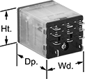
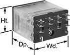
Hazardous Location Circular-Pin Relays
These sealed relays meet UL Class I, Division 2, Groups A, B, C, and D for use in hazardous locations. The circular pin terminals plug into relay sockets for easy installation.
Relay sockets (sold separately) mount to 35 mm DIN rail or flat surfaces.
Relays | Relay Sockets | ||||||||||||
|---|---|---|---|---|---|---|---|---|---|---|---|---|---|
| Number of Terminals | Input Voltage | Control Current, mA | Switching Current @ 120V AC/24V DC | Max. Switching Voltage | hp @ Switching Voltage | Ht. | Wd. | Dp. | Environmental Rating | Each | Each | ||
2 Circuits Controlled with 2 Off (Normally Open) or 2 On (Normally Closed)—DPDT | |||||||||||||
| 8 | 120V AC | 10 | 12A | 300V AC | 1/3 hp @ 120 V AC | 1.6" | 1.4" | 2.1" | NEC Class I Division 2 Groups A, B, C, D | 0000000 | 0000000 | 0000000 | 00000 |
| 8 | 24V DC | 38 | 12A | 300V AC | 1/3 hp @ 120 V AC | 1.6" | 1.4" | 2.1" | NEC Class I Division 2 Groups A, B, C, D | 0000000 | 000000 | 0000000 | 0000 |