


Switching Voltage Switching Voltage | Show |
|---|
|
Switching Voltage Switching Voltage | Hide |
|---|
Input Voltage Input Voltage |
|---|
|
Relay Type Relay Type |
|---|
| Signal | |
Operation Type Operation Type |
|---|
|
Switch Starting Position Switch Starting Position |
|---|
Application Application |
|---|
|
Switch Action Switch Action |
|---|
|
Wire Connection Type Wire Connection Type |
|---|
 | |
| Quick- Disconnect Terminals | Screw Terminals |
Number of Pedals Number of Pedals |
|---|
|
System of Measurement System of Measurement |
|---|
|
Actuator Style Actuator Style |
|---|
| Foot Pedal | |
DFARS (Defense Acquisition Regulations Supplement) DFARS (Defense AcquisitionRegulations Supplement) |
|---|
Electrical Connection Type Electrical Connection Type |
|---|
| Hardwire | |
RoHS (Restriction of Hazardous Substances) RoHS (Restriction ofHazardous Substances) |
|---|
|
REACH (Registration, Evaluation, Authorization and Restriction of Chemicals) REACH (Registration,Evaluation, Authorization and Restriction of Chemicals) |
|---|
|
Choosing an Electrical Switch
More
Foot Switches
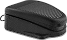
Press these switches with your foot for convenient, hands-free operation.
Switches with front pivot reduce user fatigue.
Foot Switches | |||||||||||||
|---|---|---|---|---|---|---|---|---|---|---|---|---|---|
Mounting | Optional Guards | ||||||||||||
| No. of Circuits Controlled | Switch Starting Position | Switch Action | Industry Designation | Switching Current @ Voltage | Wire Connection Type | No. of Terminals | Fasteners Included | No. of Holes | Hole Dia. | Each | Each | ||
1 Speed | |||||||||||||
Iron Housing with 1 Pedal | |||||||||||||
| 2 | 2 Off (Normally Open) or 2 On (Normally Closed) | Springs Back (Momentary) | DPDT | 15 A @ 125 V AC, 10 A @ 250 V AC, 3 A; 3 V DC | Quick-Disconnect Terminals | 6 | No | 2 | 0.22" | 000000 | 000000 | 000000 | 000000 |
Ultra-Thin Signal Relays
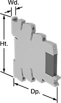
Maximize space inside your control cabinet—these relays are extra narrow. Also known as output modules, use them with circuits that control electrical signals. They have no moving parts, which provides an extended service life. Mount to 35 mm DIN rail.
![]() For technical drawings and 3-D models, click on a part number.
For technical drawings and 3-D models, click on a part number.
| Number of Terminals | Input Voltage | Switching Current @ Voltage | Ht. | Wd. | Dp. | Features | Specifications Met | Each | |
1 Circuit Controlled with 1 Off (Normally Open)—SPST-NO | |||||||||
|---|---|---|---|---|---|---|---|---|---|
| 5 | 24V AC/24V DC-230V AC/230V DC | 3.5 A @ 3/33 V DC | 3.528" | 0.504" | 3.457" | Power Indicator | CE Marked, UL Listed, C-UL Listed | 0000000 | 000000 |
| 5 | 19.2V DC-28.8V DC | 3 A @ 3/33 V DC | 3.15" | 0.244" | 3.646" | Power Indicator | UL Recognized Component, C-UL Listed, UL-Listed, C-UL Recognized Component | 0000000 | 00000 |
Signal-Conditioning Ultra-Thin Signal Relays
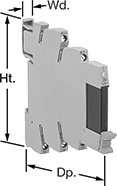
Also known as input modules, these relays condition electrical signals into signals for PLCs and microprocessors and prevent power surges from reaching these devices. They are extra narrow to maximize space inside your control cabinet. Mount to 35 mm DIN rail.
| Switching Voltage | Number of Terminals | Input Voltage | Control Current, mA | Switching Current @ 28V DC | Output Voltage | Ht. | Wd. | Dp. | Specifications Met | Each | |
1 Circuit Controlled with 1 Off (Normally Open)—SPST-NO | |||||||||||
|---|---|---|---|---|---|---|---|---|---|---|---|
| 3V DC/48V DC | 5 | 19.2-28.8V DC | 100 | 100mA | 3-48V DC | 3.15" | 0.244" | 3.701" | UL Recognized Component | 0000000 | 000000 |
Signal Relays
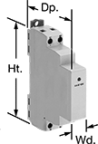
Use these relays with circuits that control electrical signals. They have no moving parts, which provides an extended service life. Mount to 35 mm DIN rail.
| Number of Terminals | Input Voltage | Switching Current @ Voltage | Ht. | Wd. | Dp. | Features | Specifications Met | Each | |
1 Circuit Controlled with 1 Off (Normally Open)—SPST-NO | |||||||||
|---|---|---|---|---|---|---|---|---|---|
| 4 | 3.5-32V DC | 15 A @ 3/50 V DC | 3.5" | 0.7" | 2.6" | Power Indicator | UL Listed C-UL Listed CSA Certified CE Marked | 0000000 | 0000000 |