


Clear All
Actuator Style Actuator Style |
|---|
 | Push Button |
Push-Button Style Push-Button Style |
|---|
 | Mushroom |
Switching Voltage Switching Voltage | Show |
|---|
|
Switching Voltage Switching Voltage | Hide |
|---|
Illumination Illumination |
|---|
|
Environmental Rating Environmental Rating |
|---|
Number of Buttons Number of Buttons |
|---|
|
System of Measurement System of Measurement |
|---|
|
Push-Button Shape Push-Button Shape |
|---|
|
Light Pattern Light Pattern |
|---|
|
Light Technology Light Technology |
|---|
|
REACH (Registration, Evaluation, Authorization and Restriction of Chemicals) REACH (Registration,Evaluation, Authorization and Restriction of Chemicals) |
|---|
|
RoHS (Restriction of Hazardous Substances) RoHS (Restriction ofHazardous Substances) |
|---|
|
Industry Designation Industry Designation |
|---|
Bulb Voltage Bulb Voltage |
|---|
|
Number of Circuits Controlled per Button Number of CircuitsControlled per Button |
|---|
|
Actuator Material Actuator Material |
|---|
|
Auxiliary Contact Switch Starting Position Auxiliary ContactSwitch Starting Position |
|---|
|
Contact Type Contact Type |
|---|
|
Choosing an Electrical Switch
More
High-Visibility Plastic Emergency Stop Enclosed Push-Button Switches
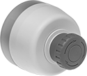
Panel Mount
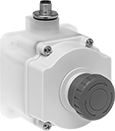
Surface Mount
8-Pole Micro M12
A red light flashes when the actuator is pushed, making it easy to see from a distance. These switches immediately cut power with a single push. They're housed in a protective yellow enclosure for quick identification. All have positive force contacts that will open a circuit when actuated even if a spring fails or the contacts stick. They're rated IP65 for protection from water projected by a nozzle.
Note: If wiring the switch and the bulb to the same circuit, the circuit voltage must not exceed bulb voltage.
Auxiliary contacts allow you to add a signaling device or control another switch.
![]() For technical drawings and 3-D models, click on a part number.
For technical drawings and 3-D models, click on a part number.
Auxiliary Contacts | ||||||||||||||
|---|---|---|---|---|---|---|---|---|---|---|---|---|---|---|
| No. of Buttons | Actuator Color | No. of Circuits Controlled per Button | Switch Starting Position | Switch Action | Industry Designation | Switching Current @ Voltage | Max. Voltage | No. of | Switch Starting Position | Switch Position | Light Pattern | Bulb Voltage | Each | |
With 8-Pole Micro M12 Plug | ||||||||||||||
Panel Mount with Turn Reset and Emergency Stop Label | ||||||||||||||
| 1 | Red | 2 | 2 On (Normally Closed) | Stays Switched (Maintained) | DPST-NC | 2 A @ 60 V AC, 1 A @ 30 V DC | 60V AC 75V DC | 1 | 1 Off (Normally Open) | On (Normally Closed),Off (Normally Open) | Continuous Green, Flashing Red | 30V DC | 000000 | 0000000 |
| 1 | Red | 2 | 2 On (Normally Closed) | Stays Switched (Maintained) | DPST-NC | 2 A @ 60 V AC, 1 A @ 30 V DC | 60V AC 75V DC | 1 | 1 Off (Normally Open) | On (Normally Closed),Off (Normally Open) | Continuous Yellow, Flashing Red | 30V DC | 000000 | 000000 |
| 1 | Red | 2 | 2 On (Normally Closed) | Stays Switched (Maintained) | DPST-NC | 2 A @ 60 V AC, 1 A @ 30 V DC | 60V AC 75V DC | 1 | 1 Off (Normally Open) | On (Normally Closed),Off (Normally Open) | Flashing Red | 30V DC | 000000 | 000000 |
Surface Mount with Turn Reset and Emergency Stop Label | ||||||||||||||
| 1 | Red | 2 | 2 On (Normally Closed) | Stays Switched (Maintained) | DPST-NC | 2 A @ 60 V AC, 1 A @ 30 V DC | 60V AC 75V DC | 1 | 1 Off (Normally Open) | On (Normally Closed),Off (Normally Open) | Continuous Green, Flashing Red | 30V DC | 000000 | 000000 |
| 1 | Red | 2 | 2 On (Normally Closed) | Stays Switched (Maintained) | DPST-NC | 2 A @ 60 V AC, 1 A @ 30 V DC | 60V AC 75V DC | 1 | 1 Off (Normally Open) | On (Normally Closed),Off (Normally Open) | Continuous Yellow, Flashing Red | 30V DC | 000000 | 000000 |
| 1 | Red | 2 | 2 On (Normally Closed) | Stays Switched (Maintained) | DPST-NC | 2 A @ 60 V AC, 1 A @ 30 V DC | 60V AC 75V DC | 1 | 1 Off (Normally Open) | On (Normally Closed),Off (Normally Open) | Flashing Red | 30V DC | 000000 | 000000 |