Actuator Style Actuator Style |
---|
![]() | Push Button |
Switch Starting Position Switch Starting Position |
---|
Push-Button Style Push-Button Style |
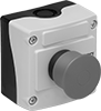
---|
![]() | Mushroom |
With Guard With Guard |
---|
|
Actuator Color Actuator Color |
---|
![]() | Red |
Switch Action Switch Action |
---|
|
System of Measurement System of Measurement |
---|
|
Wire Connection Type Wire Connection Type | Show |
---|
|
Wire Connection Type Wire Connection Type | Hide |
---|
Industry Designation Industry Designation |
---|
|
|
Push-Button Shape Push-Button Shape |
---|
|
Illumination Illumination |
---|
|
RoHS (Restriction of Hazardous Substances) RoHS (Restriction ofHazardous Substances) |
---|
|
REACH (Registration, Evaluation, Authorization and Restriction of Chemicals) REACH (Registration,Evaluation, Authorization and Restriction of Chemicals) |
---|
|
Choosing an Electrical Switch
More
About Relays
More
About Timer Relays
More
About Motor Switches and Starters
More
Plastic Emergency Stop Enclosed Push-Button Switches
Rated NEMA 3S, NEMA 4X, NEMA 13, and IP66, these plastic switches resist corrosion better than aluminum switches and withstand washdowns and oil/coolant spraying. Housed in a yellow enclosure for quick identification, they immediately cut power with a single push. They meet EN 418 for compliance with European machine directives for emergency stop applications. All have positive force contacts that will open a circuit when actuated even if a spring fails or the contacts stick.
Key reset switches are keyed alike, so if you buy multiple switches they will all reset with the same key.
Switches with a power indicator alert you from the front and sides when the switch has been actuated.
Switches with a guard prevent accidental actuation. For extra security, lock the button in the off position with a padlock (not included) to stop these switches from being reset or turned on during machine repairs.
For technical drawings and 3-D models, click on a part number.


Mounting | |||||||||||||||
---|---|---|---|---|---|---|---|---|---|---|---|---|---|---|---|
No. of Buttons | Actuator Color | No. of Circuits Controlled per Button | Switch Starting Position | Switch Action | No. of Terminals per Button | Industry Designation | Switching Current @ Voltage | Max. Voltage | Dia. | Conduit Trade Size | Fasteners Included | No. of Holes | Hole Dia. | Each | |
With Screw-Clamp Terminals | |||||||||||||||
Pull Reset | |||||||||||||||
1 | Red | 1 | 1 On (Normally Closed) | Stays Switched (Maintained) | 2 | SPST-NC | 6 A @ 120 V AC, 2.5 A @ 24 V DC | 600V AC 600V DC | 1 9/16" | 1/2 | No | 2 | 3/16" | 0000000 | 000000 |
1 | Red | 2 | 1 Off (Normally Open) and 1 On (Normally Closed) | Stays Switched (Maintained) | 4 | DPST-1NO/1NC | 6 A @ 120 V AC, 2.5 A @ 24 V DC | 600V AC 600V DC | 1 9/16" | 1/2 | No | 2 | 3/16" | 0000000 | 00000 |
1 | Red | 2 | 2 On (Normally Closed) | Stays Switched (Maintained) | 4 | DPST-NC | 6 A @ 120 V AC, 2.5 A @ 24 V DC | 600V AC 600V DC | 1 9/16" | 1/2 | No | 2 | 3/16" | 0000000 | 00000 |
Pull Reset with Guard | |||||||||||||||
1 | Red | 1 | 1 On (Normally Closed) | Stays Switched (Maintained) | 2 | SPST-NC | 6 A @ 120 V AC, 2.5 A @ 24 V DC | 600V AC 600V DC | 1 9/16" | 1/2 | No | 2 | 3/16" | 0000000 | 00000 |
1 | Red | 2 | 1 Off (Normally Open) and 1 On (Normally Closed) | Stays Switched (Maintained) | 4 | DPST-1NO/1NC | 6 A @ 120 V AC, 2.5 A @ 24 V DC | 600V AC 600V DC | 1 9/16" | 1/2 | No | 2 | 3/16" | 0000000 | 00000 |
1 | Red | 2 | 2 On (Normally Closed) | Stays Switched (Maintained) | 4 | DPST-NC | 6 A @ 120 V AC, 2.5 A @ 24 V DC | 600V AC 600V DC | 1 9/16" | 1/2 | No | 2 | 3/16" | 0000000 | 00000 |
Pull Reset with Power Indicator | |||||||||||||||
1 | Red | 1 | 1 On (Normally Closed) | Stays Switched (Maintained) | 2 | SPST-NC | 6 A @ 120 V AC, 2.5 A @ 24 V DC | 600V AC 600V DC | 2 1/8" | 1/2 | No | 2 | 3/16" | 0000000 | 00000 |
1 | Red | 2 | 1 Off (Normally Open) and 1 On (Normally Closed) | Stays Switched (Maintained) | 4 | DPST-1NO/1NC | 6 A @ 120 V AC, 2.5 A @ 24 V DC | 600V AC 600V DC | 2 1/8" | 1/2 | No | 2 | 3/16" | 0000000 | 00000 |
1 | Red | 2 | 2 On (Normally Closed) | Stays Switched (Maintained) | 4 | DPST-NC | 6 A @ 120 V AC, 2.5 A @ 24 V DC | 600V AC 600V DC | 2 1/8" | 1/2 | No | 2 | 3/16" | 0000000 | 00000 |
Key Reset (including 2 Keys) | |||||||||||||||
1 | Red | 1 | 1 On (Normally Closed) | Stays Switched (Maintained) | 2 | SPST-NC | 6 A @ 120 V AC, 2.5 A @ 24 V DC | 600V AC 600V DC | 1 9/16" | 1/2 | No | 2 | 3/16" | 0000000 | 00000 |
1 | Red | 2 | 1 Off (Normally Open) and 1 On (Normally Closed) | Stays Switched (Maintained) | 4 | DPST-1NO/1NC | 6 A @ 120 V AC, 2.5 A @ 24 V DC | 600V AC 600V DC | 1 9/16" | 1/2 | No | 2 | 3/16" | 0000000 | 00000 |
1 | Red | 2 | 2 On (Normally Closed) | Stays Switched (Maintained) | 4 | DPST-NC | 6 A @ 120 V AC, 2.5 A @ 24 V DC | 600V AC 600V DC | 1 9/16" | 1/2 | No | 2 | 3/16" | 0000000 | 00000 |
Turn Reset | |||||||||||||||
1 | Red | 1 | 1 On (Normally Closed) | Stays Switched (Maintained) | 2 | SPST-NC | 6 A @ 120 V AC, 2.5 A @ 24 V DC | 600V AC 600V DC | 1 9/16" | 1/2 | No | 2 | 3/16" | 0000000 | 00000 |
1 | Red | 2 | 1 Off (Normally Open) and 1 On (Normally Closed) | Stays Switched (Maintained) | 4 | DPST-1NO/1NC | 6 A @ 120 V AC, 2.5 A @ 24 V DC | 600V AC 600V DC | 1 9/16" | 1/2 | No | 2 | 3/16" | 0000000 | 00000 |
1 | Red | 2 | 2 On (Normally Closed) | Stays Switched (Maintained) | 4 | DPST-NC | 6 A @ 120 V AC, 2.5 A @ 24 V DC | 600V AC 600V DC | 1 9/16" | 1/2 | No | 2 | 3/16" | 0000000 | 00000 |
No. of Circuits Controlled | Switch Starting Position | No. of Terminals | Industry Designation | Each | |
1 | 1 On (Normally Closed) | 2 | SPST-NC | 0000000 | 000000 |
Manual Motor Starters
These starters are more compact than electrically actuated motor starters. Use them when multiple motor circuits are housed in one panel. They provide on/off control for a motor and protect it from overloads—starters will shut the motor off if current exceeds the full-load current rating. Set the adjustable overload relay for the exact overload current needed.
Note: The full-load current rating of your motor must fall within the starter’s overload current range. Look for the full-load current rating on the motor’s faceplate, or estimate the current rating (given the motor’s horsepower and voltage).
Add auxiliary contact blocks to send a signal or connect to another device, such as an alarm or indicating light.

Motor Starters | |||||||||||
---|---|---|---|---|---|---|---|---|---|---|---|
Switching | Auxiliary Contact Blocks | ||||||||||
Overload Current, A | Current, A | Voltage | Electrical Phase (hp) | No. of Poles | Ht. | Wd. | Wire Connection Type | Each | Each | ||
1-1.6 | 25 | 600V AC | Single (1/10 hp @ 120 V AC) Three (3/4 hp @ 480 V AC) | 3 | 3.5" | 2.1" | Screw-Clamp Terminals | 0000000 | 0000000 | 0000000 | 000000 |
1.6-2.5 | 25 | 600V AC | Single (1/6 hp @ 240 V AC) Three (1/2 hp @ 240 V AC) Three (1 hp @ 480 V AC) | 3 | 3.5" | 2.1" | Screw-Clamp Terminals | 0000000 | 000000 | 0000000 | 00000 |
2.5-4 | 25 | 600V AC | Single (1/8 hp @ 120 V AC) Single (1/3 hp @ 240 V AC) Three (1 hp @ 240 V AC) Three (2 hp @ 480 V AC) | 3 | 3.5" | 2.1" | Screw-Clamp Terminals | 0000000 | 000000 | 0000000 | 00000 |
4-6.3 | 25 | 600V AC | Single (1/4 hp @ 120 V AC) Single (1/2 hp @ 240 V AC) Three (1 1/2 hp @ 240 V AC) Three (3 hp @ 480 V AC) | 3 | 3.5" | 2.1" | Screw-Clamp Terminals | 0000000 | 000000 | 0000000 | 00000 |
6.3-9 | 25 | 600V AC | Single (1/3 hp @ 120 V AC) Single (1 hp @ 240 V AC) Three (2 1/2 hp @ 240 V AC) Three (5 hp @ 480 V AC) | 3 | 3.5" | 2.1" | Screw-Clamp Terminals | 0000000 | 000000 | 0000000 | 00000 |
9-12.5 | 25 | 600V AC | Single (1/2 hp @ 120 V AC) Single (2 hp @ 240 V AC) Three (3 hp @ 240 V AC) Three (7 1/2 hp @ 480 V AC) | 3 | 3.5" | 2.1" | Screw-Clamp Terminals | 0000000 | 000000 | 0000000 | 00000 |
12.5-16 | 25 | 600V AC | Single (1 hp @ 120 V AC) Single (2 1/2 hp @ 240 V AC) Three (5 hp @ 240 V AC) Three (10 hp @ 480 V AC) | 3 | 3.5" | 2.1" | Screw-Clamp Terminals | 0000000 | 000000 | 0000000 | 00000 |
16-20 | 25 | 600V AC | Single (1 1/2 hp @ 120 V AC) Single (3 hp @ 240 V AC) Three (5 hp @ 240 V AC) Three (10 hp @ 480 V AC) | 3 | 3.5" | 2.1" | Screw-Clamp Terminals | 0000000 | 000000 | 0000000 | 00000 |
20-25 | 25 | 600V AC | Single (2 hp @ 120 V AC) Single (3 hp @ 240 V AC) Three (7 1/2 hp @ 240 V AC) Three (15 hp @ 480 V AC) | 3 | 3.5" | 2.1" | Screw-Clamp Terminals | 0000000 | 000000 | 0000000 | 00000 |
PG-16 to 1/2" NPT Thread Adapter | 0000000 | Each | 000000 |

Conduit | |||||||||
---|---|---|---|---|---|---|---|---|---|
Ht. | Wd. | Dp. | Housing Material | Number of Connections | Thread Size | Environment | Environmental Rating | Each | |
Enclosure with On/Off Lever | |||||||||
5.9" | 3.7" | 5.2" | Plastic | 4 | PG-16 | Wet Location | IP64 | 0000000 | 000000 |
DIN-Rail Mount Long-Life High-Current Relays

With no moving parts, these solid state relays have an extended service life. Mount them directly to 35 mm DIN rail. They have an integrated heat sink that disperses heat to provide optimal convection cooling. An LED indicator tells you if they are open or closed. Relays are rated for continuous operating duty. They do not switch DC loads.
For technical drawings and 3-D models, click on a part number.
Number of Terminals | Input Voltage | Control Current, mA | Full Load Switching Current @ 600V AC | hp @ Switching Voltage | Ht. | Wd. | Dp. | Specifications Met | Each | |
1 Circuit Controlled with 1 Off (Normally Open)—SPST-NO | ||||||||||
---|---|---|---|---|---|---|---|---|---|---|
Single Phase | ||||||||||
4 | 5-32V DC | 11 | 85A | 2 hp @ 115 V AC 5 hp @ 230 V AC | 5.1" | 2.8" | 6.6" | UL Listed C-UL Listed CE Marked | 0000000 | 0000000 |
4 | 20-275V AC/24-190V DC | 13 | 85A | 2 hp @ 115 V AC 5 hp @ 230 V AC | 5.1" | 2.8" | 6.6" | UL Listed C-UL Listed CE Marked | 0000000 | 000000 |
2 Circuits Controlled with 2 Off (Normally Open)—DPST-NO | ||||||||||
Two Phase | ||||||||||
6 | 5-32V DC | 10 | 40A | 5 hp @ 230 V AC 10 hp @ 480 V AC | 4.3" | 2.8" | 5" | UL Listed C-UL Listed CE Marked | 0000000 | 000000 |
6 | 5-32V DC | 10 | 75A | 10 hp @ 230 V AC 20 hp @ 480 V AC | 5.6" | 2.8" | 5.6" | UL Listed C-UL Listed CE Marked | 0000000 | 000000 |
6 | 20-275V AC/24-190V DC | 2 | 40A | 5 hp @ 230 V AC 10 hp @ 480 V AC | 4.3" | 2.8" | 5" | UL Listed C-UL Listed CE Marked | 0000000 | 000000 |
6 | 20-275V AC/24-190V DC | 2 | 75A | 10 hp @ 230 V AC 20 hp @ 480 V AC | 5.6" | 2.8" | 5.6" | UL Listed C-UL Listed CE Marked | 0000000 | 000000 |
3 Circuits Controlled with 3 Off (Normally Open)—3PST-NO | ||||||||||
Three Phase | ||||||||||
8 | 5-32V DC | 10 | 30A | 5 hp @ 230 V AC 10 hp @ 480 V AC | 4.3" | 2.8" | 5" | UL Listed C-UL Listed CE Marked | 0000000 | 000000 |
8 | 20-275V AC/24-190V DC | 2 | 30A | 5 hp @ 230 V AC 10 hp @ 480 V AC | 4.3" | 2.8" | 5" | UL Listed C-UL Listed CE Marked | 0000000 | 000000 |
10 | 5-32V DC | 10 | 40A | 5 hp @ 230 V AC 10 hp @ 480 V AC | 5.3" | 2.1" | 4.7" | UL Listed C-UL Listed CE Marked | 0000000 | 000000 |
10 | 5-32V DC | 10 | 65A | 10 hp @ 230 V AC 20 hp @ 480 V AC | 5.6" | 2.8" | 5.6" | UL Listed C-UL Listed CE Marked | 0000000 | 000000 |
10 | 20-275V AC/24-190V DC | 1 | 65A | 10 hp @ 230 V AC 20 hp @ 480 V AC | 5.6" | 2.8" | 5.6" | UL Listed C-UL Listed CE Marked | 0000000 | 000000 |
10 | 20-275V AC/24-190V DC | 2 | 40A | 5 hp @ 230 V AC 10 hp @ 480 V AC | 5.3" | 2.1" | 4.7" | UL Listed C-UL Listed CE Marked | 0000000 | 000000 |
DIN-Rail Mount Timer Relays

Mount these relays directly to 35 mm DIN rail. After selecting a timing range, use the knob to adjust the trip time within the timing range. With no moving parts, these solid state relays have an extended service life.
Timing Range | |||||||||||
---|---|---|---|---|---|---|---|---|---|---|---|
Number of Terminals | Input Voltage | Control Current, mA | No. of | Overall | Switching Current @ 250V AC | Ht. | Wd. | Dp. | Specifications Met | Each | |
Delayed Start (Delay-on-Make) | |||||||||||
1 Circuit Controlled with 1 Off (Normally Open)—SPST-NO | |||||||||||
6 | 24-240V AC/24-240V DC | 7 | 7 | 0.1 sec.-100 hrs. | 0.7A | 3.5" | 0.7" | 2.7" | UL Listed C-UL Listed CSA Certified CE Marked | 0000000 | 000000 |
Interval | |||||||||||
1 Circuit Controlled with 1 Off (Normally Open)—SPST-NO | |||||||||||
6 | 24-240V AC | 7 | 7 | 0.1 sec.-100 hrs. | 0.7A | 3.5" | 0.7" | 2.7" | UL Listed C-UL Listed CSA Certified CE Marked | 0000000 | 00000 |
Enclosure Humidistats


Reduce the humidity in your enclosure to prevent condensation that can cause corrosion and short circuits. These humidistats switch your heater on when the enclosure reaches the relative humidity setting. Once the humidity falls by 5%, the heater switches off. To install, clip humidistats to a DIN rail.
Nonadjustable humidistats work for most applications. They keep humidity below 65%, which is when condensation is most likely to form. Since they aren’t adjustable, the humidity setting can’t be tampered with or accidentally changed. For critical components, use adjustable humidistats to set the relative humidity you need in your enclosure. Use a lower humidity setting in damp environments and places with frequent temperature changes. Condensation is more likely in these situations.
CSA Certified, CSA-US Certified, CE Marked, and VDE Certified, these humidistats meet American, Canadian, and European safety standards. They also meet UL 94 V-0, so if they catch fire, they self-extinguish within 10 seconds and won’t spread the fire by dripping.
Relative Humidity | Overall | |||||||||||
---|---|---|---|---|---|---|---|---|---|---|---|---|
Setting | Difference | Tolerance | Voltage | Current, A | For DIN Rail Height, mm | Height | Width | Depth | Environmental Rating | Specifications Met | Each | |
Nonadjustable | ||||||||||||
65% | 5% | ±1% | 120V AC | 16 | 35 | 2 1/2" | 1 5/8" | 1 1/2" | IP20 | CE Marked; VDE Certified; CSA Certified; CSA-US Certified; UL 94 V-0 | 0000000 | 000000 |
65% | 5% | ±1% | 240V AC | 16 | 35 | 2 1/2" | 1 5/8" | 1 1/2" | IP20 | CE Marked; VDE Certified; CSA Certified; CSA-US Certified; UL 94 V-0 | 0000000 | 00000 |
Adjustable | ||||||||||||
40% to 90% | 5% | ±1% | 120V AC | 16 | 35 | 2 1/2" | 1 5/8" | 1 1/2" | IP20 | CE Marked; VDE Certified; CSA Certified; CSA-US Certified; UL 94 V-0 | 0000000 | 00000 |
40% to 90% | 5% | ±1% | 240V AC | 16 | 35 | 2 1/2" | 1 5/8" | 1 1/2" | IP20 | CE Marked; VDE Certified; CSA Certified; CSA-US Certified; UL 94 V-0 | 0000000 | 00000 |
DIN-Rail Mount AC Equipment Circuit Breakers
These circuit breakers meet UL 1077 requirements for supplemental circuit protection and are designed for use downstream of a branch circuit breaker. Use them with small transformers, lighting, and control circuits. All are thermal/magnetic—breakers trip when heat is generated by sustained, low-level overload current, but will trip quickly when the magnetic field in the coil senses a high-current short circuit. Mount directly to DIN rail.
Breakthrough current is the maximum current that the circuit breaker can safely stop in the event of a short circuit.
Alarm (sold separately) sends an audible signal when the breaker is tripped.
For technical drawings and 3-D models, click on a part number.


Voltage | Frequency, Hz | Breakthrough Current | For DIN Rail Size, mm | Wire Connection Type | Ht. | Wd. | Dp. | Temp. Range, °F | Features | Specifications Met | Choose a Current, A | Each | |
1 Pole—Toggle Style | |||||||||||||
---|---|---|---|---|---|---|---|---|---|---|---|---|---|
277V AC | 50/60 | 5,000 A @ 277 V AC | 35 | Screw-Clamp Terminals | 3.15" | 0.7" | 2.36" | -40° to 165° | Time Delay Trip | UL 1077, CSA Certified, CE Marked | 000000 | 000000 | |
2 Pole—Toggle Style | |||||||||||||
277V AC/480YV AC | 50/60 | 5,000 A @ 277 V AC 5,000 A @ 480 V AC | 35 | Screw-Clamp Terminals | 3.15" | 1.4" | 2.36" | -40° to 165° | Time Delay Trip | UL 1077, CSA Certified, CE Marked | 000000 | 00000 | |
3 Pole—Toggle Style | |||||||||||||
277V AC/480YV AC | 50/60 | 5,000 A @ 277 V AC 5,000 A @ 480 V AC | 35 | Screw-Clamp Terminals | 3.15" | 2.1" | 2.36" | -40° to 165° | Time Delay Trip | UL 1077, CSA Certified, CE Marked | 000000 | 00000 |
Current | Includes | Each | |
0.5 A @ 110 V DC, 2 A @ 250 V AC | Two Sets of Auxillary Contacts | 0000000 | 000000 |
High-Inrush DIN-Rail Mount AC Equipment Circuit Breakers
Able to handle high inrush currents caused by equipment startup, these circuit breakers are suitable for motor and larger transformer applications. They meet UL 1077 requirements for supplemental circuit protection and are designed for use downstream of a branch circuit breaker. All are thermal/magnetic—breakers trip when heat is generated by sustained, low-level overload current, but will trip quickly when the magnetic field in the coil senses a high-current short circuit. Mount directly to DIN rail.
Breakthrough current is the maximum current that the circuit breaker can safely stop in the event of a short circuit.
Alarm (sold separately) sends an audible signal when the breaker is tripped.
For technical drawings and 3-D models, click on a part number.


Voltage | Frequency, Hz | Breakthrough Current | For DIN Rail Size, mm | Wire Connection Type | Ht. | Wd. | Dp. | Temp. Range, °F | Features | Specifications Met | Choose a Current, A | Each | |
1 Pole—Toggle Style | |||||||||||||
---|---|---|---|---|---|---|---|---|---|---|---|---|---|
277V AC | 50/60 | 5,000 A @ 277 V AC | 35 | Screw-Clamp Terminals | 3.15" | 0.7" | 2.36" | 25° to 100° | Time Delay Trip | UL 1077, CSA Certified, CE Marked, IEC European Standards | 000000 | 000000 | |
2 Pole—Toggle Style | |||||||||||||
277V AC/480YV AC | 50/60 | 5,000 A @ 277 V AC 5,000 A @ 480 V AC | 35 | Screw-Clamp Terminals | 3.15" | 1.4" | 2.36" | 25° to 100° | Time Delay Trip | UL 1077, CSA Certified, CE Marked, IEC European Standards | 000000 | 00000 | |
3 Pole—Toggle Style | |||||||||||||
277V AC/480YV AC | 50/60 | 5,000 A @ 277 V AC 5,000 A @ 480 V AC | 35 | Screw-Clamp Terminals | 3.15" | 2.1" | 2.36" | 25° to 100° | Time Delay Trip | UL 1077, CSA Certified, CE Marked, IEC European Standards | 000000 | 00000 |
Current | Includes | Each | |
0.5 A @ 110 V DC, 2 A @ 250 V AC | Two Sets of Auxillary Contacts | 0000000 | 000000 |
DIN-Rail Mount AC Branch Circuit Breakers


Use these circuit breakers upstream from small transformers, lighting, and control circuits. They meet UL 489 requirements for branch circuit protection. All are thermal/magnetic—breakers trip when heat is generated by sustained, low-level overload current, but will trip quickly when the magnetic field in the coil senses a high-current short circuit. Mount directly to DIN rail.
Breakthrough current is the maximum current that the circuit breaker can safely stop in the event of a short circuit.
Alarm (sold separately) sends an audible signal when the breaker is tripped.
For technical drawings and 3-D models, click on a part number.
Voltage | Frequency, Hz | Breakthrough Current | For DIN Rail Size, mm | Wire Connection Type | Ht. | Wd. | Dp. | Temp. Range, °F | Features | Specifications Met | Choose a Current, A | Each | |
1 Pole—Toggle Style | |||||||||||||
---|---|---|---|---|---|---|---|---|---|---|---|---|---|
277V AC | 50/60 | 10,000 A @ 277 V AC | 35 | Screw-Clamp Terminals | 4.13" | 0.7" | 2.36" | -4° to 140° | Time Delay Trip | UL 489, CSA Certified | 000000 | 000000 | |
2 Pole—Toggle Style | |||||||||||||
277V AC/480YV AC | 50/60 | 10,000 A @ 277 V AC 10,000 A @ 480 V AC | 35 | Screw-Clamp Terminals | 4.13" | 1.39" | 2.36" | -4° to 140° | Time Delay Trip | UL 489, CSA Certified | 000000 | 00000 | |
3 Pole—Toggle Style | |||||||||||||
277V AC/480YV AC | 50/60 | 10,000 A @ 277 V AC 10,000 A @ 480 V AC | 35 | Screw-Clamp Terminals | 4.13" | 2.09" | 2.36" | -4° to 140° | Time Delay Trip | UL 489, CSA Certified | 000000 | 000000 |

Current | Includes | Each | |
0.5 A @ 110 V DC, 2 A @ 250 V AC | Two Sets of Auxillary Contacts | 0000000 | 000000 |
High-Inrush DIN-Rail Mount AC Branch Circuit Breakers
Able to handle high inrush current caused by equipment startup, use these circuit breakers upstream from motors and larger transformer applications. They meet UL 489 requirements for branch circuit protection. All are thermal/magnetic—breakers trip when heat is generated by sustained, low-level overload current, but will trip quickly when the magnetic field in the coil senses a high-current short circuit. Mount directly to DIN rail.
Breakthrough current is the maximum current that the circuit breaker can safely stop in the event of a short circuit.
Alarm (sold separately) sends an audible signal when the breaker is tripped.
For technical drawings and 3-D models, click on a part number.


Voltage | Frequency, Hz | Breakthrough Current | For DIN Rail Size, mm | Wire Connection Type | Ht. | Wd. | Dp. | Temp. Range, °F | Features | Specifications Met | Choose a Current, A | Each | |
1 Pole—Toggle Style | |||||||||||||
---|---|---|---|---|---|---|---|---|---|---|---|---|---|
277V AC | 50/60 | 10,000 A @ 277 V AC | 35 | Screw-Clamp Terminals | 4.13" | 0.7" | 2.36" | -40° to 165° | Time Delay Trip | UL 489, CSA Certified, IEC European Standards | 000000 | 000000 | |
2 Pole—Toggle Style | |||||||||||||
277V AC/480YV AC | 50/60 | 10,000 A @ 277 V AC 10,000 A @ 480 V AC | 35 | Screw-Clamp Terminals | 4.13" | 1.39" | 2.36" | -40° to 165° | Time Delay Trip | UL 489, CSA Certified, IEC European Standards | 000000 | 00000 | |
3 Pole—Toggle Style | |||||||||||||
277V AC/480YV AC | 50/60 | 10,000 A @ 277 V AC 10,000 A @ 480 V AC | 35 | Screw-Clamp Terminals | 4.13" | 2.09" | 2.36" | -40° to 165° | Time Delay Trip | UL 489, CSA Certified, IEC European Standards | 000000 | 000000 |
Current | Includes | Each | |
0.5 A @ 110 V DC, 2 A @ 250 V AC | Two Sets of Auxillary Contacts | 0000000 | 000000 |
Siemens Load-Center Circuit Breakers


Use with Siemens EQ series breaker boxes. These circuit breakers meet UL 489 requirements for branch circuit protection. All are thermal/magnetic—breakers trip when heat is generated by sustained, low-level overload current, but will trip quickly when the magnetic field in the coil senses a high-current short circuit.
Breakthrough current is the maximum current that the circuit breaker can safely stop in the event of a short circuit.
Voltage | Frequency, Hz | Breakthrough Current | Wire Connection Type | Wd. | Features | Choose a Current, A | Each | |
1 Pole—Toggle Style | ||||||||
---|---|---|---|---|---|---|---|---|
120V AC/240V AC | 60 | 10,000 A @ 120 V AC 10,000 A @ 240 V AC | Screw-Clamp Terminals | 1" | Time Delay Trip | 000000 | 00000 | |
2 Pole—Toggle Style | ||||||||
120V AC/240V AC | 60 | 10,000 A @ 120 V AC 10,000 A @ 240 V AC | Screw-Clamp Terminals | 2" | Time Delay Trip | 000000 | 00000 | |
120V AC/240V AC | 60 | 10,000 A @ 120 V AC 10,000 A @ 240 V AC | Screw-Clamp Terminals | 2" | Time Delay Trip | 70 | 000000 | 00000 |
Square D Load-Center Circuit Breakers


Match these circuit breakers to Square D breaker boxes or panel boards of the same manufacturer series. They meet UL 489 requirements for branch circuit protection. All are thermal/magnetic—breakers trip when heat is generated by sustained, low-level overload current, but will trip quickly when the magnetic field in the coil senses a high-current short circuit.
Breakthrough current is the maximum current that the circuit breaker can safely stop in the event of a short circuit.
For technical drawings and 3-D models, click on a part number.
Voltage | Frequency, Hz | Breakthrough Current | Mounting Location | Wire Connection Type | Wd. | Features | Specifications Met | Choose a Current, A | Each | |
QOB Series | ||||||||||
---|---|---|---|---|---|---|---|---|---|---|
1 Pole—Toggle Style | ||||||||||
120V AC/240V AC | 60 | 10,000 A @ 120 V AC 10,000 A @ 240 V AC | Panel Board | Screw-Clamp Terminals | 3/4" | Time Delay Trip | UL Listed, UL 489 | 000000 | 000000 | |
2 Pole—Toggle Style | ||||||||||
120V AC/240V AC | 60 | 10,000 A @ 120 V AC 10,000 A @ 240 V AC | Panel Board | Screw-Clamp Terminals | 1 1/2" | Time Delay Trip | UL Listed, UL 489 | 000000 | 00000 | |
3 Pole—Toggle Style | ||||||||||
240V AC | 60 | 10,000 A @ 240 V AC | Panel Board | Screw-Clamp Terminals | 2 1/4" | Time Delay Trip | UL Listed, UL 489 | 000000 | 000000 |
Cutler-Hammer Load-Center Circuit Breakers


Install these circuit breakers into Cutler-Hammer CH series breaker boxes. They meet UL 489 requirements for branch circuit protection. All are thermal/magnetic—breakers trip when heat is generated by sustained, low-level overload current, but will trip quickly when the magnetic field in the coil senses a high-current short circuit.
Breakthrough current is the maximum current that the circuit breaker can safely stop in the event of a short circuit.
Voltage | Frequency, Hz | Breakthrough Current | Wire Connection Type | Wd. | Features | Choose a Current, A | Each | |
1 Pole—Toggle Style | ||||||||
---|---|---|---|---|---|---|---|---|
120V AC/240V AC | 60 | 10,000 A @ 120 V AC 10,000 A @ 240 V AC | Screw-Clamp Terminals | 3/4" | Time Delay Trip | 000000 | 000000 | |
2 Pole—Toggle Style | ||||||||
120V AC/240V AC | 60 | 10,000 A @ 120 V AC 10,000 A @ 240 V AC | Screw-Clamp Terminals | 1 1/2" | Time Delay Trip | 000000 | 00000 | |
120V AC/240V AC | 60 | 10,000 A @ 120 V AC 10,000 A @ 240 V AC | Screw-Clamp Terminals | 1 1/2" | Time Delay Trip | 70 | 000000 | 000000 |
Enclosure Thermostats for Multiple Devices


Keep electronics in your enclosure from getting too hot or cold with these thermostats that control two devices at once. Clip them to a DIN rail to install.
Nonadjustable thermostats prevent tampering and accidental changes. Adjustable thermostats allow you to set custom temperatures.
Heating and cooling thermostats control heaters and fans or air conditioners. Thermostats with one actuation point, also known as changeover thermostats, switch between heating and cooling so one device is always running. When the temperature in your enclosure gets hotter than the temperature you set, the thermostat will turn on your fan or air conditioner. It goes back to heating once the temperature is reduced by the temperature difference. So for a thermostat with a temperature difference of 9° F, setting it at 60° F means it will heat the enclosure until it reaches 60° F, switch to cooling until it reaches 51° F, and then switch back to heating.
Heating and cooling thermostats with two actuation points control two devices independently. When your enclosure temperature is within the set range, neither device is powered, so they’re more efficient than changeover thermostats. For each device, temperature setting is the high end of the temperature range, and temperature difference is the size of the range. For a thermostat with temperature settings of 59° and 95° F and an 18° F temperature difference, the heater will switch on when your enclosure is colder than 41° F and turn off when it reaches 59° F. The fan or other cooling device will switch on when the temperature goes above 95° F and turn off once the enclosure cools to 77° F.
Cooling thermostats regulate two cooling devices, such as a fan and an air conditioner, for two-stage cooling. Use only one device for cooling in mild temperatures or both for extreme heat. These thermostats switch your equipment on when the enclosure is hotter than the temperature setting. Once the temperature is reduced by the temperature difference, it will switch off. For example, a thermostat set at 77° F for a fan and 140° F for an air conditioner will power both devices when the enclosure is over 140° F. With a temperature difference of 18° F, the air conditioner will switch off when the temperature goes below 122° F. The fan will run until the temperature reaches 59° F, and switch back on if it heats up to 77° F or hotter.
All thermostats meet IP20, which means they’re designed so fingers can’t fit inside and get shocked. They also meet UL 94 V-0, so they self-extinguish within 10 seconds if they catch on fire and won’t spread the fire by dripping. Thermostats that are CE marked or VDE certified meet European safety standards. UL Recognized Component and C-UL Recognized Component thermostats also meet American and Canadian safety standards.
Temperature | Overall | |||||||||
---|---|---|---|---|---|---|---|---|---|---|
Setting, °F | Difference, °F | Tolerance, °F | Voltage | Ht. | Wd. | Dp. | Environmental Rating | Specifications Met | Each | |
Adjustable | ||||||||||
32° to 140° | 5.4° | ±1.8° | 24V DC | 2 5/8" | 2" | 1 13/16" | IP20 | CE Marked, UL 94 V-0 | 0000000 | 000000 |
40° to 140° | 7° | ±1.8° | 120V AC | 2 9/16" | 1 5/8" | 1 1/2" | IP20 | CE Marked, CSA Certified, CSA-US Certified, UL 94 V-0 | 0000000 | 00000 |
40° to 140° | 9° | -5.4° to 3.6° | 120V AC | 2 5/8" | 2" | 1 1/2" | IP20 | CE Marked, UL Recognized Component, C-UL Recognized Component, UL 94 V-0 | 0000000 | 00000 |
40° to 140° | 9° | -5.4° to 3.6° | 240V AC | 2 5/8" | 2" | 1 1/2" | IP20 | CE Marked, UL Recognized Component, C-UL Recognized Component, UL 94 V-0 | 0000000 | 00000 |
Heating Temperature | Cooling Temperature | Overall | |||||||||||
---|---|---|---|---|---|---|---|---|---|---|---|---|---|
Setting | Difference | Tolerance | Setting | Difference | Tolerance | Voltage | Ht. | Wd. | Dp. | Environmental Rating | Specifications Met | Each | |
Nonadjustable | |||||||||||||
59° F/15° C | 18° F/10° C | ±9° F/±5° C | 95° F/35° C | 18° F/10° C | ±12.6° F/±7° C | 120V AC/240V AC 24V DC to 75V DC | 1 7/8" | 2 1/2" | 1 5/16" | IP20 | CE Marked, UL Recognized Component, C-UL Recognized Component, UL 94 V-0, VDE Certified | 0000000 | 000000 |
59° F/15° C | 18° F/10° C | ±9° F/±5° C | 122° F/50° C | 18° F/10° C | ±12.6° F/±7° C | 120V AC/240V AC 24V DC to 75V DC | 1 7/8" | 2 1/2" | 1 5/16" | IP20 | CE Marked, UL Recognized Component, C-UL Recognized Component, UL 94 V-0, VDE Certified | 0000000 | 00000 |
77° F/25° C | 18° F/10° C | ±9° F/±5° C | 122° F/50° C | 18° F/10° C | ±12.6° F/±7° C | 120V AC/240V AC 24V DC to 75V DC | 1 7/8" | 2 1/2" | 1 5/16" | IP20 | CE Marked, UL Recognized Component, C-UL Recognized Component, UL 94 V-0, VDE Certified | 0000000 | 00000 |
Adjustable | |||||||||||||
14° F to 122° F | 12.6° F | ±7° F | 68° F to 176° F | 12.6° F | ±7° F | 120V AC/240V AC | 2 5/8" | 2" | 1 13/16" | IP20 | CSA Certified, CE Marked, UL Recognized Component, C-UL Recognized Component, UL 94 V-0, VDE Certified | 0000000 | 00000 |
32° F to 140° F | 12.6° F | ±7° F | 32° F to 140° F | 12.6° F | ±7° F | 120V AC/240V AC | 2 5/8" | 2" | 1 13/16" | IP20 | CSA Certified, CE Marked, UL Recognized Component, C-UL Recognized Component, UL 94 V-0, VDE Certified | 0000000 | 00000 |
Cooling Temperature | Cooling Temperature | Overall | |||||||||||
---|---|---|---|---|---|---|---|---|---|---|---|---|---|
Setting | Difference | Tolerance | Setting | Difference | Tolerance | Voltage | Ht. | Wd. | Dp. | Environmental Rating | Specifications Met | Each | |
Nonadjustable | |||||||||||||
77° F/25° C | 18° F/10° C | ±9° F/±5° C | 140° F/60° C | 18° F/10° C | ±12.6° F/±7° C | 120V AC/240V AC 24V DC to 75V DC | 1 7/8" | 2 1/2" | 1 5/16" | IP20 | CE Marked, VDE Certified, C-UL Recognized Component, UL 94 V-0, UL Recognized Component | 0000000 | 000000 |
122° F/50° C | 18° F/10° C | ±12.6° F/±7° C | 140° F/60° C | 18° F/10° C | ±12.6° F/±7° C | 120V AC/240V AC 24V DC to 75V DC | 1 7/8" | 2 1/2" | 1 5/16" | IP20 | CE Marked, VDE Certified, C-UL Recognized Component, UL 94 V-0, UL Recognized Component | 0000000 | 00000 |
Adjustable | |||||||||||||
32° F to 140° F | 12.6° F | ±7° F | 32° F to 140° F | 12.6° F | ±7° F | 120V AC/240V AC | 2 5/8" | 2" | 1 13/16" | IP20 | CSA Certified, CE Marked, VDE Certified, C-UL Recognized Component, UL 94 V-0, UL Recognized Component | 0000000 | 00000 |
Enclosure Thermostats


Control a single heating or cooling device in your enclosure to keep electronics at a safe operating temperature. Clip them on to a DIN rail and connect them to your heater, fan, or air conditioner.
All these thermostats meet American, Canadian, or European safety standards. They have an IP20 rating—to prevent shocks, fingers won’t fit inside. They also meet UL 94 V-0, so they self-extinguish within 10 seconds if they catch fire and won’t spread the fire by dripping.
Adjustable thermostats let you set the temperature you need. Nonadjustable thermostats have a fixed temperature setting to prevent tampering or accidental changes.
These thermostats keep the air in your enclosure within a set range. Temperature setting is the high end of the range for both heating and cooling thermostats. Heating thermostats are normally closed—when the air in your enclosure reaches the temperature setting, the thermostat will turn the heater off. Cooling thermostats are normally open, so they’ll switch your fan or air conditioner on when the air in your enclosure reaches the temperature setting.
Temperature difference is the difference between the temperature when the thermostat turns your device on and when it turns off. For a heater thermostat with a temperature setting of 50° and an 18° temperature difference, the thermostat will switch your heater on when the temperature goes below 32° and off once the temperature reaches 50°. Thermostats with a lower temperature difference maintain a narrower range of temperatures, but they use more power because they switch on and off more frequently.
Temperature | Overall | |||||||||||
---|---|---|---|---|---|---|---|---|---|---|---|---|
Setting | Difference | Tolerance | Voltage | Current, A | For DIN Rail Ht., mm | Ht. | Wd. | Dp. | Environmental Rating | Specifications Met | Each | |
For Cooling | ||||||||||||
Adjustable | ||||||||||||
14° to 122° F | 12.6° F | ±7° F | 120V AC/240V AC | 16 | 35 | 2 3/8" | 1 5/16" | 1 11/16" | IP20 | CE Marked, CSA Certified, UL 94 V-0, UL Recognized Component, C-UL Recognized Component, VDE Certified | 0000000 | 000000 |
32° to 140° F | 7° F | ±5.4° F | 120V AC/240V AC 24V DC to 75V DC | 16 | 35 | 2 13/16" | 1 5/16" | 1 11/16" | IP20 | CE Marked, UL 94 V-0 | 0000000 | 00000 |
32° to 140° F | 12.6° F | ±7° F | 120V AC/240V AC | 16 | 35 | 2 3/8" | 1 5/16" | 1 11/16" | IP20 | CE Marked, CSA Certified, UL 94 V-0, UL Recognized Component, C-UL Recognized Component, VDE Certified | 00000000 | 00000 |
Nonadjustable | ||||||||||||
95° F/35° C | 18° F/10° C | ±11° F/±6° C | 120V AC/240V AC 24V DC to 75V DC | 16 | 35 | 1 7/8" | 1 5/16" | 1 5/16" | IP20 | CE Marked, UL 94 V-0, UL Recognized Component, C-UL Recognized Component, VDE Certified | 0000000 | 00000 |
122° F/50° C | 18° F/10° C | ±11° F/±6° C | 120V AC/240V AC 24V DC to 75V DC | 16 | 35 | 1 7/8" | 1 5/16" | 1 5/16" | IP20 | CE Marked, UL 94 V-0, UL Recognized Component, C-UL Recognized Component, VDE Certified | 0000000 | 00000 |
140° F/60° C | 18° F/10° C | ±12.6° F/±7° C | 120V AC/240V AC 24V DC to 75V DC | 16 | 35 | 1 7/8" | 1 5/16" | 1 5/16" | IP20 | CE Marked, UL 94 V-0, UL Recognized Component, C-UL Recognized Component, VDE Certified | 0000000 | 00000 |
For Heating | ||||||||||||
Adjustable | ||||||||||||
14° to 122° F | 12.6° F | ±7° F | 120V AC/240V AC | 16 | 35 | 2 3/8" | 1 5/16" | 1 11/16" | IP20 | CE Marked, CSA Certified, UL 94 V-0, UL Recognized Component, C-UL Recognized Component, VDE Certified | 0000000 | 00000 |
32° to 140° F | 7° F | ±5.4° F | 120V AC/240V AC 24V DC to 75V DC | 16 | 35 | 2 13/16" | 1 5/16" | 1 11/16" | IP20 | CE Marked, UL 94 V-0 | 0000000 | 00000 |
32° to 140° F | 12.6° F | ±7° F | 120V AC/240V AC | 16 | 35 | 2 3/8" | 1 5/16" | 1 11/16" | IP20 | CE Marked, CSA Certified, UL 94 V-0, UL Recognized Component, C-UL Recognized Component, VDE Certified | 000000 | 00000 |
Nonadjustable | ||||||||||||
50° F/10° C | 18° F/10° C | ±9° F/±5° C | 120V AC/240V AC 24V DC to 75V DC | 16 | 35 | 1 7/8" | 1 5/16" | 1 5/16" | IP20 | CE Marked, UL 94 V-0, UL Recognized Component, C-UL Recognized Component, VDE Certified | 0000000 | 00000 |
59° F/15° C | 18° F/10° C | ±9° F/±5° C | 120V AC/240V AC 24V DC to 75V DC | 16 | 35 | 1 7/8" | 1 5/16" | 1 5/16" | IP20 | CE Marked, UL 94 V-0, UL Recognized Component, C-UL Recognized Component, VDE Certified | 0000000 | 00000 |
77° F/25° C | 18° F/10° C | ±9° F/±5° C | 120V AC/240V AC 24V DC to 75V DC | 16 | 35 | 1 7/8" | 1 5/16" | 1 5/16" | IP20 | CE Marked, UL 94 V-0, UL Recognized Component, C-UL Recognized Component, VDE Certified | 0000000 | 00000 |