Filter by
Outlet Pressure
For Use With
Maximum Pressure Regulation
Pressure Adjustment

Outlet Connection
Inlet Connection
Export Control Classification Number (ECCN)
DFARS Specialty Metals
Body Material
Maximum Temperature
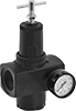
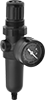
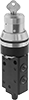
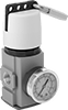
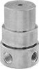
Pressure-Regulating Valves
Other Products