


System of Measurement System of Measurement |
|---|
|
Capacity Capacity | Show |
|---|
|
Capacity Capacity | Hide |
|---|
Mounting Orientation Mounting Orientation |
|---|
|
Maximum Pressure Maximum Pressure |
|---|
|
Material Material |
|---|
|
Finish Finish |
|---|
|
Mounting Plate Mounting Plate |
|---|
|
For Use With For Use With |
|---|
|
Specifications Met Specifications Met |
|---|
|
Mobility Mobility |
|---|
|
Liner Material Liner Material |
|---|
|
DFARS (Defense Acquisition Regulations Supplement) DFARS (Defense AcquisitionRegulations Supplement) |
|---|
Maximum Temperature Maximum Temperature |
|---|
|
Port Gender Port Gender |
|---|
|
RoHS (Restriction of Hazardous Substances) RoHS (Restriction ofHazardous Substances) |
|---|
|
REACH (Registration, Evaluation, Authorization and Restriction of Chemicals) REACH (Registration,Evaluation, Authorization and Restriction of Chemicals) |
|---|
|
ASME-Code Compressed Air Storage Tanks
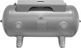
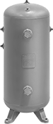
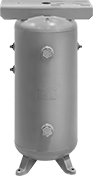
These tanks have drain ports on the bottom to remove condensation. All other ports can be used as inlets or outlets in any configuration.
Tanks with mounting plate have a platform where you can secure motors, pumps, and other components.
Steel tanks are primed or powder coated for exterior corrosion resistance. Epoxy-lined steel tanks also resist interior corrosion that can result from moisture in your compressed air.
Note: Per ASME code, all tanks are water tested. Those made without a corrosion-resistant coating or material will have rust on the interior.
![]() For technical drawings and 3-D models, click on a part number.
For technical drawings and 3-D models, click on a part number.
Ports | Overall | ||||||||||
|---|---|---|---|---|---|---|---|---|---|---|---|
| Cap., gal. | Max. Pressure, psi | Total No. of | Gender | Sizes | Lg. | Dia. | Ht. | Wall Thick. | Temp. Range, °F | Each | |
Horizontal with Mounting Plate | |||||||||||
Powder-Coated Steel | |||||||||||
| 80 | 200 | 9 | Female | 1/4 NPT Port (1 ea.) 3/4 NPT Port (1 ea.) 1 NPT Port (2 ea.) 1 1/4 NPT Port (1 ea.) 1 1/2 NPT Port (1 ea.) 2 NPT Port (2 ea.) 3/4 NPT Drain Port (1 ea.) | 63 5/8" | 20" | 25" | 1/8" | -20° to 400° | 0000000 | 000000000 |
Epoxy-Lined Powder-Coated Steel | |||||||||||
| 80 | 200 | 9 | Female | 1/4 NPT Port (1 ea.) 1 NPT Port (2 ea.) 1 1/2 NPT Port (3 ea.) 2 NPT Port (2 ea.) 3/4 NPT Drain Port (1 ea.) | 64" | 20" | 25" | 1/8" | -20° to 400° | 0000000 | 00000000 |
Vertical | |||||||||||
Powder-Coated Steel | |||||||||||
| 80 | 200 | 8 | Female | 1/4 NPT Port (1 ea.) 1 1/4 NPT Port (4 ea.) 2 NPT Port (2 ea.) 1/2 NPT Drain Port (1 ea.) | __ | 24" | 49 1/2" | 1/8" | -20° to 400° | 0000000 | 00000000 |
Epoxy-Lined Powder-Coated Steel | |||||||||||
| 80 | 200 | 8 | Female | 1/4 NPT Port (1 ea.) 1 1/4 NPT Port ( 3 ea.) 1 1/2 NPT Port (1 ea.) 2 NPT Port (2 ea.) 1 1/2 NPT Drain Port (1 ea.) | __ | 24" | 49 1/2" | 1/8" | -20° to 400° | 0000000 | 00000000 |
Vertical with Mounting Plate | |||||||||||
Powder-Coated Steel | |||||||||||
| 80 | 200 | 8 | Female | 1/4 NPT Port (1 ea.) 1 1/4 NPT Port (4 ea.) 2 NPT Port (2 ea.) 1 1/2 NPT Drain Port (1 ea.) | __ | 24" | 51" | 1/8" | -20° to 400° | 0000000 | 00000000 |
Epoxy-Lined Powder-Coated Steel | |||||||||||
| 80 | 200 | 8 | Female | 1/4 NPT Port (1 ea.) 1 1/4 NPT Port ( 3 ea.) 1 1/2 NPT Port (1 ea.) 2 NPT Port (2 ea.) 1 1/2 NPT Drain Port (1 ea.) | __ | 24" | 51" | 1/8" | -20° to 400° | 0000000 | 00000000 |
High-Pressure ASME-Code Compressed Air Storage Tanks
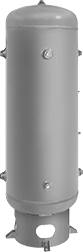
Able to withstand pressures up to 600 psi, these tanks store compressed air for use in high-pressure applications. They’re made of steel that's primed to resist exterior corrosion. Tanks have drain ports on the bottom to remove condensation. All other ports can be used as inlets or outlets in any configuration.
Note: Per ASME code, all tanks are water tested and will have rust on the interior.
![]() For technical drawings and 3-D models, click on a part number.
For technical drawings and 3-D models, click on a part number.
Ports | Overall | ||||||||||
|---|---|---|---|---|---|---|---|---|---|---|---|
| Cap., gal. | Max. Pressure, psi | Total No. of | Gender | Sizes | Dia. | Ht. | Wall Thick. | Temp. Range, °F | Specifications Met | Each | |
Vertical | |||||||||||
Gray Primed Steel | |||||||||||
| 80 | 600 | 8 | Female | 1/4 NPT Port (1 ea.) 1 1/4 NPT Port (4 ea.) 2 NPT Port (2 ea.) 1/2 NPT Drain Port (1 ea.) | 24" | 51 1/4" | 1/2" | -20° to 400° | ASME BPVC.VIII.1 | 000000 | 000000000 |
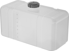
Rectangular Plastic Tanks
Store large quantities of liquid in these flat-bottomed tanks. They have vented fill caps so air can flow in and out.
80-gallon tanks require support bands (sold separately), which wrap around the center of tanks to maintain their shape.
![]() For technical drawings and 3-D models, click on a part number.
For technical drawings and 3-D models, click on a part number.
Drain | |||||||||||||||
|---|---|---|---|---|---|---|---|---|---|---|---|---|---|---|---|
| Cap., gal. | Wd. | Dp. | Ht. | Thick. | Fill Opening Dia. | Grad. Marks | Color | Clarity | Pipe Size | Gender | Max. Temp., °F | UV Protection | Includes | Each | |
Polyethylene Plastic | |||||||||||||||
| 80 | 27" | 18" | 40 1/4" | 1/4" | 5" | 10 gal. | White | Semi-Clear | 1 NPT | Female | 120° | UV Resistant | Vented Fill Cap | 0000000 | 0000000 |
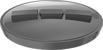
| For Fill Opening Dia. | Features | Each | |
Polypropylene Plastic | |||
|---|---|---|---|
| 5" | Vent | 0000000 | 000000 |
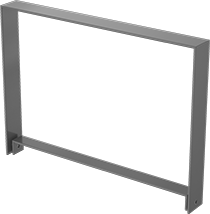
For Tank | Mounting Holes | ||||||
|---|---|---|---|---|---|---|---|
| Cap., gal. | Dp. | No. of | Dia. | Mounting Fasteners Included | Pkg. Qty. | Pkg. | |
Powder-Coated Steel | |||||||
| 80 | 18" | 2 | 7/16" | No | 1 | 0000000 | 000000 |
Stainless Steel Easy-Drain Tanks
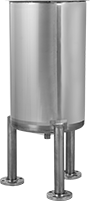
The bottom of these tanks is sloped to ensure easy and complete drainage.
For tanks with sanitary quick-clamp, see High-Polish Metal Quick-Clamp Sanitary Tube Fittings for compatible fittings.
![]() For technical drawings and 3-D models, click on a part number.
For technical drawings and 3-D models, click on a part number.
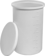
Round Plastic Batch Cans
| Capacity, gal. | Dia. | Ht. | Bottom ID | Thick. | Graduation Marks | Color | Clarity | Lid Type | Max. Temp., °F | Space Saving Features | Features | Each | |
Polyethylene Plastic | |||||||||||||
|---|---|---|---|---|---|---|---|---|---|---|---|---|---|
| 80 | 25 1/2" | 48" | 23 1/2" | 1/4" | 5 gal., 20 L | White | Semi-Clear | Loose Fitting | 140° | Stackable | Seamless | 0000000 | 0000000 |
Rubber and Plastic Tubs
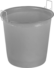
These tubs are crack and dent resistant.
![]() For technical drawings and 3-D models, click on a part number.
For technical drawings and 3-D models, click on a part number.
| Style | Capacity, gal. | Dia. | Ht. | Bottom ID | Thick. | Max. Temp., °F | Space Saving Features | Specifications Met | Color | Each | |
Polyethylene Plastic | |||||||||||
|---|---|---|---|---|---|---|---|---|---|---|---|
| C | 80 | 31 1/4" | 32" | 24" | 3/16" | Not Rated | Nestable | FDA Compliant 21 CFR 177.1520 | Orange | 0000000 | 0000000 |
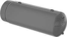
ASME-Code Expansion Tanks for Water
--7cc059f10c41610560320-p9@halfx_637461359604633535.png?ver=imagenotfound)
Manufactured in accordance with ASME BPVC.VIII.1, these tanks accommodate the expansion of heated water and provide a cushion of compressed air in closed water-heating systems. They prevent water loss by eliminating the need to expel hot water from systems during each heating cycle.
![]() For technical drawings and 3-D models, click on a part number.
For technical drawings and 3-D models, click on a part number.
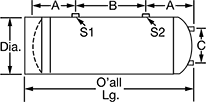
Tank End Connection Pipe Size | Tank Side Connection Pipe Size | ||||||||||||||||
|---|---|---|---|---|---|---|---|---|---|---|---|---|---|---|---|---|---|
| Capacity, gal. | Dia. | Overall Lg. | Lg. (A) | Lg. (B) | Lg. (C) | (E1) | (E2) | (S1) | (S2) | Pipe Connection Thread Type | Pipe Connection Gender | Wall Gauge, ga. | Max. Temp., °F | Max. Pressure, psi | Expansion Tank Type | Each | |
Gray-Painted Steel | |||||||||||||||||
| 80 | 20" | 64 5/16" | 10" | 42" | 16" | 1/2 | 1/2 | 2 | 2 | NPT | Female | 11 | 450° | 150 | Bladderless | 00000000 | 0000000 |