


Wire Connection Type Wire Connection Type | Show |
|---|
|
Wire Connection Type Wire Connection Type | Hide |
|---|
|
Type Type |
|---|
|
Mounting Location Mounting Location |
|---|
 | Panel |
Insulation Insulation |
|---|
| Fully Insulated | |
Splice Type Splice Type |
|---|
|
Wire Splicing Connector Style Wire Splicing Connector Style |
|---|
| Straight | |
Terminal Material Terminal Material |
|---|
|
RoHS (Restriction of Hazardous Substances) RoHS (Restriction ofHazardous Substances) |
|---|
|
Maximum Temperature Maximum Temperature |
|---|
|
Current Per Circuit Current Per Circuit |
|---|
|
Application Application |
|---|
|
DFARS (Defense Acquisition Regulations Supplement) DFARS (Defense AcquisitionRegulations Supplement) |
|---|
Terminal Finish Terminal Finish |
|---|
|
Insulation Material Insulation Material |
|---|
|
System of Measurement System of Measurement |
|---|
|
Width Width |
|---|
|
For Panel Cutout Height For Panel Cutout Height |
|---|
|
REACH (Registration, Evaluation, Authorization and Restriction of Chemicals) REACH (Registration,Evaluation, Authorization and Restriction of Chemicals) |
|---|
|
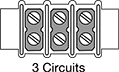
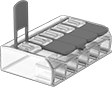
Through-Panel Terminal Blocks
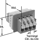
Make electrical connections through a panel—blocks mount in a cutout and have terminals on both sides. Rated UL 94 V-0, they meet flammability standards.
Lever-clamp terminals make installation and maintenance quick and convenient. Lower the lever to secure a wire; lift the lever to disconnect it.
![]() For technical drawings and 3-D models, click on a part number.
For technical drawings and 3-D models, click on a part number.
For Panel Cutout | |||||||||||
|---|---|---|---|---|---|---|---|---|---|---|---|
| No. of Circuits | For Wire Gauge | Terminal Ctr.-to-Ctr. | Lg. | Wd. | Ht. | Lg. | Ht. | Includes | Specifications Met | Each | |
Lever-Clamp Terminals | |||||||||||
600V AC/600V DC—40A Per Circuit | |||||||||||
| 4 | 16-6 | 7/16" | 2 9/16" | 2 13/16" | 1 15/16" | 2 1/16" | 1 1/4" | Mounting Clip | UL Recognized Component, CSA Certified, CE Marked, UL 94 V-0 | 0000000 | 000000 |
Clamp-On Wire Splicing Connectors


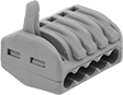
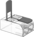
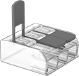
Press down on the clamp to connect wires and pull it up to disconnect.
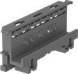
Clear connectors let you see that the wire is inserted properly and stripped to the correct length. They have two test slots—one on the front and one on the back—to test voltage even after the connectors are installed. Use a DIN rail adapter (sold separately) to mount these connectors to a 35 mm DIN rail.
![]() For technical drawings and 3-D models, click on a part number.
For technical drawings and 3-D models, click on a part number.
Connectors | DIN Rail Adapters | |||||||||||||
|---|---|---|---|---|---|---|---|---|---|---|---|---|---|---|
| For No. of Wires | For Wire Gauge | Lever Color | Insulation Material | Terminal Material | Max. Voltage | Max. Temp., °F | Specifications Met | Features | Pkg. Qty. | Pkg. | Pkg. Qty. | Pkg. | ||
Gray Connectors | ||||||||||||||
| 2 | 28-12 | Orange | Polycarbonate Plastic | Tin-Plated Copper | 600V AC 600V DC | 185° | UL Listed | __ | 5 | 000000 | 00000 | __ | 000000 | 00 |
| 3 | 28-12 | Orange | Polycarbonate Plastic | Tin-Plated Copper | 600V AC 600V DC | 185° | UL Listed | __ | 5 | 000000 | 0000 | __ | 000000 | 00 |
| 5 | 28-12 | Orange | Polycarbonate Plastic | Tin-Plated Copper | 600V AC 600V DC | 185° | UL Listed | __ | 5 | 000000 | 0000 | __ | 000000 | 00 |
Clear Connectors | ||||||||||||||
| 2 | 24-12 | Orange | Polycarbonate Plastic | Tin-Plated Copper | 600V AC 600V DC | 185° | UL Listed | Two Test Slots | 10 | 0000000 | 0000 | 10 | 0000000 | 000000 |
| 3 | 24-12 | Orange | Polycarbonate Plastic | Tin-Plated Copper | 600V AC 600V DC | 185° | UL Listed | Two Test Slots | 10 | 0000000 | 0000 | 10 | 0000000 | 00000 |
| 5 | 24-12 | Orange | Polycarbonate Plastic | Tin-Plated Copper | 600V AC 600V DC | 185° | UL Listed | Two Test Slots | 10 | 0000000 | 00000 | 10 | 0000000 | 00000 |