


Filter by
Barrel Diameter
Head Diameter
Overall Length
Barrel Length
Current
Wire Connection Method
Finish
Maximum Spring Force
Compressed Length
Initial Spring Force
U.S.–Mexico–Canada Agreement (USMCA) Qualifying
Wire Connection
DFARS Specialty Metals
Export Control Classification Number (ECCN)
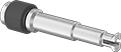
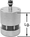
Spring Test Probes
Round Tip | 90° Cup Tip | |
 | ||
Flat Tip | Waffle Tip | Crown Tip |
 | ||
30° Spear Tip | Chisel Tip | 90° Razor Tip |
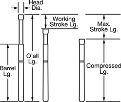 | ||
Spring Force, ozf | Stroke Lg. | Barrel | |||||||||||||||||||||||||||||||||||||||||||||||||||||||||||||||||||||||||||||||||||||||||||||||||
|---|---|---|---|---|---|---|---|---|---|---|---|---|---|---|---|---|---|---|---|---|---|---|---|---|---|---|---|---|---|---|---|---|---|---|---|---|---|---|---|---|---|---|---|---|---|---|---|---|---|---|---|---|---|---|---|---|---|---|---|---|---|---|---|---|---|---|---|---|---|---|---|---|---|---|---|---|---|---|---|---|---|---|---|---|---|---|---|---|---|---|---|---|---|---|---|---|---|---|---|
Min. Spacing Between Probe Centers | Current, amp | Initial | Max. | Overall Lg. | Compressed Lg. | Working | Max. | Lg. | Dia. | Head Dia. | Finish | Pkg. Qty. | Pkg. | ||||||||||||||||||||||||||||||||||||||||||||||||||||||||||||||||||||||||||||||||||||||
Round Tip | |||||||||||||||||||||||||||||||||||||||||||||||||||||||||||||||||||||||||||||||||||||||||||||||||||
| 0.039" | 4.3 | 2.2 | 5.4 | 1.435" | 1.27" | 0.167" | 1/4" | 1.435" | 0.024" | 0.016" | Gold Plated | 5 | 5949T159 | 000000 | |||||||||||||||||||||||||||||||||||||||||||||||||||||||||||||||||||||||||||||||||||||
| 0.05" | 3 | 2.4 | 7 | 1.7" | 1.45" | 0.167" | 1/4" | 1.43" | 0.031" | 0.021" | Gold Plated | 5 | 5949T136 | 00000 | |||||||||||||||||||||||||||||||||||||||||||||||||||||||||||||||||||||||||||||||||||||
| 0.05" | 5 | 1.7 | 7 | 1.865" | 1.548" | 0.317" | 0.35" | 1.43" | 0.031" | 0.021" | Gold Plated | 5 | 5949T153 | 00000 | |||||||||||||||||||||||||||||||||||||||||||||||||||||||||||||||||||||||||||||||||||||
| 0.05" | 5 | 2.4 | 5.6 | 1.36" | 1.12" | 0.167" | 1/4" | 1.09" | 0.031" | 0.021" | Gold Plated | 5 | 5949T125 | 00000 | |||||||||||||||||||||||||||||||||||||||||||||||||||||||||||||||||||||||||||||||||||||
| 0.05" | 5.9 | 1.2 | 4.8 | 1.527" | 1.21" | 0.317" | 0.4" | 1.09" | 0.031" | 0.021" | Gold Plated | 5 | 5949T15 | 00000 | |||||||||||||||||||||||||||||||||||||||||||||||||||||||||||||||||||||||||||||||||||||
| 0.075" | 10 | 1.7 | 7 | 1.45" | 1.13" | 0.317" | 0.35" | 1" | 0.04" | 0.026" | Gold Plated | 5 | 5949T145 | 00000 | |||||||||||||||||||||||||||||||||||||||||||||||||||||||||||||||||||||||||||||||||||||
| 0.075" | 11 | 2.7 | 7 | 1.3" | 1.05" | 0.167" | 1/4" | 1" | 0.04" | 0.026" | Gold Plated | 5 | 5949T109 | 00000 | |||||||||||||||||||||||||||||||||||||||||||||||||||||||||||||||||||||||||||||||||||||
| 0.1" | 14 | 2 | 7 | 1.46" | 1.14" | 0.317" | 0.35" | 1" | 0.054" | 0.036" | Gold Plated | 5 | 5949T117 | 00000 | |||||||||||||||||||||||||||||||||||||||||||||||||||||||||||||||||||||||||||||||||||||
| 0.1" | 17 | 2.6 | 6.5 | 1.31" | 1.06" | 0.167" | 1/4" | 1" | 0.054" | 0.036" | Gold Plated | 5 | 5949T99 | 00000 | |||||||||||||||||||||||||||||||||||||||||||||||||||||||||||||||||||||||||||||||||||||
| 0.125" | 5 | 2.9 | 7 | 1.3" | 1.05" | 0.17" | 1/4" | 0.97" | 0.08" | 0.059" | Gold Plated | 5 | 5949T133 | 00000 | |||||||||||||||||||||||||||||||||||||||||||||||||||||||||||||||||||||||||||||||||||||
| 0.125" | 27 | 2.9 | 7 | 1.3" | 1.05" | 0.17" | 1/4" | 0.97" | 0.08" | 0.059" | Gold Plated | 5 | 5949T143 | 00000 | |||||||||||||||||||||||||||||||||||||||||||||||||||||||||||||||||||||||||||||||||||||
| 0.187" | 32 | 4 | 10 | 1.33" | 1.07" | 0.17" | 1/4" | 0.97" | 0.09" | 0.068" | Gold Plated | 5 | 5949T164 | 00000 | |||||||||||||||||||||||||||||||||||||||||||||||||||||||||||||||||||||||||||||||||||||
90° Cup Tip | |||||||||||||||||||||||||||||||||||||||||||||||||||||||||||||||||||||||||||||||||||||||||||||||||||
| 0.05" | 3 | 0.6 | 2.5 | 0.66" | 0.56" | 0.07" | 0.1" | 0.52" | 0.03" | 0.04" | Gold Plated | 5 | 5949T61 | 00000 | |||||||||||||||||||||||||||||||||||||||||||||||||||||||||||||||||||||||||||||||||||||
| 0.05" | 3 | 2.4 | 7 | 1.7" | 1.45" | 0.167" | 1/4" | 1.43" | 0.031" | 0.035" | Gold Plated | 5 | 5949T138 | 00000 | |||||||||||||||||||||||||||||||||||||||||||||||||||||||||||||||||||||||||||||||||||||
| 0.05" | 5 | 2.4 | 5.6 | 1.36" | 1.12" | 0.167" | 1/4" | 1.09" | 0.031" | 0.035" | Gold Plated | 5 | 5949T127 | 00000 | |||||||||||||||||||||||||||||||||||||||||||||||||||||||||||||||||||||||||||||||||||||
| 0.075" | 3 | 1.5 | 3.8 | 0.67" | 0.55" | 0.07" | 0.1" | 0.49" | 0.04" | 0.06" | Gold Plated | 5 | 5949T65 | 00000 | |||||||||||||||||||||||||||||||||||||||||||||||||||||||||||||||||||||||||||||||||||||
| 0.075" | 11 | 2.7 | 7 | 1.3" | 1.05" | 0.167" | 1/4" | 1" | 0.04" | 0.046" | Gold Plated | 5 | 5949T111 | 00000 | |||||||||||||||||||||||||||||||||||||||||||||||||||||||||||||||||||||||||||||||||||||
| 0.1" | 12 | 2.2 | 5.5 | 0.97" | 0.89" | 0.107" | 0.16" | 0.73" | 0.054" | 0.075" | Gold Plated | 5 | 5949T74 | 00000 | |||||||||||||||||||||||||||||||||||||||||||||||||||||||||||||||||||||||||||||||||||||
| 0.1" | 14 | 2 | 7 | 1.46" | 1.14" | 0.317" | 0.35" | 1" | 0.054" | 0.062" | Gold Plated | 5 | 5949T119 | 00000 | |||||||||||||||||||||||||||||||||||||||||||||||||||||||||||||||||||||||||||||||||||||
| 0.1" | 17 | 2.6 | 6.5 | 1.31" | 1.06" | 0.167" | 1/4" | 1" | 0.054" | 0.062" | Gold Plated | 5 | 5949T102 | 00000 | |||||||||||||||||||||||||||||||||||||||||||||||||||||||||||||||||||||||||||||||||||||
| 0.125" | 23 | 2.2 | 7 | 1.3" | 1.22" | 0.167" | 1/4" | 0.97" | 0.08" | 0.1" | Gold Plated | 5 | 5949T81 | 00000 | |||||||||||||||||||||||||||||||||||||||||||||||||||||||||||||||||||||||||||||||||||||
| 0.125" | 41 | 2.2 | 7 | 1.3" | 1.22" | 0.167" | 1/4" | 0.97" | 0.08" | 0.1" | Gold Plated | 5 | 5949T84 | 00000 | |||||||||||||||||||||||||||||||||||||||||||||||||||||||||||||||||||||||||||||||||||||
| 0.187" | 5 | 2.8 | 7 | 1.33" | 1.08" | 0.17" | 1/4" | 0.97" | 0.09" | 0.16" | Gold Plated | 5 | 5949T31 | 00000 | |||||||||||||||||||||||||||||||||||||||||||||||||||||||||||||||||||||||||||||||||||||
| 0.187" | 5 | 2.8 | 16.4 | 1.42" | 1.17" | 0.17" | 1/4" | 1.07" | 0.13" | 0.16" | Gold Plated | 5 | 5949T41 | 00000 | |||||||||||||||||||||||||||||||||||||||||||||||||||||||||||||||||||||||||||||||||||||
| 0.187" | 32 | 4 | 10 | 1.33" | 1.07" | 0.17" | 1/4" | 0.97" | 0.09" | 0.16" | Gold Plated | 5 | 5949T165 | 00000 | |||||||||||||||||||||||||||||||||||||||||||||||||||||||||||||||||||||||||||||||||||||
| 0.187" | 43 | 2.2 | 6 | 1.32" | 1.07" | 0.167" | 1/4" | 0.97" | 0.093" | 0.155" | Gold Plated | 5 | 5949T87 | 00000 | |||||||||||||||||||||||||||||||||||||||||||||||||||||||||||||||||||||||||||||||||||||
| 0.187" | 55 | 7 | 18 | 1.42" | 1.17" | 0.167" | 1/4" | 1.07" | 0.125" | 0.155" | Gold Plated | 5 | 5949T96 | 00000 | |||||||||||||||||||||||||||||||||||||||||||||||||||||||||||||||||||||||||||||||||||||
Flat Tip | |||||||||||||||||||||||||||||||||||||||||||||||||||||||||||||||||||||||||||||||||||||||||||||||||||
| 0.05" | 3 | 2.4 | 7 | 1.7" | 1.45" | 0.167" | 1/4" | 1.43" | 0.031" | 0.035" | Gold Plated | 5 | 5949T135 | 00000 | |||||||||||||||||||||||||||||||||||||||||||||||||||||||||||||||||||||||||||||||||||||
| 0.05" | 5 | 2.4 | 5.6 | 1.36" | 1.12" | 0.167" | 1/4" | 1.09" | 0.031" | 0.035" | Gold Plated | 5 | 5949T124 | 00000 | |||||||||||||||||||||||||||||||||||||||||||||||||||||||||||||||||||||||||||||||||||||
| 0.075" | 10 | 1.7 | 7 | 1.45" | 1.13" | 0.317" | 0.35" | 1" | 0.04" | 0.026" | Gold Plated | 5 | 5949T144 | 00000 | |||||||||||||||||||||||||||||||||||||||||||||||||||||||||||||||||||||||||||||||||||||
| 0.075" | 11 | 2.7 | 7 | 1.3" | 1.05" | 0.167" | 1/4" | 1" | 0.04" | 0.046" | Gold Plated | 5 | 5949T108 | 00000 | |||||||||||||||||||||||||||||||||||||||||||||||||||||||||||||||||||||||||||||||||||||
| 0.1" | 14 | 2 | 7 | 1.46" | 1.14" | 0.317" | 0.35" | 1" | 0.054" | 0.062" | Gold Plated | 5 | 5949T116 | 00000 | |||||||||||||||||||||||||||||||||||||||||||||||||||||||||||||||||||||||||||||||||||||
| 0.1" | 17 | 2.6 | 6.5 | 1.31" | 1.06" | 0.167" | 1/4" | 1" | 0.054" | 0.062" | Gold Plated | 5 | 5949T98 | 00000 | |||||||||||||||||||||||||||||||||||||||||||||||||||||||||||||||||||||||||||||||||||||
| 0.125" | 5 | 2.9 | 7 | 1.3" | 1.05" | 0.17" | 1/4" | 0.97" | 0.08" | 0.1" | Gold Plated | 5 | 5949T132 | 00000 | |||||||||||||||||||||||||||||||||||||||||||||||||||||||||||||||||||||||||||||||||||||
| 0.187" | 32 | 4 | 10 | 1.33" | 1.07" | 0.17" | 1/4" | 0.97" | 0.09" | 0.16" | Gold Plated | 5 | 5949T163 | 00000 | |||||||||||||||||||||||||||||||||||||||||||||||||||||||||||||||||||||||||||||||||||||
| 0.187" | 39 | 7.2 | 18.7 | 1.42" | 1.17" | 0.17" | 1/4" | 1.07" | 0.13" | 0.16" | Gold Plated | 5 | 5949T169 | 00000 | |||||||||||||||||||||||||||||||||||||||||||||||||||||||||||||||||||||||||||||||||||||
Waffle Tip | |||||||||||||||||||||||||||||||||||||||||||||||||||||||||||||||||||||||||||||||||||||||||||||||||||
| 0.05" | 3 | 0.6 | 2.5 | 0.66" | 0.56" | 0.07" | 0.1" | 0.52" | 0.03" | 0.04" | Gold Plated | 5 | 5949T63 | 00000 | |||||||||||||||||||||||||||||||||||||||||||||||||||||||||||||||||||||||||||||||||||||
| 0.05" | 3 | 2.4 | 7 | 1.7" | 1.45" | 0.167" | 1/4" | 1.43" | 0.031" | 0.035" | Gold Plated | 5 | 5949T139 | 00000 | |||||||||||||||||||||||||||||||||||||||||||||||||||||||||||||||||||||||||||||||||||||
| 0.05" | 5 | 2.4 | 5.6 | 1.36" | 1.12" | 0.167" | 1/4" | 1.09" | 0.031" | 0.035" | Gold Plated | 5 | 5949T128 | 00000 | |||||||||||||||||||||||||||||||||||||||||||||||||||||||||||||||||||||||||||||||||||||
| 0.075" | 3 | 1.5 | 3.8 | 0.67" | 0.55" | 0.07" | 0.1" | 0.49" | 0.04" | 0.06" | Gold Plated | 5 | 5949T67 | 00000 | |||||||||||||||||||||||||||||||||||||||||||||||||||||||||||||||||||||||||||||||||||||
| 0.075" | 10 | 1.7 | 7 | 1.45" | 1.13" | 0.317" | 0.35" | 1" | 0.04" | 0.046" | Gold Plated | 5 | 5949T147 | 00000 | |||||||||||||||||||||||||||||||||||||||||||||||||||||||||||||||||||||||||||||||||||||
| 0.075" | 11 | 2.7 | 7 | 1.3" | 1.05" | 0.167" | 1/4" | 1" | 0.04" | 0.046" | Gold Plated | 5 | 5949T112 | 00000 | |||||||||||||||||||||||||||||||||||||||||||||||||||||||||||||||||||||||||||||||||||||
| 0.1" | 12 | 2.2 | 5.5 | 0.97" | 0.89" | 0.107" | 0.16" | 0.73" | 0.054" | 0.075" | Gold Plated | 5 | 5949T76 | 00000 | |||||||||||||||||||||||||||||||||||||||||||||||||||||||||||||||||||||||||||||||||||||
| 0.1" | 14 | 2 | 7 | 1.46" | 1.14" | 0.317" | 0.35" | 1" | 0.054" | 0.062" | Gold Plated | 5 | 5949T12 | 00000 | |||||||||||||||||||||||||||||||||||||||||||||||||||||||||||||||||||||||||||||||||||||
| 0.1" | 17 | 2.6 | 6.5 | 1.31" | 1.06" | 0.167" | 1/4" | 1" | 0.054" | 0.062" | Gold Plated | 5 | 5949T103 | 00000 | |||||||||||||||||||||||||||||||||||||||||||||||||||||||||||||||||||||||||||||||||||||
| 0.125" | 23 | 2.2 | 7 | 1.3" | 1.22" | 0.167" | 1/4" | 0.97" | 0.08" | 0.1" | Gold Plated | 5 | 5949T83 | 00000 | |||||||||||||||||||||||||||||||||||||||||||||||||||||||||||||||||||||||||||||||||||||
| 0.125" | 41 | 2.2 | 7 | 1.3" | 1.22" | 0.167" | 1/4" | 0.97" | 0.08" | 0.1" | Gold Plated | 5 | 5949T85 | 00000 | |||||||||||||||||||||||||||||||||||||||||||||||||||||||||||||||||||||||||||||||||||||
| 0.187" | 5 | 2.8 | 7 | 1.33" | 1.08" | 0.17" | 1/4" | 0.97" | 0.09" | 0.16" | Gold Plated | 5 | 5949T33 | 00000 | |||||||||||||||||||||||||||||||||||||||||||||||||||||||||||||||||||||||||||||||||||||
| 0.187" | 5 | 2.8 | 16.4 | 1.42" | 1.17" | 0.17" | 1/4" | 1.07" | 0.13" | 0.16" | Gold Plated | 5 | 5949T43 | 00000 | |||||||||||||||||||||||||||||||||||||||||||||||||||||||||||||||||||||||||||||||||||||
| 0.187" | 43 | 2.2 | 6 | 1.32" | 1.07" | 0.167" | 1/4" | 0.97" | 0.093" | 0.155" | Gold Plated | 5 | 5949T89 | 00000 | |||||||||||||||||||||||||||||||||||||||||||||||||||||||||||||||||||||||||||||||||||||
| 0.187" | 55 | 7 | 18 | 1.42" | 1.17" | 0.167" | 1/4" | 1.07" | 0.125" | 0.155" | Gold Plated | 5 | 5949T97 | 00000 | |||||||||||||||||||||||||||||||||||||||||||||||||||||||||||||||||||||||||||||||||||||
Crown Tip | |||||||||||||||||||||||||||||||||||||||||||||||||||||||||||||||||||||||||||||||||||||||||||||||||||
| 0.039" | 4.3 | 2.2 | 5.4 | 1.435" | 1.27" | 0.167" | 1/4" | 1.135" | 0.024" | 0.016" | Gold Plated | 5 | 5949T162 | 00000 | |||||||||||||||||||||||||||||||||||||||||||||||||||||||||||||||||||||||||||||||||||||
| 0.05" | 5 | 1.7 | 7 | 1.865" | 1.548" | 0.317" | 0.35" | 1.43" | 0.031" | 0.021" | Gold Plated | 5 | 5949T158 | 00000 | |||||||||||||||||||||||||||||||||||||||||||||||||||||||||||||||||||||||||||||||||||||
| 0.1" | 17 | 2.6 | 6.5 | 1.31" | 1.06" | 0.167" | 1/4" | 1" | 0.054" | 0.036" | Gold Plated | 5 | 5949T105 | 00000 | |||||||||||||||||||||||||||||||||||||||||||||||||||||||||||||||||||||||||||||||||||||
| 0.125" | 5 | 2.9 | 7 | 1.3" | 1.05" | 0.17" | 1/4" | 0.97" | 0.08" | 0.066" | Gold Plated | 5 | 5949T134 | 00000 | |||||||||||||||||||||||||||||||||||||||||||||||||||||||||||||||||||||||||||||||||||||
30° Spear Tip | |||||||||||||||||||||||||||||||||||||||||||||||||||||||||||||||||||||||||||||||||||||||||||||||||||
| 0.025" | 2 | 0.5 | 1.6 | 1.17" | 1.01" | 0.107" | 0.16" | 1" | 0.016" | 0.009" | Gold Plated | 5 | 5949T167 | 00000 | |||||||||||||||||||||||||||||||||||||||||||||||||||||||||||||||||||||||||||||||||||||
| 0.05" | 3 | 0.6 | 2.5 | 0.66" | 0.56" | 0.07" | 0.1" | 0.52" | 0.03" | 0.02" | Gold Plated | 5 | 5949T62 | 00000 | |||||||||||||||||||||||||||||||||||||||||||||||||||||||||||||||||||||||||||||||||||||
| 0.05" | 3 | 2.4 | 7 | 1.7" | 1.45" | 0.167" | 1/4" | 1.43" | 0.031" | 0.021" | Gold Plated | 5 | 5949T137 | 00000 | |||||||||||||||||||||||||||||||||||||||||||||||||||||||||||||||||||||||||||||||||||||
| 0.05" | 5 | 2.4 | 5.6 | 1.36" | 1.12" | 0.167" | 1/4" | 1.09" | 0.031" | 0.021" | Gold Plated | 5 | 5949T126 | 00000 | |||||||||||||||||||||||||||||||||||||||||||||||||||||||||||||||||||||||||||||||||||||
| 0.075" | 3 | 1.5 | 3.8 | 0.67" | 0.55" | 0.07" | 0.1" | 0.49" | 0.04" | 0.03" | Gold Plated | 5 | 5949T66 | 00000 | |||||||||||||||||||||||||||||||||||||||||||||||||||||||||||||||||||||||||||||||||||||
| 0.075" | 10 | 1.7 | 7 | 1.45" | 1.13" | 0.317" | 0.35" | 1" | 0.04" | 0.026" | Gold Plated | 5 | 5949T146 | 00000 | |||||||||||||||||||||||||||||||||||||||||||||||||||||||||||||||||||||||||||||||||||||
| 0.075" | 11 | 2.7 | 7 | 1.3" | 1.05" | 0.167" | 1/4" | 1" | 0.04" | 0.026" | Gold Plated | 5 | 5949T11 | 00000 | |||||||||||||||||||||||||||||||||||||||||||||||||||||||||||||||||||||||||||||||||||||
| 0.1" | 12 | 2.2 | 5.5 | 0.97" | 0.89" | 0.107" | 0.16" | 0.73" | 0.054" | 0.04" | Gold Plated | 5 | 5949T75 | 00000 | |||||||||||||||||||||||||||||||||||||||||||||||||||||||||||||||||||||||||||||||||||||
| 0.1" | 14 | 2 | 7 | 1.46" | 1.14" | 0.317" | 0.35" | 1" | 0.054" | 0.036" | Gold Plated | 5 | 5949T118 | 00000 | |||||||||||||||||||||||||||||||||||||||||||||||||||||||||||||||||||||||||||||||||||||
| 0.1" | 17 | 2.6 | 6.5 | 1.31" | 1.06" | 0.167" | 1/4" | 1" | 0.054" | 0.036" | Gold Plated | 5 | 5949T101 | 00000 | |||||||||||||||||||||||||||||||||||||||||||||||||||||||||||||||||||||||||||||||||||||
| 0.125" | 23 | 2.2 | 7 | 1.3" | 1.22" | 0.167" | 1/4" | 0.97" | 0.08" | 0.059" | Gold Plated | 5 | 5949T82 | 00000 | |||||||||||||||||||||||||||||||||||||||||||||||||||||||||||||||||||||||||||||||||||||
| 0.156" | 5 | 2.8 | 7 | 1.33" | 1.07" | 0.17" | 1/4" | 0.97" | 0.09" | 0.08" | Gold Plated | 5 | 5949T32 | 00000 | |||||||||||||||||||||||||||||||||||||||||||||||||||||||||||||||||||||||||||||||||||||
| 0.187" | 5 | 2.8 | 16.4 | 1.42" | 1.17" | 0.17" | 1/4" | 1.07" | 0.13" | 0.094" | Gold Plated | 5 | 5949T168 | 00000 | |||||||||||||||||||||||||||||||||||||||||||||||||||||||||||||||||||||||||||||||||||||
Chisel Tip | |||||||||||||||||||||||||||||||||||||||||||||||||||||||||||||||||||||||||||||||||||||||||||||||||||
| 0.05" | 3 | 2.4 | 7 | 1.7" | 1.45" | 0.167" | 1/4" | 1.43" | 0.031" | 0.021" | Gold Plated | 5 | 5949T14 | 00000 | |||||||||||||||||||||||||||||||||||||||||||||||||||||||||||||||||||||||||||||||||||||
| 0.075" | 11 | 2.7 | 7 | 1.3" | 1.05" | 0.167" | 1/4" | 1" | 0.04" | 0.026" | Gold Plated | 5 | 5949T113 | 00000 | |||||||||||||||||||||||||||||||||||||||||||||||||||||||||||||||||||||||||||||||||||||
| 0.1" | 14 | 2 | 7 | 1.46" | 1.14" | 0.317" | 0.35" | 1" | 0.054" | 0.036" | Gold Plated | 5 | 5949T121 | 00000 | |||||||||||||||||||||||||||||||||||||||||||||||||||||||||||||||||||||||||||||||||||||
| 0.1" | 17 | 2.6 | 6.5 | 1.31" | 1.06" | 0.167" | 1/4" | 1" | 0.054" | 0.036" | Gold Plated | 5 | 5949T107 | 00000 | |||||||||||||||||||||||||||||||||||||||||||||||||||||||||||||||||||||||||||||||||||||
| 0.125" | 5 | 2.9 | 7 | 1.3" | 1.05" | 0.17" | 1/4" | 0.97" | 0.08" | 0.1" | Gold Plated | 5 | 5949T104 | 00000 | |||||||||||||||||||||||||||||||||||||||||||||||||||||||||||||||||||||||||||||||||||||
90° Razor Tip | |||||||||||||||||||||||||||||||||||||||||||||||||||||||||||||||||||||||||||||||||||||||||||||||||||
| 0.039" | 4 | 1.8 | 6 | 1.585" | 1.268" | 0.317" | 0.4" | 1.135" | 0.024" | 0.016" | Gold Plated | 5 | 5949T166 | 00000 | |||||||||||||||||||||||||||||||||||||||||||||||||||||||||||||||||||||||||||||||||||||
| 0.039" | 4.3 | 2.2 | 5.4 | 1.435" | 1.27" | 0.167" | 1/4" | 1.135" | 0.024" | 0.016" | Gold Plated | 5 | 5949T16 | 00000 | |||||||||||||||||||||||||||||||||||||||||||||||||||||||||||||||||||||||||||||||||||||
| 0.05" | 3 | 2.4 | 7 | 1.7" | 1.45" | 0.167" | 1/4" | 1.43" | 0.031" | 0.021" | Gold Plated | 5 | 5949T142 | 00000 | |||||||||||||||||||||||||||||||||||||||||||||||||||||||||||||||||||||||||||||||||||||
| 0.075" | 11 | 2.7 | 7 | 1.3" | 1.05" | 0.167" | 1/4" | 1" | 0.04" | 0.026" | Gold Plated | 5 | 5949T114 | 00000 | |||||||||||||||||||||||||||||||||||||||||||||||||||||||||||||||||||||||||||||||||||||
| 0.1" | 14 | 2 | 7 | 1.46" | 1.14" | 0.317" | 0.35" | 1" | 0.054" | 0.036" | Gold Plated | 5 | 5949T123 | 00000 | |||||||||||||||||||||||||||||||||||||||||||||||||||||||||||||||||||||||||||||||||||||
| 0.1" | 17 | 2.6 | 6.5 | 1.31" | 1.06" | 0.167" | 1/4" | 1" | 0.054" | 0.036" | Gold Plated | 5 | 5949T106 | 00000 | |||||||||||||||||||||||||||||||||||||||||||||||||||||||||||||||||||||||||||||||||||||
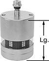
Spring Test Probe Sockets
Quick-Disconnect-Terminal Jack |
Quick-Disconnect-Terminal Plug |
Post-Terminal Wraparound Connection |
Solder Connection |
 |
Mount these sockets to fixtures, attach wire from your electrical testing equipment, and add Spring Test Probes to create automated systems to test continuity in circuit boards. Use a probe that has the same minimum spacing between probe centers and has the specified barrel length. Test probes and sockets are sold separately.
When installing test probes and sockets, adhere to the "minimum spacing between probe centers" to maximize testing points while preventing probes from interfering with each other.
Quick-Disconnect-Terminal Wire Connection—Sockets with a quick-disconnect terminal connection require an adapter (sold separately) to quickly and easily connect and disconnect your wire from the socket terminal. All of these sockets click in place for a hold that’s more secure than wraparound wire terminal connections, but less secure than solder connections. They also have sleeving for electrical insulation.
Jack—Sockets with a jack have a lower profile and offer a more secure hold than those with a plug. Use a crimper (not included) to install wire onto the adapter. These sockets can’t be reused due to their crimped connection.
Plug—Sockets with a plug offer the fastest wire installation time. Simply slide the plug over the wire and barbs will grip the wire sleeving—no need for crimpers. These sockets can be reused. They are not, however, as secure as those with a jack because their hold can loosen over time.
Solder Connection—For sockets with a solder connection, place wire onto the cupped terminal on the socket and solder to create a metallic bond that is stronger than quick-disconnect and wraparound wire terminal connections. Add additional sheathing, such as heat-shrink tubing (not included), for electrical insulation.
Wraparound Connection—For sockets with a wraparound wire terminal connection, install wire by winding it around the squared terminal on the socket. Their connection is not as secure as quick-disconnect terminal and solder connections. Add additional sheathing, such as heat-shrink tubing (not included), for electrical insulation.
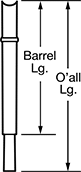
Barrel | |||||||||||||||||||||||||||||||||||||||||||||||||||||||||||||||||||||||||||||||||||||||||||||||||||
|---|---|---|---|---|---|---|---|---|---|---|---|---|---|---|---|---|---|---|---|---|---|---|---|---|---|---|---|---|---|---|---|---|---|---|---|---|---|---|---|---|---|---|---|---|---|---|---|---|---|---|---|---|---|---|---|---|---|---|---|---|---|---|---|---|---|---|---|---|---|---|---|---|---|---|---|---|---|---|---|---|---|---|---|---|---|---|---|---|---|---|---|---|---|---|---|---|---|---|---|
For Min. Spacing Between Probe Ctr. | For Probe Barrel Lg. | For Mounting Hole Dia. | For Wire Ga. | Overall Lg. | Lg. | Dia. | Finish | Pkg. Qty. | Pkg. | ||||||||||||||||||||||||||||||||||||||||||||||||||||||||||||||||||||||||||||||||||||||||||
Quick-Disconnect-Terminal Jack | |||||||||||||||||||||||||||||||||||||||||||||||||||||||||||||||||||||||||||||||||||||||||||||||||||
| 0.039" | 1.135" | 0.031" | 30, 28 | 1.235" | 1.235" | 0.032" | Gold Plated | 5 | 4203N19 | 000000 | |||||||||||||||||||||||||||||||||||||||||||||||||||||||||||||||||||||||||||||||||||||||||
| 0.05" | 1.09" | 0.038" | 30, 28 | 1.262" | 1.095" | 0.038" | Nickel Plated | 5 | 4203N21 | 00000 | |||||||||||||||||||||||||||||||||||||||||||||||||||||||||||||||||||||||||||||||||||||||||
| 0.05" | 1.43" | 0.038" | 30, 28 | 1.6" | 1.433" | 0.038" | Nickel Plated | 5 | 4203N22 | 00000 | |||||||||||||||||||||||||||||||||||||||||||||||||||||||||||||||||||||||||||||||||||||||||
Quick-Disconnect-Terminal Plug | |||||||||||||||||||||||||||||||||||||||||||||||||||||||||||||||||||||||||||||||||||||||||||||||||||
| 0.05" | 1.09" | 0.038" | 30, 28 | 1.262" | 1.095" | 0.038" | Nickel Plated | 5 | 4203N17 | 00000 | |||||||||||||||||||||||||||||||||||||||||||||||||||||||||||||||||||||||||||||||||||||||||
| 0.05" | 1.43" | 0.038" | 30, 28 | 1.6" | 1.433" | 0.038" | Nickel Plated | 5 | 4203N18 | 00000 | |||||||||||||||||||||||||||||||||||||||||||||||||||||||||||||||||||||||||||||||||||||||||
Post-Terminal Wraparound Connection | |||||||||||||||||||||||||||||||||||||||||||||||||||||||||||||||||||||||||||||||||||||||||||||||||||
| 0.05" | 1.09" | 0.038" | 36, 32, 30 | 1.345" | 1.095" | 0.038" | Nickel Plated | 5 | 4203N12 | 00000 | |||||||||||||||||||||||||||||||||||||||||||||||||||||||||||||||||||||||||||||||||||||||||
| 0.05" | 1.43" | 0.038" | 36, 32, 30 | 1.683" | 1.433" | 0.038" | Nickel Plated | 5 | 4203N13 | 00000 | |||||||||||||||||||||||||||||||||||||||||||||||||||||||||||||||||||||||||||||||||||||||||
| 0.075" | 1" | 0.053" | 32, 30, 28, 26 | 1.499" | 1.07" | 0.052" | — | 5 | 4203N14 | 00000 | |||||||||||||||||||||||||||||||||||||||||||||||||||||||||||||||||||||||||||||||||||||||||
| 0.1" | 1" | 0.067" | 32, 30, 28, 26 | 1.509" | 1.08" | 0.066" | — | 5 | 4203N15 | 0000 | |||||||||||||||||||||||||||||||||||||||||||||||||||||||||||||||||||||||||||||||||||||||||
| 0.125" | 0.97" | 0.094" | 32, 30, 28, 26 | 1.509" | 1.08" | 0.093" | — | 5 | 4203N16 | 00000 | |||||||||||||||||||||||||||||||||||||||||||||||||||||||||||||||||||||||||||||||||||||||||
Solder Connection | |||||||||||||||||||||||||||||||||||||||||||||||||||||||||||||||||||||||||||||||||||||||||||||||||||
| 0.05" | 0.52" | 0.036" | 30, 29, 28 | 0.7" | 0.5" | 0.03" | Gold Plated | 5 | 5949T64 | 0000 | |||||||||||||||||||||||||||||||||||||||||||||||||||||||||||||||||||||||||||||||||||||||||
| 0.075" | 0.49" | 0.056" | 28, 27, 26, 25, 24 | 0.7" | 0.49" | 0.05" | Gold Plated | 5 | 5949T68 | 0000 | |||||||||||||||||||||||||||||||||||||||||||||||||||||||||||||||||||||||||||||||||||||||||
| 0.075" | 1" | 0.053" | 28, 26, 24, 20 | 1.17" | 0.99" | 0.052" | — | 5 | 4203N11 | 0000 | |||||||||||||||||||||||||||||||||||||||||||||||||||||||||||||||||||||||||||||||||||||||||
| 0.1" | 0.73" | 0.069" | 26, 25, 24, 23, 22 | 0.9" | 0.72" | 0.07" | — | 5 | 5949T77 | 0000 | |||||||||||||||||||||||||||||||||||||||||||||||||||||||||||||||||||||||||||||||||||||||||
| 0.125" | 0.97" | 0.095" | 26, 25, 24, 22 | 1.2" | 0.97" | 0.09" | — | 5 | 5949T86 | 0000 | |||||||||||||||||||||||||||||||||||||||||||||||||||||||||||||||||||||||||||||||||||||||||
| 0.125" | 0.97" | 0.095" | 20, 19, 18, 17, 16 | 1.2" | 0.97" | 0.09" | Gold Plated | 5 | 5949T93 | 00000 | |||||||||||||||||||||||||||||||||||||||||||||||||||||||||||||||||||||||||||||||||||||||||
| 0.156", 0.187" | 0.97" | 0.109" | 26, 25, 24, 22 | 1.22" | 1" | 0.11" | Gold Plated | 5 | 5949T362 | 0000 | |||||||||||||||||||||||||||||||||||||||||||||||||||||||||||||||||||||||||||||||||||||||||
| 0.187" | 0.97" | 0.109" | 20, 19, 18, 17, 16 | 1.2" | 0.97" | 0.11" | Gold Plated | 5 | 5949T94 | 00000 | |||||||||||||||||||||||||||||||||||||||||||||||||||||||||||||||||||||||||||||||||||||||||
| 0.187" | 1.07" | 0.142" | 26, 25, 24, 23, 22 | 1.3" | 1.1" | 0.14" | Gold Plated | 5 | 5949T462 | 0000 | |||||||||||||||||||||||||||||||||||||||||||||||||||||||||||||||||||||||||||||||||||||||||
| 0.187" | 1.07" | 0.142" | 20, 19, 18, 17, 16 | 1.31" | 1.06" | 0.14" | Gold Plated | 5 | 5949T95 | 00000 | |||||||||||||||||||||||||||||||||||||||||||||||||||||||||||||||||||||||||||||||||||||||||
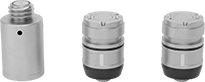
Coordinate Measurement Machine Probes for CNC Lathes
Probes
 |
Coordinate Measurement Machine Probes | Replacement Batteries | ||||||||||||||||||||||||||||||||||||||||||||||||||||||||||||||||||||||||||||||||||||||||||||||||||
|---|---|---|---|---|---|---|---|---|---|---|---|---|---|---|---|---|---|---|---|---|---|---|---|---|---|---|---|---|---|---|---|---|---|---|---|---|---|---|---|---|---|---|---|---|---|---|---|---|---|---|---|---|---|---|---|---|---|---|---|---|---|---|---|---|---|---|---|---|---|---|---|---|---|---|---|---|---|---|---|---|---|---|---|---|---|---|---|---|---|---|---|---|---|---|---|---|---|---|---|
For Stylus | Trigger Force, N | ||||||||||||||||||||||||||||||||||||||||||||||||||||||||||||||||||||||||||||||||||||||||||||||||||
Dia., mm | Lg., mm | Thread Size | O'all Lg., mm | For Axis Measuring Direction | X- and Y-Axis | Z-Axis | Repeatability, mm | Max. Distance from Receiver, m | Enclosure Rating | Manufacturer (Series) | Each | Pkg. Qty. | Pkg. | ||||||||||||||||||||||||||||||||||||||||||||||||||||||||||||||||||||||||||||||||||||||
Infrared | |||||||||||||||||||||||||||||||||||||||||||||||||||||||||||||||||||||||||||||||||||||||||||||||||||
| 40 | 58 | M4 | 50 to 150 | ±X, ±Y, +Z | 0.4, 0.8 | 5.3 | -0.001 to 0.001 | 5 | IK02, IP08 | Renishaw (OLP40) | 6192N11 | 000000000 | 1 | 6951K59 | 00000 | ||||||||||||||||||||||||||||||||||||||||||||||||||||||||||||||||||||||||||||||||||||
Radio | |||||||||||||||||||||||||||||||||||||||||||||||||||||||||||||||||||||||||||||||||||||||||||||||||||
| 40 | 58 | M4 | 50 to 150 | ±X, ±Y, +Z | 0.6, 0.97 | 6.23 | -0.001 to 0.001 | 15 | IK02, IP08 | Renishaw (RLP40-QE) | 6192N12 | 00000000 | 1 | 6951K59 | 0000 | ||||||||||||||||||||||||||||||||||||||||||||||||||||||||||||||||||||||||||||||||||||
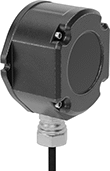 |
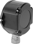
Receiver |
For Infrared Probes—Infrared probes send data to a receiver up to 5 meters away, but because they use light, they need a clear view. These probes are typically found in small lathes with chuck sizes around 8” and medium lathes with chuck sizes around 15”. They can also be used on a 5-axis CNC with a table size under 1,500 mm.
Component | For Max. No. of Probes | Wire Connection | Cord Lg., ft. | Manufacturer (Series) | Each | ||||||||||||||||||||||||||||||||||||||||||||||||||||||||||||||||||||||||||||||||||||||||||||||
|---|---|---|---|---|---|---|---|---|---|---|---|---|---|---|---|---|---|---|---|---|---|---|---|---|---|---|---|---|---|---|---|---|---|---|---|---|---|---|---|---|---|---|---|---|---|---|---|---|---|---|---|---|---|---|---|---|---|---|---|---|---|---|---|---|---|---|---|---|---|---|---|---|---|---|---|---|---|---|---|---|---|---|---|---|---|---|---|---|---|---|---|---|---|---|---|---|---|---|---|
For Infrared Probes | |||||||||||||||||||||||||||||||||||||||||||||||||||||||||||||||||||||||||||||||||||||||||||||||||||
| Receiver | 4 | Wire Leads | 82 | Renishaw (OMM-2) | 6206N13 | 000000000 | |||||||||||||||||||||||||||||||||||||||||||||||||||||||||||||||||||||||||||||||||||||||||||||
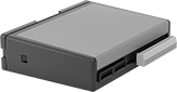 |
Interface |
Component | Wire Connection | Manufacturer (Series) | Each | ||||||||||||||||||||||||||||||||||||||||||||||||||||||||||||||||||||||||||||||||||||||||||||||||
|---|---|---|---|---|---|---|---|---|---|---|---|---|---|---|---|---|---|---|---|---|---|---|---|---|---|---|---|---|---|---|---|---|---|---|---|---|---|---|---|---|---|---|---|---|---|---|---|---|---|---|---|---|---|---|---|---|---|---|---|---|---|---|---|---|---|---|---|---|---|---|---|---|---|---|---|---|---|---|---|---|---|---|---|---|---|---|---|---|---|---|---|---|---|---|---|---|---|---|---|
For Infrared Probes | |||||||||||||||||||||||||||||||||||||||||||||||||||||||||||||||||||||||||||||||||||||||||||||||||||
| Interface | Screw Terminal | Renishaw (OSI) | 6206N14 | 000000000 | |||||||||||||||||||||||||||||||||||||||||||||||||||||||||||||||||||||||||||||||||||||||||||||||
 |
Receiver/Interface |
For Infrared Probes—Infrared probes send data to a receiver up to 5 meters away, but because they use light, they need a clear view. These probes are typically found in small lathes with chuck sizes around 8” and medium lathes with chuck sizes around 15”. They can also be used on a 5-axis CNC with a table size under 1,500 mm.
For Radio Probes—Radio probes send data to a receiver up to 15 meters away. They block out interference from other radio devices, so you can use multiple radio probes in one machine shop. They’re used in small, medium, and large lathes with a chuck size up to 24". They can also be used on a 5-axis CNC with a table size under 3,500 mm.
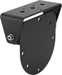 |
Receiver mounting brackets make it easy to attach a receiver or receiver/interface to your lathe.
Color | Material | Mounting Fasteners Included | Mfr. | Mfr. Model No. | Each | ||
|---|---|---|---|---|---|---|---|
| Black | Powder-Coated Steel | Yes | Renishaw | A-2033-0830 | 6206N21 | 0000000 |
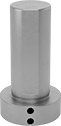 |
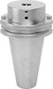
Use a shank to attach a probe to the spindle on your CNC lathe.
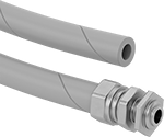 |
Conduit Trade Size | Cord Lg., ft. | Mfr. | Mfr. Model No. | Each | ||
|---|---|---|---|---|---|---|
| 5/16 | 3 | Renishaw | A-4113-0306 | 6206N15 | 000000 |
Coordinate Measurement Machine Probes for CNC Machines
Probes
 |
Infrared—Infrared probes send data to a receiver up to 5 meters away, but because they use light, they need a clear view.
Radio— Radio probes send data to a receiver up to 15 meters away. They block out interference from other radio devices, so you can use multiple radio probes in one machine shop.
40 mm Diameter—40 mm probes are typically found in small and medium machines with a chuck size between 6" and 15".
63 mm Diameter—63 mm probes are typically found in medium to large machines with a chuck size between 10" and 24".
Coordinate Measurement Machine Probes | Replacement Batteries | ||||||||||||||||||||||||||||||||||||||||||||||||||||||||||||||||||||||||||||||||||||||||||||||||||
|---|---|---|---|---|---|---|---|---|---|---|---|---|---|---|---|---|---|---|---|---|---|---|---|---|---|---|---|---|---|---|---|---|---|---|---|---|---|---|---|---|---|---|---|---|---|---|---|---|---|---|---|---|---|---|---|---|---|---|---|---|---|---|---|---|---|---|---|---|---|---|---|---|---|---|---|---|---|---|---|---|---|---|---|---|---|---|---|---|---|---|---|---|---|---|---|---|---|---|---|
For Stylus | Trigger Force, N | ||||||||||||||||||||||||||||||||||||||||||||||||||||||||||||||||||||||||||||||||||||||||||||||||||
Dia., mm | Lg., mm | Thread Size | O'all Lg., mm | For Axis Measuring Direction | X- and Y-Axis | Z-Axis | Repeatability, mm | Max. Distance from Receiver, m | Enclosure Rating | Manufacturer (Series) | Each | Pkg. Qty. | Pkg. | ||||||||||||||||||||||||||||||||||||||||||||||||||||||||||||||||||||||||||||||||||||||
Infrared | |||||||||||||||||||||||||||||||||||||||||||||||||||||||||||||||||||||||||||||||||||||||||||||||||||
| 40 | 50 | M4 | 50 to 150 | ±X, ±Y, +Z | 0.5, 0.9 | 5.85 | -0.001 to 0.001 | 5 | IK01, IP08 | Renishaw (OMP40) | 6206N11 | 000000000 | 1 | 6951K59 | 00000 | ||||||||||||||||||||||||||||||||||||||||||||||||||||||||||||||||||||||||||||||||||||
| 63 | 76 | M4 | 50 to 150 | ±X, ±Y, +Z | 0.75, 1.4 | 5.3 | -0.001 to 0.001 | 6 | IP08 | Renishaw (OMP60) | 6206N12 | 00000000 | 1 | 6951K57 | 0000 | ||||||||||||||||||||||||||||||||||||||||||||||||||||||||||||||||||||||||||||||||||||
Radio | |||||||||||||||||||||||||||||||||||||||||||||||||||||||||||||||||||||||||||||||||||||||||||||||||||
| 40 | 50 | M4 | 50 to 150 | ±X, ±Y, +Z | 0.5, 0.9 | 5.85 | -0.001 to 0.001 | 15 | IK01, IP08 | Renishaw (RMP40-QE) | 6206N17 | 00000000 | 1 | 6951K59 | 0000 | ||||||||||||||||||||||||||||||||||||||||||||||||||||||||||||||||||||||||||||||||||||
| 63 | 76 | M4 | 50 to 150 | ±X, ±Y, +Z | 0.75, 1.4 | 5.3 | -0.001 to 0.001 | 15 | IP08 | Renishaw (RMP60-QE) | 6206N18 | 00000000 | 1 | 6951K57 | 0000 | ||||||||||||||||||||||||||||||||||||||||||||||||||||||||||||||||||||||||||||||||||||
|
Receiver |
For Infrared Probes—Infrared probes send data to a receiver up to 5 meters away, but because they use light, they need a clear view.
Component | For Max. No. of Probes | Wire Connection | Cord Lg., ft. | Manufacturer (Series) | Each | ||||||||||||||||||||||||||||||||||||||||||||||||||||||||||||||||||||||||||||||||||||||||||||||
|---|---|---|---|---|---|---|---|---|---|---|---|---|---|---|---|---|---|---|---|---|---|---|---|---|---|---|---|---|---|---|---|---|---|---|---|---|---|---|---|---|---|---|---|---|---|---|---|---|---|---|---|---|---|---|---|---|---|---|---|---|---|---|---|---|---|---|---|---|---|---|---|---|---|---|---|---|---|---|---|---|---|---|---|---|---|---|---|---|---|---|---|---|---|---|---|---|---|---|---|
For Infrared Probes | |||||||||||||||||||||||||||||||||||||||||||||||||||||||||||||||||||||||||||||||||||||||||||||||||||
| Receiver | 4 | Wire Leads | 82 | Renishaw (OMM-2) | 6206N13 | 000000000 | |||||||||||||||||||||||||||||||||||||||||||||||||||||||||||||||||||||||||||||||||||||||||||||
|
Interface |
Component | Wire Connection | Manufacturer (Series) | Each | ||||||||||||||||||||||||||||||||||||||||||||||||||||||||||||||||||||||||||||||||||||||||||||||||
|---|---|---|---|---|---|---|---|---|---|---|---|---|---|---|---|---|---|---|---|---|---|---|---|---|---|---|---|---|---|---|---|---|---|---|---|---|---|---|---|---|---|---|---|---|---|---|---|---|---|---|---|---|---|---|---|---|---|---|---|---|---|---|---|---|---|---|---|---|---|---|---|---|---|---|---|---|---|---|---|---|---|---|---|---|---|---|---|---|---|---|---|---|---|---|---|---|---|---|---|
For Infrared Probes | |||||||||||||||||||||||||||||||||||||||||||||||||||||||||||||||||||||||||||||||||||||||||||||||||||
| Interface | Screw Terminal | Renishaw (OSI) | 6206N14 | 000000000 | |||||||||||||||||||||||||||||||||||||||||||||||||||||||||||||||||||||||||||||||||||||||||||||||
|
Receiver/Interface |
For Infrared Probes—Infrared probes send data to a receiver up to 5 meters away, but because they use light, they need a clear view.
For Radio Probes— Radio probes send data to a receiver up to 15 meters away. They block out interference from other radio devices, so you can use multiple radio probes in one machine shop.
|
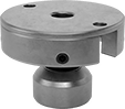
Receiver mounting brackets make it easy to attach a receiver or receiver/interface to your machine.
Color | Material | Mounting Fasteners Included | Mfr. | Mfr. Model No. | Each | ||
|---|---|---|---|---|---|---|---|
| Black | Powder-Coated Steel | Yes | Renishaw | A-2033-0830 | 6206N21 | 0000000 |
 |
For Probe Dia., mm | Shank Type | For Probe Mfr. Series | Mfr. | Mfr. Model No. | Each | ||
|---|---|---|---|---|---|---|---|
| 40 | BT 40 Taper | OMP40, RMP40-QE | Renishaw | M-4071-0057 | 6206N26 | 0000000 | |
| 40 | BT 50 Taper | OMP40, RMP40-QE | Renishaw | M-4071-0071 | 6206N27 | 000000 | |
| 40 | CAT 40 Taper | OMP40, RMP40-QE | Renishaw | M-4071-0058 | 6206N22 | 000000 | |
| 40 | CAT 50 Taper | OMP40, RMP40-QE | Renishaw | M-4071-0072 | 6206N23 | 000000 | |
| 63 | BT 40 Taper | OMP60, RMP60-QE | Renishaw | M-2045-0027 | 6206N28 | 000000 | |
| 63 | BT 50 Taper | OMP60, RMP60-QE | Renishaw | M-2045-0073 | 6206N29 | 000000 | |
| 63 | CAT 40 Taper | OMP60, RMP60-QE | Renishaw | M-2045-0069 | 6206N24 | 000000 | |
| 63 | CAT 50 Taper | OMP60, RMP60-QE | Renishaw | M-2045-0071 | 6206N25 | 000000 |
 |
Add a shank adapter to fit 40 mm probes to shanks made for 63 mm probes.
For Probe Manufacturer Series | Compatible with Shanks for Probe Manufacturer Series | Mfr. | Mfr. Model No. | Each | ||
|---|---|---|---|---|---|---|
| OMP40, RMP40-QE | MP11, MP12, MP700, MP700E, OMP60, RMP60-QE | Renishaw | A-4071-0031 | 6206N16 | 0000000 |
|
Conduit Trade Size | Cord Lg., ft. | Mfr. | Mfr. Model No. | Each | ||
|---|---|---|---|---|---|---|
| 5/16 | 3 | Renishaw | A-4113-0306 | 6206N15 | 000000 |
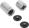
Modular Coordinate Measurement Machine Probes
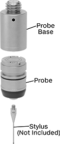 |
Probe Base and Probe Sold Separately |
Swap out Renishaw probe styles to inspect different features on a part without having to recalibrate. These probes mount magnetically to a base that threads into your coordinate measuring machine (CMM), making mid-inspection changes quick. They’re also known as modules. It’s easy to tell different styles apart from their different end colors. To take 3D measurements, they record the coordinates of different points on your workpiece. Because this involves physically touching your workpiece, they’re more accurate than other automated measurement systems. They’re touch-trigger probes, the most common CMM probe type, which means they stop to record the coordinates of one point at a time. Use them to check distances, diameters, right angles, and the location of holes and grooves. However, they're not as good at checking complex features, flatness, or roundness.
All probes require a stylus as well as a base (sold separately for some probes).
Trigger force is the amount of force required for a probe to take a measurement and record it. Choose a probe with a force that is high enough to avoid false triggers from vibration but not so high it damages the workpiece and leads to inaccurate measurements.
Probe and Base Kits
 |
SF Series—SF series probes have a trigger force that works for most general purpose probing jobs where vibration is not an issue.
TP20 Series—TP20 probe bases have a magnetic proximity switch to prevent a probe from accidentally triggering when you’re attaching it or detaching it. However, probes attached to these bases can’t be used to inspect magnetic parts.
For Stylus | Trigger Force, N | |||||||||||||
|---|---|---|---|---|---|---|---|---|---|---|---|---|---|---|
No. of Pieces | Includes | Dia., mm | Thread Size | O'all Lg., mm | For Axis Measuring Direction | X- and Y-Axis | Z-Axis | End Color | Features | Manufacturer (Series) | Each | |||
| 3 | Two 20 mm Lg. SF Probes One 19 mm Lg. TP20 Probe Base | 13 | M2 | 10 to 50 | ±X, ±Y, +Z | 0.08 | 0.75 | Black | Magnetic Proximity Switch | Renishaw (SF, TP20) | 6179N11 | 000000000 | ||
 |
For Probe Mfr. Series | Mfr. | Mfr. Model No. | Each | ||
|---|---|---|---|---|---|
| TP20, TP20 NI | Renishaw | A-1042-1486 | 6179N23 | 000000 |
Probe Bases
Bases house the system that sends a signal to record a measurement. They thread onto probe heads with an M8 connection on your CMM.
TP20 Series—TP20 probe bases have a magnetic proximity switch to prevent a probe from accidentally triggering when you’re attaching it or detaching it. However, probes attached to these bases can’t be used to inspect magnetic parts.
TP20 NI Series—TP20 NI probe bases aren’t affected by magnetic fields, so they can be used to inspect magnetic parts. However, because they don’t have a magnetic proximity switch, you’ll need to program your CMM to stop taking measurements when you’re changing out probes.
Probes
For Stylus | Trigger Force, N | ||||||||||||||||||||||||||||||||||||||||||||||||||||||||||||||||||||||||||||||||||||||||||||||||||
|---|---|---|---|---|---|---|---|---|---|---|---|---|---|---|---|---|---|---|---|---|---|---|---|---|---|---|---|---|---|---|---|---|---|---|---|---|---|---|---|---|---|---|---|---|---|---|---|---|---|---|---|---|---|---|---|---|---|---|---|---|---|---|---|---|---|---|---|---|---|---|---|---|---|---|---|---|---|---|---|---|---|---|---|---|---|---|---|---|---|---|---|---|---|---|---|---|---|---|---|
Dia., mm | Lg., mm | Thread Size | O'all Lg., mm | For Axis Measuring Direction | X- and Y-Axis | Z-Axis | End Color | Each | |||||||||||||||||||||||||||||||||||||||||||||||||||||||||||||||||||||||||||||||||||||||||||
Renishaw (LF) | |||||||||||||||||||||||||||||||||||||||||||||||||||||||||||||||||||||||||||||||||||||||||||||||||||
| 13 | 20 | M2 | 10 to 30 | ±X, ±Y, +Z | 0.055 | 0.65 | Green | 6179N17 | 000000000 | ||||||||||||||||||||||||||||||||||||||||||||||||||||||||||||||||||||||||||||||||||||||||||
Renishaw (SF) | |||||||||||||||||||||||||||||||||||||||||||||||||||||||||||||||||||||||||||||||||||||||||||||||||||
| 13 | 20 | M2 | 10 to 50 | ±X, ±Y, +Z | 0.08 | 0.75 | Black | 6179N14 | 00000000 | ||||||||||||||||||||||||||||||||||||||||||||||||||||||||||||||||||||||||||||||||||||||||||
| 13 | 70 | M2 | 10 to 50 | ±X, ±Y, +Z | 0.08 | 0.75 | Black | 6179N19 | 00000000 | ||||||||||||||||||||||||||||||||||||||||||||||||||||||||||||||||||||||||||||||||||||||||||
| 13 | 95 | M2 | 10 to 50 | ±X, ±Y, +Z | 0.08 | 0.75 | Black | 6179N21 | 00000000 | ||||||||||||||||||||||||||||||||||||||||||||||||||||||||||||||||||||||||||||||||||||||||||
Renishaw (6W) | |||||||||||||||||||||||||||||||||||||||||||||||||||||||||||||||||||||||||||||||||||||||||||||||||||
| 13 | 24 | M2 | 10 to 30 | ±X, ±Y, ±Z | 0.14 | 1.6 | Blue | 6179N18 | 00000000 | ||||||||||||||||||||||||||||||||||||||||||||||||||||||||||||||||||||||||||||||||||||||||||
Renishaw (MF) | |||||||||||||||||||||||||||||||||||||||||||||||||||||||||||||||||||||||||||||||||||||||||||||||||||
| 13 | 20 | M2 | 10 to 60 | ±X, ±Y, +Z | 0.1 | 1.9 | Gray | 6179N15 | 00000000 | ||||||||||||||||||||||||||||||||||||||||||||||||||||||||||||||||||||||||||||||||||||||||||
Renishaw (EF) | |||||||||||||||||||||||||||||||||||||||||||||||||||||||||||||||||||||||||||||||||||||||||||||||||||
| 13 | 20 | M2 | 10 to 60 | ±X, ±Y, +Z | 0.1 | 3.2 | Brown | 6179N16 | 00000000 | ||||||||||||||||||||||||||||||||||||||||||||||||||||||||||||||||||||||||||||||||||||||||||
|
For Probe Mfr. Series | Mfr. | Mfr. Model No. | Each | ||
|---|---|---|---|---|---|
| TP20, TP20 NI | Renishaw | A-1042-1486 | 6179N23 | 000000 |
Modular Scanning Coordinate Measurement Machine Probes
Probe and Base Kits
 |  |
For Stylus | ||||||||||
|---|---|---|---|---|---|---|---|---|---|---|
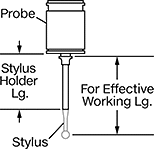
No. of Pieces | Includes | For Effective Working Lg., mm | Thread Size | O'all Lg., mm | For Axis Measuring Direction | Manufacturer (Series) | Each | |||
| 4 | One SM25-1 Probe Two SH25-1 Stylus Holders One SP25M Probe Base | 20 to 50 | M3 | 20 to 50 | ±X, ±Y, ±Z | Renishaw (SM25-1, SH25-1, SP25M) | 6191N11 | 0000000000 | ||
Probe Bases
Dia., mm | Lg., mm | Manufacturer (Series) | Each | |||
|---|---|---|---|---|---|---|
| 25 | 46 | Renishaw (SP25M) | 6191N24 | 000000000 | ||
Probes
 |  | |
Stylus Holder | Probe |
Non-Linear Scanning Probes—Non-linear scanning probes work with angled styli and star styli, which probe in multiple directions.
Coordinate Measurement Machine Probes | Stylus Holders | ||||||||||||||||||||||||||||||||||||||||||||||||||||||||||||||||||||||||||||||||||||||||||||||||||
|---|---|---|---|---|---|---|---|---|---|---|---|---|---|---|---|---|---|---|---|---|---|---|---|---|---|---|---|---|---|---|---|---|---|---|---|---|---|---|---|---|---|---|---|---|---|---|---|---|---|---|---|---|---|---|---|---|---|---|---|---|---|---|---|---|---|---|---|---|---|---|---|---|---|---|---|---|---|---|---|---|---|---|---|---|---|---|---|---|---|---|---|---|---|---|---|---|---|---|---|
For Stylus | |||||||||||||||||||||||||||||||||||||||||||||||||||||||||||||||||||||||||||||||||||||||||||||||||||
For Effective Working Lg., mm | Dia., mm | Lg., mm | Thread Size | O'all Lg., mm | For Axis Measuring Direction | Manufacturer (Series) | Each | Lg., mm | Each | ||||||||||||||||||||||||||||||||||||||||||||||||||||||||||||||||||||||||||||||||||||||||||
Coordinate Measurement Machine Probes | |||||||||||||||||||||||||||||||||||||||||||||||||||||||||||||||||||||||||||||||||||||||||||||||||||
| 20 to 50 | 25 | 26 | M3 | 20 to 50 | ±X, ±Y, ±Z | Renishaw (SM25-1) | 6191N13 | 000000000 | 2.3 | 6191N18 | 0000000 | ||||||||||||||||||||||||||||||||||||||||||||||||||||||||||||||||||||||||||||||||||||||||
| 50 to 105 | 25 | 34 | M3 | 20 to 75 | ±X, ±Y, ±Z | Renishaw (SM25-2) | 6191N14 | 00000000 | 32.2 | 6191N19 | 000000 | ||||||||||||||||||||||||||||||||||||||||||||||||||||||||||||||||||||||||||||||||||||||||
| 120 to 200 | 25 | 48 | M3 | 20 to 100 | ±X, ±Y, ±Z | Renishaw (SM25-3) | 6191N15 | 00000000 | 102.2 | 6191N21 | 000000 | ||||||||||||||||||||||||||||||||||||||||||||||||||||||||||||||||||||||||||||||||||||||||
| 220 to 400 | 25 | 63 | M3 | 20 to 200 | ±X, ±Y, ±Z | Renishaw (SM25-4) | 6191N16 | 00000000 | 202.3 | 6191N22 | 000000 | ||||||||||||||||||||||||||||||||||||||||||||||||||||||||||||||||||||||||||||||||||||||||
Non-Linear Scanning Probes | |||||||||||||||||||||||||||||||||||||||||||||||||||||||||||||||||||||||||||||||||||||||||||||||||||
| 10 to 100 | 25 | 39 | M3 | 10 to 100 | ±X, ±Y, ±Z | Renishaw (SM25-5) | 6191N17 | 00000000 | 2.7 | 6191N23 | 000000 | ||||||||||||||||||||||||||||||||||||||||||||||||||||||||||||||||||||||||||||||||||||||||
Touch-Trigger Probe Adapters
 |
Dia., mm | Lg., mm | For Probe Mfr. Series | Manufacturer (Series) | Each | |||
|---|---|---|---|---|---|---|---|
| 25 | 17 | LF, SF, 6W, MF, EF | Renishaw (TM25-20) | 6191N12 | 000000000 | ||
