


Filter by
Body Thread Size
Actuation Type

Thread Size
Extended Length
Actuation Mechanism
Energy Capacity
Retracted Length

Bumper Material
Body Material
Rod Material
Body Diameter
DFARS Specialty Metals
Export Control Classification Number (ECCN)
Miniature Threaded-Body Air Cylinders
Single Acting%20--%3e%3csvg%20version='1.1'%20id='Layer_1'%20xmlns='http://www.w3.org/2000/svg'%20xmlns:xlink='http://www.w3.org/1999/xlink'%20x='0px'%20y='0px'%20viewBox='0%200%20400%20400'%20style='enable-background:new%200%200%20400%20400;'%20xml:space='preserve'%3e%3cstyle%20type='text/css'%3e%20.st0{fill:%231A70A0;}%20.st1{opacity:0.5;}%20%3c/style%3e%3cg%3e%3cg%3e%3cpath%20class='st0'%20d='M200,56.9c38.35,0,74.4,14.93,101.51,42.05c27.11,27.11,42.05,63.17,42.05,101.51s-14.93,74.4-42.05,101.51%20S238.35,344.02,200,344.02s-74.4-14.93-101.51-42.05c-27.11-27.11-42.05-63.17-42.05-101.51s14.93-74.4,42.05-101.51%20S161.65,56.9,200,56.9%20M200,12.9C96.41,12.9,12.44,96.88,12.44,200.46c0,103.59,83.97,187.56,187.56,187.56%20c103.59,0,187.56-83.97,187.56-187.56C387.56,96.88,303.59,12.9,200,12.9L200,12.9z'/%3e%3c/g%3e%3cg%3e%3cg%20class='st1'%3e%3cpath%20class='st0'%20d='M235.49,152.24h16.15l-27.46,111.87c-1.94,7.8-2.91,12.5-2.91,14.1c0,1.82,0.58,3.29,1.73,4.41%20c1.16,1.12,2.69,1.68,4.61,1.68c5.23,0,11.78-3.85,19.63-11.55l17.22,21.34c-16.95,17.33-34.87,26-53.78,26%20c-8.37,0-15.45-1.47-21.23-4.41c-5.79-2.94-10.44-7.25-13.95-12.92c-3.51-5.67-5.27-11.18-5.27-16.53c0-1.93,0.35-5.24,1.05-9.94%20c1-6.94,2.05-12.54,3.15-16.82l15.22-62.15h-32.69l7.65-30.97C190.89,163.58,214.53,158.88,235.49,152.24z%20M230.44,80.84%20c8.24,0,14.66,2.62,19.26,7.86c4.6,5.24,6.9,11.55,6.9,18.94c0,5.46-1.42,10.7-4.25,15.73c-2.83,5.03-6.88,9.07-12.12,12.12%20c-5.24,3.05-10.33,4.57-15.24,4.57c-4.6,0-9.17-1.23-13.72-3.69c-4.55-2.46-8.02-5.78-10.43-9.95%20c-2.41-4.17-3.61-8.67-3.61-13.48c0-5.35,1.52-10.64,4.57-15.89c3.05-5.24,7.03-9.25,11.96-12.04%20C218.68,82.23,224.24,80.84,230.44,80.84z'/%3e%3c/g%3e%3cg%3e%3cpath%20class='st0'%20d='M214.08,152.24h16.15l-27.46,111.87c-1.94,7.8-2.91,12.5-2.91,14.1c0,1.82,0.58,3.29,1.73,4.41%20c1.16,1.12,2.69,1.68,4.61,1.68c5.23,0,11.78-3.85,19.63-11.55l17.22,21.34c-16.95,17.33-34.87,26-53.78,26%20c-8.37,0-15.45-1.47-21.23-4.41c-5.79-2.94-10.44-7.25-13.95-12.92c-3.51-5.67-5.27-11.18-5.27-16.53c0-1.93,0.35-5.24,1.05-9.94%20c1-6.94,2.05-12.54,3.15-16.82l15.22-62.15h-32.69l7.65-30.97C169.48,163.58,193.11,158.88,214.08,152.24z%20M209.03,80.84%20c8.24,0,14.66,2.62,19.26,7.86c4.6,5.24,6.9,11.55,6.9,18.94c0,5.46-1.42,10.7-4.25,15.73c-2.83,5.03-6.88,9.07-12.12,12.12%20c-5.24,3.05-10.33,4.57-15.24,4.57c-4.6,0-9.17-1.23-13.72-3.69c-4.55-2.46-8.02-5.78-10.43-9.95%20c-2.41-4.17-3.61-8.67-3.61-13.48c0-5.35,1.52-10.64,4.57-15.89c3.05-5.24,7.03-9.25,11.96-12.04%20C197.26,82.23,202.83,80.84,209.03,80.84z'/%3e%3c/g%3e%3c/g%3e%3c/g%3e%3c/svg%3e)
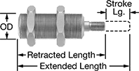 |
Single-acting cylinders are push style—air extends the rod and cylinders have a spring that returns the rod to its original position.
Lg. | Air Inlet | ||||||||||
|---|---|---|---|---|---|---|---|---|---|---|---|
Stroke | Retracted | Extended | Force @ 100 psi, lbf | Body Material | Thread Size | Thread Type | Gender | Each | |||
1/4" Bore (3/8" OD) | |||||||||||
| 1/4" | 1.57" | 1.8" | 5 | Brass | 10-32 | UNF | Female | 6604K11 | 000000 | ||
| 1/2" | 1.8" | 2.3" | 5 | Brass | 10-32 | UNF | Female | 6604K31 | 000000 | ||
3/8" Bore (1/2" OD) | |||||||||||
| 1/4" | 1.74" | 1.99" | 11 | Brass | 10-32 | UNF | Female | 6604K32 | 000000 | ||
| 3/8" | 1.87" | 2.24" | 11 | Brass | 10-32 | UNF | Female | 6604K33 | 000000 | ||
| 1/2" | 1.99" | 2.49" | 11 | Brass | 10-32 | UNF | Female | 6604K13 | 000000 | ||
| 1" | 2.49" | 3.49" | 11 | Brass | 10-32 | UNF | Female | 6604K34 | 000000 | ||
1/2" Bore (5/8" OD) | |||||||||||
| 1/2" | 2.05" | 2.55" | 20 | Brass | 10-32 | UNF | Female | 6604K15 | 000000 | ||
| 3/4" | 2.3" | 3.05" | 20 | Brass | 10-32 | UNF | Female | 6604K36 | 000000 | ||
| 1" | 2.55" | 3.55" | 20 | Brass | 10-32 | UNF | Female | 6604K37 | 000000 | ||
Double Acting
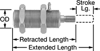 |
Double-acting cylinders exert force in both directions.
Lg. | Rear Air Inlet | Side Port | ||||||||||||||||
|---|---|---|---|---|---|---|---|---|---|---|---|---|---|---|---|---|---|---|
Stroke | Retracted | Extended | Force @ 100 psi, lbf | Body Material | Connection | For Tube ID | Thread Size | Thread Type | Gender | Connection | For Tube ID | Thread Size | Thread Type | Gender | Each | |||
1/4" Bore (3/8" OD) | ||||||||||||||||||
| 1/4" | 1.57" | 1.8" | 5 | Brass | Threaded | — | 10-32 | UNF | Female | Barbed | 1/16" | — | — | Male | 6604K21 | 0000000 | ||
| 1/2" | 1.8" | 2.3" | 5 | Brass | Threaded | — | 10-32 | UNF | Female | Barbed | 1/16" | — | — | Male | 6604K38 | 000000 | ||
| 3/4" | 2.05" | 2.8" | 5 | Brass | Barbed | 1/16" | — | — | Male | Barbed | 1/16" | — | — | Male | 6604K39 | 000000 | ||
| 1" | 2.3" | 3.3" | 5 | Brass | Threaded | — | 10-32 | UNF | Female | Barbed | 1/16" | — | — | Male | 6604K41 | 000000 | ||
3/8" Bore (1/2" OD) | ||||||||||||||||||
| 1/4" | 1.74" | 1.99" | 11 | Brass | Threaded | — | 10-32 | UNF | Female | Barbed | 1/16" | — | — | Male | 6604K42 | 000000 | ||
| 1/2" | 1.99" | 2.49" | 11 | Brass | Threaded | — | 10-32 | UNF | Female | Barbed | 1/16" | — | — | Male | 6604K23 | 000000 | ||
| 1" | 2.49" | 3.49" | 11 | Brass | Threaded | — | 10-32 | UNF | Female | Barbed | 1/16" | — | — | Male | 6604K43 | 000000 | ||
| 1 1/2" | 2.99" | 4.49" | 11 | Brass | Threaded | — | 10-32 | UNF | Female | Barbed | 1/16" | — | — | Male | 6604K44 | 000000 | ||
| 2" | 3.49" | 5.49" | 11 | Brass | Threaded | — | 10-32 | UNF | Female | Threaded | — | 10-32 | UNF | Female | 6604K45 | 000000 | ||
1/2" Bore (5/8" OD) | ||||||||||||||||||
| 1/4" | 1.8" | 2.05" | 20 | Brass | Threaded | — | 10-32 | UNF | Female | Barbed | 1/16" | — | — | Male | 6604K46 | 000000 | ||
| 1/2" | 2.05" | 2.55" | 20 | Brass | Threaded | — | 10-32 | UNF | Female | Barbed | 1/16" | — | — | Male | 6604K24 | 000000 | ||
| 1" | 2.55" | 3.55" | 20 | Brass | Threaded | — | 10-32 | UNF | Female | Threaded | — | 10-32 | UNF | Female | 6604K25 | 000000 | ||
| 1 1/2" | 3.05" | 4.55" | 20 | Brass | Threaded | — | 10-32 | UNF | Female | Barbed | 1/16" | — | — | Male | 6604K47 | 000000 | ||
| 2" | 3.55" | 5.55" | 20 | Brass | Barbed | 1/16" | — | — | Male | Barbed | 1/16" | — | — | Male | 6604K48 | 000000 | ||
Threaded-Body Hydraulic Cylinders
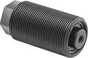 |  |
Small yet powerful, these cylinders thread into a system for workholding applications. Hydraulic pressure extends the piston rod and an internal spring retracts it. UN/UNF (SAE Straight) thread connections have straight threads and are also known as O-ring Boss fittings.
Body | Rod | Inlet/Outlet Connection | |||||||||||||||||
|---|---|---|---|---|---|---|---|---|---|---|---|---|---|---|---|---|---|---|---|
Stroke Lg. | Thread Size | Lg. | Max. Push Force, lbf | Retracted Lg. | Extended Lg. | Thread Size | Thread Dp. | Dia. | Overall Dia. | Thread Size | Dash Size | Thread Type | Body Material | Max. Pressure, psi | Cylinder Cushion Type | Each | |||
1" Diameter Bore | |||||||||||||||||||
| 1/2" | 1 5/16"-16 | 2 1/4" | 3,920 | 2 3/4" | 3 1/4" | 1/4"-20 | 3/4" | 5/8" | 1 5/16" | 7/16"-20 | 04 | UN/UNF (SAE Straight) | Steel | 5,000 | None | 6297K14 | 0000000 | ||
| 1" | 1 5/16"-16 | 3 1/4" | 3,920 | 3 3/4" | 4 3/4" | 1/4"-20 | 7/8" | 5/8" | 1 5/16" | 7/16"-20 | 04 | UN/UNF (SAE Straight) | Steel | 5,000 | None | 6297K15 | 000000 | ||
1 1/2" Diameter Bore | |||||||||||||||||||
| 1/2" | 1 7/8"-16 | 2 5/8" | 8,830 | 3 1/8" | 3 5/8" | 5/16"-18 | 7/8" | 1" | 1 7/8" | 7/16"-20 | 04 | UN/UNF (SAE Straight) | Steel | 5,000 | None | 6297K16 | 000000 | ||
| 1" | 1 7/8"-16 | 4 1/4" | 8,830 | 4 3/4" | 5 3/4" | 5/16"-18 | 7/8" | 1" | 1 7/8" | 7/16"-20 | 04 | UN/UNF (SAE Straight) | Steel | 5,000 | None | 6297K17 | 000000 | ||


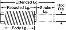
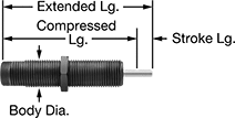
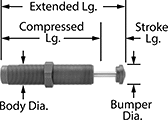
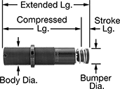
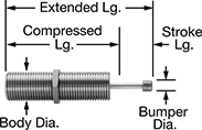
Self-Adjusting Shock Absorbers
Threaded-Body Mount
 |  |
No Bumper | Acetal Bumper |
 |  |
Aluminum Bumper | Urethane Rubber Bumper |
 |
Nylon Bumper |
 |
Steel Bumper |
Body | Rod | Bumper | ||||||||||||||
|---|---|---|---|---|---|---|---|---|---|---|---|---|---|---|---|---|
Energy Cap., in·lbf | Max. Cycles per min., cpm | Stroke Lg. | Extended Lg. | Compressed Lg. | Dia. | Thread Size | Material | Dia. | Material | Dia. | Material | Temp. Range, ° F | Each | |||
| 9 | 33 | 0.2" | 1.22" | 1.02" | 0.24" | M6 × 0.5 mm | Black-Oxide Steel | 0.08" | Stainless Steel | — | — | 32 to 150 | 3692K24 | 000000 | ||
| 11 | 53 | 0.2" | 1.52" | 1.32" | 0.31" | M8 × 0.75 mm | Black-Oxide Steel | 0.08" | Stainless Steel | 0.19" | Acetal | 32 to 150 | 3692K11 | 00000 | ||
| 11 | 53 | 0.2" | 1.52" | 1.32" | 0.31" | M8 × 1 mm | Black-Oxide Steel | 0.08" | Stainless Steel | 0.19" | Acetal | 32 to 150 | 3692K13 | 00000 | ||
| 17 | 70 | 0.24" | 1.97" | 1.73" | 0.31" | M8 × 1 mm | Black-Oxide Steel | 0.08" | Chrome-Plated Steel | 0.26" | Urethane Rubber | 14 to 176 | 6528K511 | 00000 | ||
| 20 | 167 | 0.26" | 2.27" | 2.01" | 0.375" | 3/8"-32 | Black-Oxide Steel | 0.13" | Stainless Steel | 0.3" | Steel | 32 to 150 | 3740K11 | 00000 | ||
| 20 | 167 | 0.26" | 2.27" | 2.01" | 0.39" | M10 × 1 mm | Black-Oxide Steel | 0.13" | Stainless Steel | 0.3" | Steel | 32 to 150 | 3692K15 | 00000 | ||
| 35 | 63 | 0.31" | 2.24" | 1.93" | 0.39" | M10 × 1 mm | Black-Oxide Steel | 0.1" | Chrome-Plated Steel | 0.34" | Urethane Rubber | 14 to 176 | 6528K512 | 00000 | ||
| 44 | 59 | 0.39" | 2.74" | 2.35" | 0.48" | M12 × 1 mm | Black-Oxide Steel | 0.12" | Chrome-Plated Steel | 0.41" | Urethane Rubber | 14 to 176 | 6528K513 | 00000 | ||
| 75 | 56 | 0.4" | 2.76" | 2.36" | 0.48" | M12 × 1 mm | Black-Oxide Steel | 0.13" | Stainless Steel | 0.3" | Steel | 32 to 150 | 3692K16 | 00000 | ||
| 75 | 56 | 0.4" | 2.76" | 2.36" | 0.5" | 1/2"-20 | Black-Oxide Steel | 0.13" | Stainless Steel | 0.3" | Steel | 32 to 150 | 3740K12 | 00000 | ||
| 100 | 10 | 0.25" | 2.75" | 2.5" | 0.55" | M14 × 1.5 mm | Black-Oxide Steel | 0.15" | Stainless Steel | 0.25" | Aluminum | -22 to 140 | 9530K66 | 000000 | ||
| 123 | 41 | 0.5" | 3.66" | 3.16" | 0.55" | M14 × 1 mm | Black-Oxide Steel | 0.19" | Stainless Steel | 0.47" | Nylon | 32 to 150 | 3692K27 | 000000 | ||
| 123 | 41 | 0.5" | 3.66" | 3.16" | 0.563" | 9/16"-18 | Black-Oxide Steel | 0.19" | Stainless Steel | 0.47" | Nylon | 32 to 150 | 3740K19 | 000000 | ||
| 142 | 31 | 0.39" | 3.62" | 3.22" | 0.48" | M12 × 1 mm | Black-Oxide Steel | 0.15" | Stainless Steel | — | — | 32 to 150 | 3740K421 | 000000 | ||
| 175 | 29 | 0.5" | 3.41" | 2.91" | 0.55" | M14 × 1.5 mm | Black-Oxide Steel | 0.19" | Stainless Steel | — | — | 32 to 150 | 3740K412 | 000000 | ||
| 175 | 34 | 0.5" | 3.41" | 2.91" | 0.55" | M14 × 1.5 mm | Black-Oxide Steel | 0.19" | Stainless Steel | — | — | 32 to 150 | 3740K411 | 000000 | ||
| 200 | 10 | 0.5" | 3.75" | 3.25" | 0.78" | M20 × 1.5 mm | Black-Oxide Steel | 0.15" | Stainless Steel | 0.25" | Aluminum | -22 to 140 | 9530K67 | 000000 | ||
| 225 | 22 | 0.63" | 4.5" | 3.87" | 0.55" | M14 × 1.5 mm | Black-Oxide Steel | 0.16" | Stainless Steel | 0.47" | Steel | 32 to 150 | 3692K19 | 00000 | ||
| 225 | 22 | 0.63" | 4.5" | 3.87" | 0.563" | 9/16"-18 | Black-Oxide Steel | 0.16" | Stainless Steel | 0.47" | Steel | 32 to 150 | 3740K15 | 000000 | ||
| 250 | 26 | 1" | 4.75" | 3.75" | 0.98" | M25 × 1.5 mm | Black-Oxide Steel | 0.19" | Stainless Steel | 0.38" | Aluminum | -22 to 140 | 9530K68 | 000000 | ||
| 274 | 27 | 0.47" | 3.7" | 3.22" | 0.55" | M14 × 1.5 mm | Black-Oxide Steel | 0.19" | Stainless Steel | — | — | 32 to 150 | 3740K415 | 000000 | ||
| 288 | 23 | 0.5" | 4.07" | 3.57" | 0.75" | 3/4"-16 | Black-Oxide Steel | 0.25" | Stainless Steel | 0.66" | Nylon | 32 to 150 | 3740K21 | 000000 | ||
| 288 | 23 | 0.5" | 4.07" | 3.57" | 0.78" | M20 × 1.5 mm | Black-Oxide Steel | 0.25" | Stainless Steel | 0.66" | Nylon | 32 to 150 | 3692K28 | 000000 | ||
| 300 | 22 | 0.75" | 4.62" | 3.87" | 0.75" | 3/4"-16 | Black-Oxide Steel | 0.19" | Stainless Steel | 0.66" | Steel | 32 to 150 | 3740K16 | 000000 | ||
| 300 | 22 | 0.75" | 4.62" | 3.87" | 0.78" | M20 × 1.5 mm | Black-Oxide Steel | 0.19" | Stainless Steel | 0.66" | Steel | 32 to 150 | 3692K21 | 00000 | ||
| 360 | 19 | 0.5" | 3.81" | 3.31" | 0.75" | 3/4"-16 | Black-Oxide Steel | 0.25" | Stainless Steel | — | — | 32 to 150 | 3740K413 | 000000 | ||
| 360 | 19 | 0.5" | 3.81" | 3.31" | 0.78" | M20 × 1.5 mm | Black-Oxide Steel | 0.25" | Stainless Steel | — | — | 32 to 150 | 3740K414 | 000000 | ||
| 600 | 17 | 1" | 5.76" | 4.76" | 0.98" | M25 × 1.5 mm | Black-Oxide Steel | 0.31" | Stainless Steel | 0.9" | Nylon | 32 to 150 | 3692K29 | 000000 | ||
| 600 | 17 | 1" | 5.76" | 4.76" | 1" | 1"-12 | Black-Oxide Steel | 0.31" | Stainless Steel | 0.9" | Nylon | 32 to 150 | 3740K22 | 000000 | ||
| 620 | 11 | 0.59" | 4.15" | 3.56" | 0.75" | 3/4"-16 | Black-Oxide Steel | 0.25" | Stainless Steel | 0.66" | Steel | 32 to 150 | 3740K1 | 000000 | ||
| 650 | 10 | 0.59" | 4.15" | 3.56" | 0.75" | 3/4"-16 | Black-Oxide Steel | 0.25" | Stainless Steel | 0.66" | Steel | 32 to 150 | 3740K418 | 000000 | ||
| 650 | 10 | 1" | 4.75" | 3.75" | 0.98" | M25 × 1.5 mm | Black-Oxide Steel | 0.19" | Stainless Steel | 0.38" | Aluminum | -22 to 140 | 9530K71 | 000000 | ||
| 650 | 15 | 1" | 5.62" | 4.62" | 0.98" | M25 × 1.5 mm | Black-Oxide Steel | 0.25" | Stainless Steel | 0.9" | Steel | 32 to 150 | 3692K23 | 000000 | ||
| 650 | 15 | 1" | 5.62" | 4.62" | 1" | 1"-12 | Black-Oxide Steel | 0.25" | Stainless Steel | 0.9" | Steel | 32 to 150 | 3740K18 | 000000 | ||
| 690 | 15 | 1" | 5.93" | 4.93" | 1.06" | M27 × 3 mm | Black-Oxide Steel | 0.31" | Chrome-Plated Steel | 0.89" | Urethane Rubber | 14 to 176 | 6528K514 | 000000 | ||
| 975 | 14 | 1.58" | 7.44" | 5.86" | 1" | 1"-12 | Black-Oxide Steel | 0.25" | Stainless Steel | 0.9" | Steel | 32 to 150 | 3740K3 | 000000 | ||
| 1,860 | 5 | 0.91" | 5.51" | 4.6" | 0.98" | M25 × 1.5 mm | Black-Oxide Steel | 0.38" | Stainless Steel | 0.9" | Steel | 32 to 150 | 3740K419 | 000000 | ||
| 1,860 | 5 | 0.91" | 5.51" | 4.6" | 1" | 1"-12 | Black-Oxide Steel | 0.38" | Stainless Steel | 0.9" | Steel | 32 to 150 | 3740K2 | 000000 | ||
| 2,000 | 10 | 1" | 5.25" | 4.25" | 1.3" | M33 × 1.5 mm | Black-Oxide Steel | 0.28" | Stainless Steel | 0.5" | Aluminum | -22 to 140 | 9530K72 | 000000 | ||
| 5,000 | 10 | 2" | 8.25" | 6.25" | 1.375" | 1 3/8"-12 | Black-Oxide Steel | 0.34" | Stainless Steel | 0.63" | Aluminum | -22 to 140 | 9530K54 | 000000 | ||
| 5,000 | 10 | 2" | 8.25" | 6.25" | 1.42" | M36 × 1.5 mm | Black-Oxide Steel | 0.34" | Stainless Steel | 0.63" | Aluminum | -22 to 140 | 9530K74 | 000000 | ||
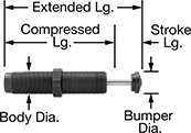
Adjustable Shock Absorbers
Threaded-Body Mount
 |
Threaded-body mount shock absorbers use Mounting Blocks for Shock Absorbers (not included) for mounting. They include mounting nuts.
Nylon Bumper—Nylon bumpers are nonmarring.
Urethane Rubber Bumper—Urethane rubber bumpers are nonmarring.
Body | Rod | Bumper | ||||||||||||||
|---|---|---|---|---|---|---|---|---|---|---|---|---|---|---|---|---|
Energy Cap., in·lbf | Max. Cycles per min., cpm | Stroke Lg. | Extended Lg. | Compressed Lg. | Dia. | Thread Size | Material | Dia. | Material | Dia. | Material | Temp. Range, ° F | Each | |||
Variable Adjustment | ||||||||||||||||
| 35 | 25 | 0.4" | 3.31" | 2.91" | 0.42" | M12 × 1 mm | Black-Oxide Steel | 0.13" | Stainless Steel | 0.3" | Steel | 32 to 150 | 3691K11 | 000000 | ||
| 35 | 25 | 0.4" | 3.31" | 2.91" | 0.5" | 1/2"-20 | Black-Oxide Steel | 0.13" | Stainless Steel | 0.3" | Steel | 32 to 150 | 3742K11 | 00000 | ||
| 200 | 25 | 0.5" | 3.67" | 3.17" | 0.46" | M14 × 1.5 mm | Black-Oxide Steel | 0.19" | Stainless Steel | 0.47" | Nylon | 32 to 150 | 3691K12 | 000000 | ||
| 200 | 25 | 0.5" | 3.67" | 3.17" | 0.563" | 9/16"-18 | Black-Oxide Steel | 0.19" | Stainless Steel | 0.47" | Nylon | 32 to 150 | 3742K12 | 000000 | ||
| 275 | 18 | 0.5" | 4.35" | 3.85" | 0.75" | 3/4"-16 | Anodized Aluminum | 0.19" | Nickel-Plated Steel | 0.5" | Urethane Rubber | 32 to 150 | 3742K27 | 000000 | ||
| 275 | 18 | 0.5" | 4.35" | 3.85" | 0.75" | M20 × 1.5 mm | Anodized Aluminum | 0.19" | Nickel-Plated Steel | 0.5" | Urethane Rubber | 32 to 150 | 3691K24 | 000000 | ||
| 300 | 22 | 0.75" | 4.67" | 3.92" | 0.75" | 3/4"-16 | Black-Oxide Steel | 0.19" | Stainless Steel | 0.66" | Steel | 32 to 150 | 3742K19 | 000000 | ||
| 300 | 22 | 0.75" | 4.67" | 3.92" | 0.75" | M20 × 1.5 mm | Black-Oxide Steel | 0.19" | Stainless Steel | 0.66" | Steel | 32 to 150 | 3691K21 | 000000 | ||
| 600 | 17 | 1" | 5.6" | 4.6" | 1" | 1"-12 | Black-Oxide Steel | 0.25" | Stainless Steel | 0.9" | Steel | 32 to 150 | 3742K21 | 000000 | ||
| 600 | 17 | 1" | 5.62" | 4.62" | 1" | M25 × 1.5 mm | Black-Oxide Steel | 0.25" | Stainless Steel | 0.9" | Steel | 32 to 150 | 3691K22 | 000000 | ||
| 715 | 15 | 1" | 5.62" | 4.62" | 1" | 1"-12 | Anodized Aluminum | 0.25" | Chrome-Plated Steel | 0.62" | Urethane Rubber | 32 to 150 | 3742K28 | 000000 | ||
| 715 | 15 | 1" | 5.62" | 4.62" | 1" | M27 × 3 mm | Anodized Aluminum | 0.25" | Chrome-Plated Steel | 0.62" | Urethane Rubber | 32 to 150 | 3691K25 | 000000 | ||
| 1,500 | 7 | 0.91" | 5.44" | 4.53" | 1.15" | M33 × 1.5 mm | Black-Oxide Steel | 0.375" | Chrome-Plated Steel | 1" | Steel | 32 to 150 | 3691K15 | 000000 | ||
| 1,500 | 7 | 0.91" | 5.44" | 4.53" | 1.25" | 1 1/4"-12 | Black-Oxide Steel | 0.375" | Chrome-Plated Steel | 1" | Steel | 32 to 150 | 3742K15 | 000000 | ||
| 3,450 | 5 | 0.91" | 5.69" | 4.78" | 1.65" | M45 × 1.5 mm | Black-Oxide Steel | 0.5" | Chrome-Plated Steel | 1.38" | Steel | 32 to 150 | 3691K16 | 000000 | ||
| 3,450 | 5 | 0.91" | 5.69" | 4.78" | 1.75" | 1 3/4"-12 | Black-Oxide Steel | 0.5" | Chrome-Plated Steel | 1.38" | Steel | 32 to 150 | 3742K16 | 000000 | ||
| 6,900 | 2 | 1.91" | 7.69" | 5.78" | 1.65" | M45 × 1.5 mm | Black-Oxide Steel | 0.5" | Chrome-Plated Steel | 1.38" | Steel | 32 to 150 | 3691K17 | 000000 | ||
| 6,900 | 2 | 1.91" | 7.69" | 5.78" | 1.75" | 1 3/4"-12 | Black-Oxide Steel | 0.5" | Chrome-Plated Steel | 1.38" | Steel | 32 to 150 | 3742K17 | 000000 | ||
| 10,350 | 2 | 2.91" | 9.69" | 6.78" | 1.75" | 1 3/4"-12 | Black-Oxide Steel | 0.5" | Chrome-Plated Steel | 1.38" | Steel | 32 to 150 | 3742K18 | 000000 | ||
| 11,506 | 2 | 2.91" | 9.69" | 6.78" | 1.75" | M45 × 1.5 mm | Black-Oxide Steel | 0.5" | Chrome-Plated Steel | 1.38" | Steel | 32 to 150 | 3691K23 | 000000 | ||
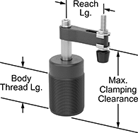
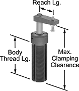
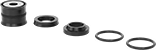
Threaded Air-Powered Hold-Down Fixture Clamps for Welding
 |  |
Rubber Holding Screw Tip | Steel Holding Screw Tip |
 | |
Extended Clamping Arm | Clamping Arm Adapter |
Screw these clamps directly into a tapped hole and use air pressure to quickly and consistently clamp and release parts when welding. Compact and lightweight, these clamps are easy to move and reposition when welding. They’re also known as swing clamps. Connect these clamps to a control valve and air line. When pressure is applied, the arm on these clamps rotates 90° into position over your workpiece before clamping down. When pressure is released, the arm rises and rotates out of the way, so you can load or unload parts.
Sensor Ready—Sensor-ready clamps activate relays and controllers when used with a sensor (not included).
Rubber Holding Screw Tip—Clamps with a rubber-tipped holding screw are nonmarring. Their tip is removable.
Replacement Arms—Replacement arms (sold separately) do not include a holding screw. Extended arms (sold separately) give your clamp a longer reach than standard arms. However, you’ll have to use lower pressure, which means the actual clamping force will be lower than the clamp’s listed rating.
Arm Adapters—Add an arm adapter to mount your own custom-machined arm.
Clamps | Replacement Arms | Extended Arms | Arm Adapters | ||||||||||||||||||||||
|---|---|---|---|---|---|---|---|---|---|---|---|---|---|---|---|---|---|---|---|---|---|---|---|---|---|
Body | Holding Screw | Female Air Inlet and Outlet | |||||||||||||||||||||||
Max. Clamping Clearance | Vert. Travel During Rotation | Max. Clamping Stroke | Holding Cap., lb. | Reach Lg. | Thread Size | Thread Lg. | Sensor Ready | Overall Ht. | Thread Size | Tip Material | Pipe Size | Thread Size | Thread Type | Material | Each | Each | Lg. | Each | Each | ||||||
90° Clockwise Rotation | |||||||||||||||||||||||||
| 4" | 1 3/32" | 17/32" | 35 | 1 15/16" | M40 × 1.5 mm | 1 11/16" | Not Sensor Ready | 4 5/8" | M6 × 1 mm | Rubber | — | M5 × 0.8 mm | Metric | Aluminum | 9986N11 | 0000000 | 9986N17 | 000000 | — | ——— | 0 | 9986N18 | 000000 | ||
| 4 3/8" | 15/32" | 3/8" | 35 | 1 1/8" | 1 1/8"-16 | 2 7/8" | Sensor Ready | 4 3/4" | 10-32 | Steel | — | 10-32 | UNF | Aluminum | 50185A18 | 000000 | 50185A109 | 00000 | 2 7/8" | 50185A111 | 000000 | 50185A114 | 00000 | ||
| 4 9/16" | 1 1/8" | 17/32" | 100 | 2 9/16" | M55 × 1.5 mm | 2 1/4" | Not Sensor Ready | 5 1/4" | M8 × 1.25 mm | Rubber | 1/8 | — | BSPP | Aluminum | 9986N12 | 000000 | 50185A106 | 00000 | — | ——— | 0 | 50185A108 | 00000 | ||
| 5 5/16" | 3/4" | 1/2" | 95 | 1 5/8" | 1 3/4"-12 | 3 1/4" | Sensor Ready | 6 1/8" | 3/8"-16 | Rubber | 1/8 | — | NPT | Aluminum | 50185A15 | 000000 | 50185A112 | 00000 | — | ——— | 0 | ——— | 0 | ||
90° Counterclockwise Rotation | |||||||||||||||||||||||||
| 4" | 1 3/32" | 17/32" | 35 | 1 15/16" | M40 × 1.5 mm | 1 11/16" | Not Sensor Ready | 4 5/8" | M6 × 1 mm | Rubber | — | M5 × 0.8 mm | Metric | Aluminum | 9986N13 | 000000 | 9986N17 | 00000 | — | ——— | 0 | 9986N18 | 00000 | ||
| 4 3/8" | 15/32" | 3/8" | 35 | 1 1/8" | 1 1/8"-16 | 2 7/8" | Sensor Ready | 4 3/4" | 10-32 | Steel | — | 10-32 | UNF | Aluminum | 50185A19 | 000000 | 50185A109 | 00000 | 2 7/8" | 50185A111 | 00000 | 50185A114 | 00000 | ||
| 4 9/16" | 1 1/8" | 17/32" | 100 | 2 9/16" | M55 × 1.5 mm | 2 1/4" | Not Sensor Ready | 5 1/4" | M8 × 1.25 mm | Rubber | 1/8 | — | BSPP | Aluminum | 9986N14 | 000000 | 50185A106 | 00000 | — | ——— | 0 | 50185A108 | 00000 | ||
| 5 5/16" | 3/4" | 1/2" | 95 | 1 5/8" | 1 3/4"-12 | 3 1/4" | Sensor Ready | 6 1/8" | 3/8"-16 | Rubber | 1/8 | — | NPT | Aluminum | 50185A16 | 000000 | 50185A112 | 00000 | — | ——— | 0 | ——— | 0 | ||
 |
For Max. Clamping Clearance | Includes | Each | ||
|---|---|---|---|---|
| 4 3/8" | Rod Seal, Rod Wiper, End Cap Seal, Retaining Ring, Aluminum Piston with a Molded Seal and Groove with a Magnetic Ring | 50185A116 | 000000 | |
| 5 5/16" | Rod Seal, Rod Wiper, End Cap Seal, Retaining Ring, Aluminum Piston with a Molded Seal and Groove with a Magnetic Ring | 9986N19 | 000000 |
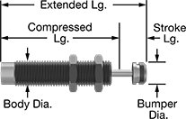
Corrosion-Resistant Self-Adjusting Shock Absorbers
Threaded-Body Mount
 |
Body | Rod | Bumper | ||||||||||||||
|---|---|---|---|---|---|---|---|---|---|---|---|---|---|---|---|---|
Energy Cap., in·lbf | Max. Cycles per min., cpm | Stroke Lg. | Extended Lg. | Compressed Lg. | Dia. | Thread Size | Material | Dia. | Material | Dia. | Material | Temp. Range, ° F | Each | |||
| 100 | 10 | 0.25" | 2.75" | 2.5" | 0.56" | 9/16"-18 | Stainless Steel | 0.15" | Stainless Steel | 0.25" | Stainless Steel | -20 to 140 | 9553K1 | 0000000 | ||
| 200 | 10 | 0.5" | 3.75" | 3.25" | 0.75" | 3/4"-16 | Stainless Steel | 0.15" | Stainless Steel | 0.25" | Stainless Steel | -20 to 140 | 9553K2 | 000000 | ||
| 250 | 27 | 1" | 4.75" | 3.75" | 1" | 1"-12 | Stainless Steel | 0.19" | Stainless Steel | 0.38" | Stainless Steel | -20 to 140 | 9553K3 | 000000 | ||
| 650 | 10 | 1" | 4.75" | 3.75" | 1" | 1"-12 | Stainless Steel | 0.19" | Stainless Steel | 0.38" | Stainless Steel | -20 to 140 | 9553K4 | 000000 | ||
| 2,000 | 10 | 1" | 5.25" | 4.25" | 1.25" | 1 1/4"-12 | Stainless Steel | 0.28" | Stainless Steel | 0.5" | Stainless Steel | -20 to 140 | 9553K5 | 000000 | ||
| 5,000 | 10 | 2" | 8.25" | 6.25" | 1.38" | 1 3/8"-12 | Stainless Steel | 0.34" | Stainless Steel | 0.63" | Stainless Steel | -20 to 140 | 9553K7 | 000000 | ||
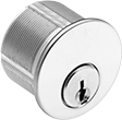
Pry-Resistant Keyed-Alike Lock Cylinders for Mortise-Mount Locks
 |  |  |
Schlage C Keyway | Yale Y8 Keyway | |||||||||
|---|---|---|---|---|---|---|---|---|---|---|
Cylinder Lg. | Keying | No. of Keys Included | Material | Choose a Finish | Each | Each | ||||
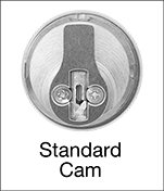
Standard Cam | ||||||||||
| 15/16" | Keyed Alike | 2 | Brass | Dull Chrome Plated, Polished Brass Plated | 1301A2 | 000000 | ——— | 0 | ||
| 1 1/8" | Keyed Alike | 2 | Brass | Dull Chrome Plated, Polished Brass Plated | 1301A26 | 00000 | 1301A42 | 000000 | ||
| 1 1/4" | Keyed Alike | 2 | Brass | Dull Chrome Plated, Polished Brass Plated | 1301A54 | 00000 | ——— | 0 | ||
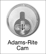
Adams-Rite Cam | ||||||||||
| 15/16" | Keyed Alike | 2 | Brass | Dull Chrome Plated, Polished Brass Plated | 1301A12 | 00000 | 1301A16 | 00000 | ||
Pry-Resistant Lock Cylinders for Mortise-Mount Locks
| | |
Schlage C Keyway | Yale Y8 Keyway | |||||||||
|---|---|---|---|---|---|---|---|---|---|---|
Cylinder Lg. | Keying | No. of Keys Included | Material | Choose a Finish | Each | Each | ||||
Standard Cam | ||||||||||
| 15/16" | Keyed Differently | 2 | Brass | Dull Chrome Plated, Polished Brass Plated | 1301A1 | 000000 | ——— | 0 | ||
| 1 1/8" | Keyed Differently | 2 | Brass | Dull Chrome Plated, Polished Brass Plated | 1301A23 | 00000 | 1301A27 | 000000 | ||
| 1 1/4" | Keyed Differently | 2 | Brass | Dull Chrome Plated, Polished Brass Plated | 1301A41 | 00000 | ——— | 0 | ||
Adams-Rite Cam | ||||||||||
| 15/16" | Keyed Differently | 2 | Brass | Dull Chrome Plated, Polished Brass Plated | 1301A11 | 00000 | 1301A15 | 00000 | ||
