


Matching Flow Diagrams to Replace an Air Directional Control Valve
More
Choosing an Air Directional Control Valve
More
Two-Hand Safety Switches
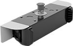
It takes two hands to activate these switches, minimizing the risk of accidental equipment start-up. They have an emergency stop push-button to immediately cut power. They’re rated IP65 for protection from low-pressure washdowns.
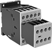
Switches with push-button actuators require a safety relay (sold separately) for a complete system.
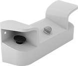
Switches with finger-touch actuators turn circuits on and off with a light touch, even when wearing gloves. An infrared sensor detects the lightest finger contact, and an indicator lights up to confirm when they are activated. Because they don't require you to press down a button to operate, they meet ANSI B11.TR1 standards to reduce hand, wrist, and arm fatigue. You'll need a relay or controller to complete your system—upgrade to a controller if you plan to operate additional devices beyond your switch.
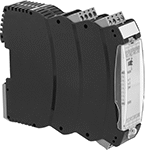
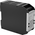
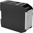
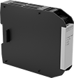
Safety controller expansion modules can be added to safety controllers to increase the number of inputs.
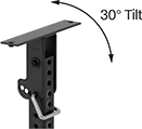
Telescoping stands can be added to switches with finger-touch actuators to mount them away from a wall. The stands telescope to adjust the height of the switch and tilt to adjust the angle of the switch.
Actuator | Mounting | ||||||||||||||
|---|---|---|---|---|---|---|---|---|---|---|---|---|---|---|---|
| No. of Circuits Controlled | Switch Starting Position | Switch Action | Industry Designation | Material | Color | Switching Current @ Voltage | Ht. | Wd. | Dp. | No. of Holes | Hole Dia. | Mounting Fasteners Included | Features | Each | |
Push-Button Actuators | |||||||||||||||
| 2 | 1 Off (Normally Open) and 1 On (Normally Closed) | Springs Back (Momentary) | DPST-1NO/1NC | Plastic | Black | 8 A @ 250 V AC, 5 A @ 24 V DC | 7 5/16" | 18 1/2" | 5 7/16" | 2 | 29/64" | No | Emergency Stop Button | 65945K71 | 0000000 |
Finger-Touch Actuators | |||||||||||||||
| 2 | 1 Off (Normally Open) and 1 On (Normally Closed) | Springs Back (Momentary) | DPST-1NO/1NC | Plastic | Black | 0.15 A @ 24 V DC | 3 7/16" | 18 11/16" | 5 1/2" | 4 | 5/16" | No | Emergency Stop Button, Output Indicator, Power Indicator | 65945K41 | 000000 |
| Input Voltage | No. of Terminals | Switching Current @ Voltage | For DIN Rail Ht., mm | Wire Connection Type | Features | Each | |
2 Circuits Contolled with 1 Off (Normally Open) and 1 On (Normally Closed)—DPST-1NO/1NC | |||||||
|---|---|---|---|---|---|---|---|
| 24V DC | 12 | 5.5 A @ 24 V DC | 35 | Screw Terminals | Self-Monitoring Circuitry | 65945K72 | 0000000 |
hp @ Switching Voltage | |||||||||||||
|---|---|---|---|---|---|---|---|---|---|---|---|---|---|
| Input Voltage | No. of Terminals | Switching Current @ Voltage | Max. Switching Voltage | Single Phase | Three Phase | Auxiliary Contact Switch Starting Position (No. of Contacts) | For DIN Rail Size, mm | Wire Connection Type | Features | Max. System Safety Rating | Auxiliary Contact Switch Starting Position | Each | |
3 3 Off (Normally Open)—3PST-NO | |||||||||||||
| 24V DC | 18 | 9 A @ 400 V AC | 600V AC | 1/2 hp @ 120 V AC 1 1/2 hp @ 240 V AC | 3 hp @ 240 V AC 5 hp @ 480 V AC 7 1/2 hp @ 600 V AC | 1 Off (Normally Open) (2) 1 On (Normally Closed) (3) | 35 | Screw Terminals | Inspection Window, Interlocked Opposing Contacts, Mirror Auxiliary Contacts, Nondetachable Auxiliary Contacts, Recessed Terminals, Self-Monitoring Circuitry | PLe, SIL3, CAT 4, 600V | 2 Off (Normally Open) and 3 On (Normally Closed) | 6242N16 | 0000000 |

USB Connection | Ethernet Connection | ||||||||||||||
|---|---|---|---|---|---|---|---|---|---|---|---|---|---|---|---|
| No. of Inputs | Input Voltage | Signal Output Type | Type | Standard | Gender | Type | Gender | Communication Protocol | For Max. No. of Expansion Modules | Ht. | Wd. | Dp. | Display Type | Each | |
USB Connection | |||||||||||||||
| 26 | 24V DC | PNP | Micro B | 2.0 | Female | __ | __ | __ | 8 | 4 5/16" | 1 3/4" | 5 1/16" | LCD | 65945K46 | 000000000 |
USB and Ethernet Connection | |||||||||||||||
| 26 | 24V DC | PNP | Micro B | 2.0 | Female | RJ45 | Female | Ethernet/IP, Modbus TCP, Profinet | 8 | 4 5/16" | 1 3/4" | 5 1/16" | __ | 65945K47 | 00000000 |
| Input Voltage | No. of Outputs | Signal Output Type | Ht. | Wd. | Dp. | Each | |
| 24V DC | 4 | PNP | 4 5/16" | 1" | 5 1/16" | 65945K48 | 0000000 |
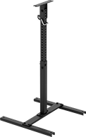
Base Mounting Holes | Head Mounting Holes | |||||||||||
|---|---|---|---|---|---|---|---|---|---|---|---|---|
| Ht. | Wd. | Dp. | Head Movement | Tilt Range of Motion | Material | No. of | Dia. | No. of | Dia. | Mounting Fasteners Included | Each | |
| 31 1/2"-48 1/2" | 24 1/16" | 24" | Tilt | 30° | Steel | 4 | 29/64" | 2 | 5/16" | Yes | 65945K44 | 0000000 |
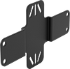
Mounting | ||||||||
|---|---|---|---|---|---|---|---|---|
| Ht. | Wd. | Dp. | Material | No. of Holes | Hole Dia. | Mounting Fasteners Included | Each | |
| 5 15/16" | 10 1/4" | 3/8" | Steel | 4 | 3/8" | Yes | 65945K45 | 000000 |

Wire Leads | |||||||||||
|---|---|---|---|---|---|---|---|---|---|---|---|
| Input Voltage | Signal Output Type | Ht. | Wd. | Dp. | Thread Size | Cable Lg., ft. | No. of | Lg., ft. | Features | Each | |
| 10V DC-30V DC | PNP | 2 5/16" | 2 3/8" | 1 11/16" | M30 × 1.5 mm | 1 | 4 | 1 | Output Indicator, Power Indicator | 65945K43 | 0000000 |
Dual-Operator Safety Switches
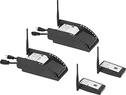
To prevent accidents, these switches won’t let your machine start running unless two people in different locations coordinate control. This is useful for large operations where it would be difficult to hear or see someone call for power to be cut. They come with two foot switches that communicate wirelessly—both need to be pressed at the same time for your machine to run. For example, if used with a machine that pulls wire up a building through conduit, this means that two people dozens of floors apart can each stop the machine by releasing their foot. As an extra precaution, give the included pendant switches to people walking around your operation. If they see a problem, the pendant switches shut power off with a push of a button, even if the foot switches are pressed.
The foot switches work up to 3.7 miles away from each other if there’s a clear line of sight between the two. If there are walls or other obstacles, they work up to 1,500 ft. away from each other. Plug your equipment into the receiver foot switch before plugging the switch into an outlet—no wiring is required.
| No. of Circuits Controlled | Switch Starting Position | Switch Action | Industry Designation | Switching Current @ Voltage | Max. Transmission Distance, mi | Ht. | Wd. | Dp. | Environmental Rating | Includes | Each | |
Aluminum Housing with Amperage Draw Gauge and LED Status Indicator | ||||||||||||
|---|---|---|---|---|---|---|---|---|---|---|---|---|
NEMA 5-20 Plug × NEMA 5-20 Socket | ||||||||||||
| 1 | 1 Off (Normally Open) | Springs Back (Momentary) | SPST-NO | 20 A @ 120 V AC | 3.7 | 4 1/4" | 6 1/4" | 12 1/4" | IP55 | Receiver Foot Switch, Transmitter Foot Switch, Two Wireless Pendant Switches, Carrying Case, NEMA 5-15 Plug Adapter, Turn-Lock Plug Adapter, Two Battery Chargers | 6599N11 | 000000000 |
Remote-Location Two-Hand Single-Action Air Directional Control Valves
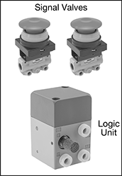
The push buttons that operate these valves are separate from the logic unit, allowing you to position them away from machinery. Since both hands are required to simultaneously press the buttons, they protect workers from accidental machinery start-up. Also known as 3-way and 3/2 valves, they create one action, such as extending a cylinder. Valves direct airflow from the inlet to your equipment and exhaust return airflow to create motion. They're normally closed to block airflow until actuated. Return actuation is by spring, so valves return to their starting position as soon as you release the actuator. In the off position, they exhaust air from the system, allowing equipment to reset so the action can be repeated.
Note: Valve is sold as a complete unit, consisting of one logic unit and two signal valves. Port size given is for the logic unit. Signal valve port size is 1/8 NPT female.
Flow coefficient (Cv) is a measurement that indicates how much airflow can pass through a valve.
Overall | ||||||||||||||
|---|---|---|---|---|---|---|---|---|---|---|---|---|---|---|
| No. of Flow Ports | For Inlet Tube OD | For Outlet Tube OD | Exhaust Connection Type | Max. Flow Rate, scfm @ 100 psi | Flow Coefficient (Cv) | Pressure Range, psi | Vacuum Rating | Lg. | Wd. | Ht. | For Panel Cutout Dia. | Mounting Fasteners Included | Each | |
Push-to-Connect Female Inlet × Push-to-Connect Female Outlet | ||||||||||||||
| 3 | 1/4" | 1/4" | Push to Connect | 3.8 | 0.11 | 36-145 | Not Rated | 2 1/2" | 1 3/4" | 2 3/4" | 1 1/8" | No | 6282K55 | 0000000 |
Two-Hand Single-Action Air Directional Control Valves
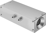
Since both hands are required to simultaneously press the buttons, these valves protect workers from accidental machinery start-up. Also known as 2-hand control valves, they create one action, such as extending a cylinder. Valves direct airflow from the inlet to your equipment and exhaust return airflow to create motion. They can be installed normally open to allow airflow until actuated, or installed to block airflow until actuated. Return actuation is by spring, so valves return to their starting position as soon as you release the actuator. These valves actuate any 3 or 4-way air piloted spring return power valve or small single-acting cylinders. In the off position, they exhaust air pressure from the system to the atmosphere, allowing equipment to reset so the action can be repeated.
Flow coefficient (Cv) is a measurement that indicates how much airflow can pass through a valve.
Overall | |||||||||||||
|---|---|---|---|---|---|---|---|---|---|---|---|---|---|
| Actuation Force, oz. | No. of Flow Ports | Inlet Size | Outlet Size | Max. Flow Rate, scfm @ 100 psi | Flow Coefficient (Cv) | Pressure Range, psi | Vacuum Rating | Lg. | Wd. | Ht. | Mounting Fasteners Included | Each | |
Threaded Female Inlet × Threaded Female Outlet | |||||||||||||
| 6 | 2 | 1/8 NPT | 1/8 NPT | 6 | 0.11 | 70-100 | Not Rated | 10 1/2" | 3 1/2" | 3 3/16" | No | 62115K22 | 000000000 |
| 18 | 2 | 1/8 NPT | 1/8 NPT | 6 | 0.11 | 70-100 | Not Rated | 10 1/2" | 3 1/2" | 3 3/16" | No | 62115K21 | 00000000 |
Two-Hand Two-Action Air Directional Control Valves
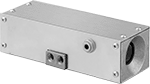
Since both hands are required to simultaneously press the buttons, these valves protect workers from accidental machinery start-up. Also known as 4-way and 4/2 valves, they create two actions, such as extending and then retracting a double-acting cylinder. They direct airflow from the inlet to your equipment and exhaust return airflow to create motion. Return actuation is by spring, so valves return to their original position as soon as you release the actuator.
Flow coefficient (Cv) is a measurement that indicates how much airflow can pass through a valve.
Overall | ||||||||||||||||
|---|---|---|---|---|---|---|---|---|---|---|---|---|---|---|---|---|
| Actuation Force, oz. | No. of Flow Ports | Inlet Size | For Inlet Tube OD | Outlet Size | For Outlet Tube OD | Exhaust Connection Type | Max. Flow Rate, scfm @ 100 psi | Flow Coefficient (Cv) | Pressure Range, psi | Vacuum Rating | Lg. | Wd. | Ht. | Mounting Fasteners Included | Each | |
Threaded Female Inlet × Threaded Female Outlet | ||||||||||||||||
| 6 | 4 | 1/4 NPTF | 1/4" | 1/4 NPTF | 1/4" | Threaded | 56 | 1 | 70-100 | Not Rated | 10 1/2" | 3 1/2" | 3 3/16" | No | 62115K24 | 000000000 |
| 18 | 4 | 1/4 NPTF | 1/4" | 1/4 NPTF | 1/4" | Threaded | 56 | 1 | 70-100 | Not Rated | 10 1/2" | 3 1/2" | 3 3/16" | No | 62115K23 | 00000000 |
Dual-Input Air Directional Control Valves

Air pressure must be supplied to both inlets before the output port will open, allowing airflow to your equipment. When the two input flows have different pressure levels, the output airflow will always be the lower of the two input pressures. Also known as "and" valves.
Flow coefficient (Cv) is a measurement that indicates how much airflow can pass through a valve.
Overall | ||||||||||||||
|---|---|---|---|---|---|---|---|---|---|---|---|---|---|---|
| No. of Flow Ports | Inlet Size | Outlet Size | Max. Flow Rate, scfm @ 100 psi | Flow Coefficient (Cv) | Pressure Range, psi | Vacuum Rating | Lg. | Wd. | Ht. | Mount Type | Mounting Fasteners Included | Mounting Hole Dia. | Each | |
Threaded Female Inlet × Threaded Female Outlet | ||||||||||||||
| 3 | 1/8 BSPP | 1/8 BSPP | 7.34 | 0.13 | 15-145 | Not Rated | 1 9/16" | 5/8" | 1 1/4" | Screw In | No | 0.18" | 3084N131 | 000000 |