Connection Style Connection Style |
---|
![]() | ![]() |
Threaded | Push to Connect |
![]() | ![]() |
Flanged | Barbed |
![]() | |
Yor-Lok |
For Use With For Use With | Show |
---|
|
For Use With For Use With | Hide |
---|
Body Material Body Material |
---|
|
System of Measurement System of Measurement |
---|
|
Valve Function Valve Function |
---|
|
Ball Material Ball Material |
---|
|
Maximum Pressure Maximum Pressure |
---|
Handle Type Handle Type |
---|
|
Minimum Temperature Minimum Temperature |
---|
|
Maximum Temperature Maximum Temperature |
---|
|
Flow Coefficient (Cv) Flow Coefficient (Cv) |
---|
End-to-End Length End-to-End Length |
---|
|
|
|
Actuation Actuation |
---|
|
More
More
More
More
The most chemical-resistant threaded valves we offer, these have a PTFE seal and an alloy body that can withstand extremely aggressive and corrosive chemicals, such as methyl ethyl ketone and toluene. They are standard port, so they slightly restrict flow.
Monel valves are more corrosion resistant than Alloy 20 valves.
Flow coefficient (Cv) is the amount of water (in gallons per minute) at 60° F that will flow through a fully open valve with a difference of 1 psi between the inlet and the outlet.
For technical drawings and 3-D models, click on a part number.
To withstand aggressive and corrosive solutions in miniature chemical-processing pipelines, these tiny valves have a chemical-resistant fluoroelastomer seal and a corrosion-resistant 303 stainless steel body. They are standard port, so they slightly restrict flow.
Flow coefficient (Cv) is the amount of water (in gallons per minute) at 60° F that will flow through a fully open valve with a difference of 1 psi between the inlet and the outlet.
For technical drawings and 3-D models, click on a part number.
Thread Size | Flow Coefficient (Cv) | Max. Pressure | Temperature Range, °F | Vacuum Rating, in. of Hg | End-to-End Lg. | Each | |
303 Stainless Steel Body | |||||||
---|---|---|---|---|---|---|---|
UNF Female × UNF Female | |||||||
10-32 | 0.1 | 250 psi @ 150° F | 0° to 400° | 25 | 11/16" | 0000000 | 0000000 |
Attach gauges or sensors to these valves so you can remove them for maintenance and calibration without depressurizing your line. Also known as block and bleed valves, turn the handles to block both upstream and downstream flow, drain the liquid trapped in the valve through the bleed port, and then remove your instrument from the gauge port. Often used in chemical-processing lines, these valves have a PEEK seal and a corrosion-resistant 316 stainless steel body. All are standard port, so they slightly restrict flow.
Flow coefficient (Cv) is the amount of water (in gallons per minute) at 60° F that will flow through a fully open valve with a difference of 1 psi between the inlet and the outlet.
Gauge Port | ||||||||
---|---|---|---|---|---|---|---|---|
Pipe Size | Pipe Size | Gender | Thread Type | Flow Coefficient (Cv) | Max. Pressure | Temperature Range, °F | Each | |
316 Stainless Steel Body | ||||||||
NPT Female × NPT Female | ||||||||
1/2 | 1/4 | Female | NPT | 6.4 | 10000 psi @ 170° F | -65° to 450° | 0000000 | 0000000 |
Barbs grip onto tubing, providing a secure hold. To withstand aggressive and corrosive solutions in chemical-processing applications, these valves have a plastic body and a chemical-resistant seal.
Full-port valves do not restrict flow.
Flow coefficient (Cv) is the amount of water (in gallons per minute) at 60° F that will flow through a fully open valve with a difference of 1 psi between the inlet and the outlet.
For Tube | |||||||||
---|---|---|---|---|---|---|---|---|---|
Pipe Size | ID | OD | Flow Coefficient (Cv) | Max. Pressure | Temperature Range, °F | Port Type | End-to-End Lg. | Each | |
NPT Male × Barbed | |||||||||
1/4 | 1/4" | 3/8" | 0.6 | 125 psi @ 140° F | 35° to 140° | Full | 3 1/2" | 00000000 | 000000 |
1/4 | 3/8" | 1/2" | Not Rated | 125 psi @ 140° F | 35° to 140° | Full | 3 1/2" | 00000000 | 00000 |
1/4 | 1/2" | 3/4" | Not Rated | 125 psi @ 140° F | 35° to 140° | Full | 3 1/2" | 00000000 | 00000 |
Barbed × Barbed | |||||||||
__ | 1/4" | __ | 0.4 | 125 psi @ 140° F | 35° to 140° | Full | 3 1/2" | 00000000 | 00000 |
__ | 3/8" | __ | 1.5 | 125 psi @ 140° F | 35° to 140° | Full | 3 1/2" | 00000000 | 00000 |
__ | 1/2" | __ | 8.8 | 125 psi @ 140° F | 35° to 140° | Full | 3 1/2" | 00000000 | 00000 |
Bolt these valves to ANSI flanges. A glass-filled vinyl ester body and a PTFE seal withstand aggressive and corrosive solutions in chemical-processing applications. Fix the lockable lever handle in place using a padlock (not included) with a shackle diameter up to 5/16”. All are standard port, so they slightly restrict flow.
Flow coefficient (Cv) is the amount of water (in gallons per minute) at 60° F that will flow through a fully open valve with a difference of 1 psi between the inlet and the outlet.
Bolts | ||||||||||||||
---|---|---|---|---|---|---|---|---|---|---|---|---|---|---|
Pipe Size | Flange OD | Circle Dia. | No. of Holes | Hole Dia. | Hole Size | Included | Flow Coefficient (Cv) | Max. Pressure | Temperature Range, °F | Vacuum Rating, in. of Hg | End-to-End Lg. | For Max. Shackle Dia. | Each | |
Glass-Filled Vinyl Ester Body | ||||||||||||||
Flanged × Flanged | ||||||||||||||
1 | 4 1/4" | 3 1/8" | 4 | 5/8" | 0.62" | No | 45 | 250 psi @ 100° F | -50° to 215° | 29.9 | 5" | 5/16" | 0000000 | 0000000 |
2 | 6" | 4 3/4" | 4 | 3/4" | 0.75" | No | 165 | 250 psi @ 100° F | -50° to 215° | 29.9 | 7" | 5/16" | 0000000 | 000000 |
3 | 7 1/2" | 6" | 4 | 3/4" | 0.75" | No | 350 | 250 psi @ 100° F | -50° to 215° | 29.9 | 8" | 5/16" | 0000000 | 000000 |
Barbs grip onto tubing, providing a secure hold. To withstand aggressive and corrosive solutions in chemical-processing applications, these valves have a PTFE seal and a PVDF body. Turn the handle to adjust flow in small increments for metering, sampling, and other applications requiring fine flow control. Threads and a hex nut below the handle allow you to install these valves in instrument panels. They have a nut that can be tightened to compress the packing if it leaks.
For technical drawings and 3-D models, click on a part number.
Insert tubing into the fittings on these valves—no heat, solder, or flux required. With a fluoroelastomer seal and a PVDF body, they can withstand aggressive and corrosive solutions in chemical-processing applications. Turn the handle to adjust flow in small increments for metering, sampling, and other applications requiring fine flow control. Threads and a hex nut below the handle allow you to install these valves in instrument panels. They have a nut that can be tightened to compress the packing if it leaks.
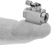
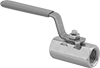
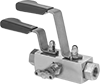
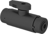
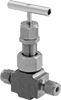
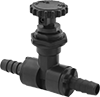
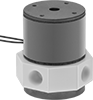
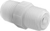
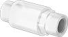
For extra gripping power and a strong seal, these valves have Yor-Lok fittings with two sleeves that bite into tubing as you tighten the nut. All are compatible with Swagelok®, Let-Lok, and Parker A-Lok fittings. The 316 stainless steel body and seal, the PTFE seat and packing, and the Monel needle can withstand aggressive and corrosive solutions in chemical-processing applications. Turn the handle to adjust flow in small increments for metering, sampling, and other applications requiring fine flow control. Threads and a hex nut below the handle allow you to mount these valves in instrument panels. All have a nut that can be tightened to compress the packing if it leaks. Valves have bubble-tight soft seats that provide a tight seal when the valve is completely closed.
Flow coefficient (Cv) is the amount of water (in gallons per minute) at 60° F that will flow through a fully open valve with a difference of 1 psi between the inlet and the outlet.
For Tube OD | Flow Coefficient (Cv) | Max. Pressure | Temperature Range, °F | Panel Cutout Dia. | End-to-End Lg. | Each | |
316 Stainless Steel Body | |||||||
---|---|---|---|---|---|---|---|
Yor Lok × Yor Lok | |||||||
1/4" | 0.56 | 7000 psi @ 400° F | -20° to 400° | 0.87" | 2 7/8" | 0000000 | 0000000 |
3/8" | 0.56 | 7000 psi @ 400° F | -20° to 400° | 0.87" | 2 7/8" | 0000000 | 000000 |
1/2" | 0.56 | 7000 psi @ 400° F | -20° to 400° | 0.87" | 3 1/8" | 0000000 | 000000 |
Often used for chemical analysis and other laboratory testing, these valves have a PTFE seal and body to withstand aggressive and corrosive solutions. All operate on electricity to automatically divert flow between ports. They do not require a pressure drop for operation. Any port can be used as an inlet or an outlet. Valves can direct flow from the inlet port to either outlet port. They cannot shut off flow. The actuator is mounted directly to the valve body to minimize movement and reduce wear.
Flow coefficient (Cv) is the amount of water (in gallons per minute) at 60° F that will flow through a fully open valve with a difference of 1 psi between the inlet and the outlet.
Mounting Holes | |||||||||||||||
---|---|---|---|---|---|---|---|---|---|---|---|---|---|---|---|
Pipe Size | Thread Size | Flow Pattern | Flow Coefficient (Cv) | Max. Pressure | Pressure Drop | Min. Pressure Drop Required | Temp. Range, °F | Actuation Time | Valve Lg. | O'all Ht. | Mounting Fasteners Included | No. of | Thread Size | Each | |
PTFE Plastic Body with Wire Leads—12V DC | |||||||||||||||
NPS Female × NPS Female × NPS Female | |||||||||||||||
1/8 | __ | L-Pattern | 15.85 | 30 psi @ 70° F | Zero Pressure Drop | None | 35° to 155° | 0.04 sec. | 1 3/4" | 2" | No | 7 | 4-40 | 0000000 | 0000000 |
UNF Female × UNF Female × UNF Female | |||||||||||||||
__ | 1/4"-28 | L-Pattern | 10.57 | 30 psi @ 70° F | Zero Pressure Drop | None | 35° to 155° | 0.02 sec. | 1 1/2" | 1 13/16" | No | 7 | 4-40 | 0000000 | 000000 |
__ | 10-32 | L-Pattern | 2.64 | 30 psi @ 70° F | Zero Pressure Drop | None | 35° to 155° | 0.02 sec. | 3/4" | 1 3/16" | No | 5 | 2-56 | 0000000 | 00000 |
PTFE Plastic Body with Wire Leads—24V DC | |||||||||||||||
NPS Female × NPS Female × NPS Female | |||||||||||||||
1/8 | __ | L-Pattern | 15.85 | 30 psi @ 70° F | Zero Pressure Drop | None | 35° to 155° | 0.04 sec. | 1 3/4" | 2" | No | 7 | 4-40 | 0000000 | 000000 |
UNF Female × UNF Female × UNF Female | |||||||||||||||
__ | 1/4"-28 | L-Pattern | 10.57 | 30 psi @ 70° F | Zero Pressure Drop | None | 35° to 155° | 0.02 sec. | 1 1/2" | 1 13/16" | No | 7 | 4-40 | 0000000 | 000000 |
__ | 10-32 | L-Pattern | 2.64 | 30 psi @ 70° F | Zero Pressure Drop | None | 35° to 155° | 0.02 sec. | 3/4" | 1 3/16" | No | 5 | 2-56 | 0000000 | 00000 |
These valves open to allow flow in one direction and close when flow stops or reverses.
Flow coefficient (Cv) is the amount of water (in gallons per minute) at 60° F that will flow through a fully open valve with a difference of 1 psi between the inlet and the outlet.
For technical drawings and 3-D models, click on a part number.
Pipe Size | Flow Coefficient (Cv) | Max. Pressure | Min. Opening Pressure, psi | Temperature Range, °F | Color | End-to-End Lg. | Each | |
NPT Male × NPT Male | ||||||||
---|---|---|---|---|---|---|---|---|
1/8 | Not Rated | 220 psi @ 70° F | 2.5 | 40° to 180° | White | 1" | 00000000 | 000000 |
1/4 | Not Rated | 220 psi @ 70° F | 2.5 | 40° to 180° | White | 1 7/16" | 00000000 | 00000 |
3/8 | Not Rated | 220 psi @ 70° F | 2.5 | 40° to 180° | White | 1 1/2" | 00000000 | 00000 |
1/2 | Not Rated | 220 psi @ 70° F | 2.5 | 40° to 180° | White | 1 13/16" | 00000000 | 00000 |
The most chemical-resistant check valves in our offering, these have a PFA body to withstand methyl ethyl ketone, sodium hypochlorite, and other extremely harsh chemicals. They open to allow flow in one direction and close when flow stops or reverses.
Flow coefficient (Cv) is the amount of water (in gallons per minute) at 60° F that will flow through a fully open valve with a difference of 1 psi between the inlet and the outlet.
For technical drawings and 3-D models, click on a part number.
Connect your outlet tubing into the push-to-connect fittings—no heat, solder, or flux required. These valves have a PVDF body and a fluoroelastomer seal for excellent chemical resistance. They open to allow flow in one direction and close when flow stops or reverses.
For technical drawings and 3-D models, click on a part number.
Pipe Size | For Tube OD | Max. Pressure | Min. Opening Pressure, psi | Temperature Range, °F | Color | End-to-End Lg. | Each | |
PVDF Plastic Body | ||||||||
---|---|---|---|---|---|---|---|---|
NPTF Male Inlet × Push-to-Connect Outlet | ||||||||
1/4 | 3/8" | 300 psi @ 70° F | 0.5 | 0° to 250° | Black | 1 3/8" | 0000000 | 000000 |
1/4 | 3/8" | 300 psi @ 70° F | 1.5 | 0° to 250° | Black/Blue | 1 3/8" | 0000000 | 00000 |
1/4 | 3/8" | 300 psi @ 70° F | 3 | 0° to 250° | Black/Red | 1 3/8" | 0000000 | 00000 |
1/4 | 3/8" | 300 psi @ 70° F | 4 | 0° to 250° | Black/Green | 1 3/8" | 0000000 | 00000 |
Prevent backflow in chemical tubing lines. These valves have barbed fittings that grip onto tubing, providing a secure hold. The plastic body and fluoroelastomer seal provide excellent chemical resistance. Valves open to allow flow in one direction and close when flow stops or reverses.
Polypropylene valves are more corrosion resistant than nylon valves.
Nylon valves are more impact resistant than polypropylene valves.
Flow coefficient (Cv) is the amount of water (in gallons per minute) at 60° F that will flow through a fully open valve with a difference of 1 psi between the inlet and the outlet.
For technical drawings and 3-D models, click on a part number.
Bolt these valves to ANSI flanges. The glass-filled vinyl body and PTFE seal stand up to a wide range of harsh chemicals. Valves open to allow flow in one direction and close when flow stops or reverses.
Flow coefficient (Cv) is the amount of water (in gallons per minute) at 60° F that will flow through a fully open valve with a difference of 1 psi between the inlet and the outlet.
Pipe Size | Flow Coefficient (Cv) | Max. Pressure | Min. Opening Pressure, psi | Temperature Range, °F | Color | End-to-End Lg. | For Flange Class | Flange OD | Number of Bolt Holes | Bolt Hole Size | Bolt Circle Dia. | Bolts Included | Each | |
Glass-Filled Vinyl Plastic Body | ||||||||||||||
---|---|---|---|---|---|---|---|---|---|---|---|---|---|---|
Flanged × Flanged | ||||||||||||||
1 | 35 | 210 psi @ 250 ° F | 1 | -40° to 250° | Tan | 5" | 150 | 4 1/4" | 4 | 5/8" | 3 1/8" | No | 000000 | 0000000 |
1 1/2 | 48 | 210 psi @ 250 ° F | 1 | -40° to 250° | Tan | 6 1/2" | 150 | 5" | 4 | 5/8" | 3 7/8" | No | 000000 | 000000 |
2 | 54 | 140 psi @ 250 ° F | 1 | -40° to 250° | Tan | 7" | 150 | 6" | 4 | 3/4" | 4 3/4" | No | 000000 | 000000 |
3 | 163 | 140 psi @ 250 ° F | 1 | -40° to 250° | Tan | 8" | 150 | 7 1/2" | 4 | 3/4" | 6" | No | 000000 | 000000 |
4 | 288 | 110 psi @ 250 ° F | 1 | -40° to 250° | Tan | 9" | 150 | 9" | 8 | 3/4" | 7 1/2" | No | 000000 | 00000000 |
6 | 495 | 110 psi @ 250 ° F | 1 | -40° to 250° | Tan | 10 1/2" | 150 | 11" | 8 | 7/8" | 9 1/2" | No | 000000 | 00000000 |