


Thread Type Thread Type |
|---|
Connection Style Connection Style |
|---|
 |  |
| Threaded | Solder Connect |
| Clamp On |
Handle Style Handle Style | Show |
|---|
|
Valve Function Valve Function |
|---|
|
Shape Shape |
|---|
| Straight | |
System of Measurement System of Measurement |
|---|
|
For Tube OD For Tube OD |
|---|
|
|
Ball Material Ball Material |
|---|
|
Gender Gender |
|---|
|
Actuation Actuation |
|---|
|
Maximum Temperature Maximum Temperature |
|---|
|
Handle Type Handle Type |
|---|
|
Maximum Pressure Maximum Pressure |
|---|
|
Overall Length Overall Length |
|---|

|
|
|
Valve Operation Valve Operation |
|---|
|
REACH (Registration, Evaluation, Authorization and Restriction of Chemicals) REACH (Registration,Evaluation, Authorization and Restriction of Chemicals) |
|---|
|
RoHS (Restriction of Hazardous Substances) RoHS (Restriction ofHazardous Substances) |
|---|
|
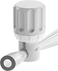
Plastic Noncontact Flow-Adjustment Valves
With no metal parts, these valves are often used for noncontact flow adjustment in wet conditions and harsh environments. All press down on the outside of tubing to adjust flow without contacting the process media. They can be used with any media that’s chemically compatible with your tubing.
Valves with a closed body securely hold tubing in place.
Dial handles are marked with a 1 to 10 mm scale that allows you to make repeatable adjustments.
![]() For technical drawings and 3-D models, click on a part number.
For technical drawings and 3-D models, click on a part number.
- Valve Type: Pinch
- For Use With: Water, Oil, Argon, Butane, Deionized Water, Krypton, Neon, Propane, Xenon
Threaded Balancing Valves
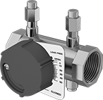
- Valve Type: Ball
- For Use With: Water
- Seal Material: EPDM Rubber
- Specifications Met: CSA Certified
Thread these balancing valves onto pipe—they help you measure the pressure differential across the valve as well as change the flow rate to components in your system. Sometimes called circuit setters, they’re used in HVAC systems and other systems that require even flow distribution. To see what percentage they’re open, there’s an arrow on these valves that’s connected to their measuring plate. Readout ports on both sides let you attach flow measurement tools, such as pressure gauges and probes, which help you track how much the valves reduce flow. Open these valves to a saved percentage by using their memory shutoff function.
Flow coefficient (Cv) is the amount of water (in gallons per minute) at 60° F that will flow through a fully open valve with a difference of 1 psi between the inlet and the outlet.
![]() For technical drawings and 3-D models, click on a part number.
For technical drawings and 3-D models, click on a part number.
| Pipe Size | Flow Coefficient (Cv) | Maximum Pressure | Temperature Range, °F | End-to-End Length | Each | |
Brass Body | ||||||
|---|---|---|---|---|---|---|
NPT Female × NPT Female | ||||||
| 1/2 | 1.52 | 400 psi @ 250° F | 0° to 250° | 3" | 0000000 | 0000000 |
| 3/4 | 2.75 | 400 psi @ 250° F | 0° to 250° | 3 1/16" | 0000000 | 000000 |
| 1 | 5.75 | 400 psi @ 250° F | 0° to 250° | 3 13/16" | 0000000 | 000000 |
| 1 1/4 | 12.5 | 400 psi @ 250° F | 0° to 250° | 4 7/16" | 0000000 | 000000 |
| 1 1/2 | 19.9 | 400 psi @ 250° F | 0° to 250° | 4 7/16" | 0000000 | 000000 |
| 2 | 40 | 400 psi @ 250° F | 0° to 250° | 5 3/16" | 0000000 | 000000 |
| 2 1/2 | 65 | 400 psi @ 250° F | 0° to 250° | 6" | 0000000 | 00000000 |
| 3 | 112 | 400 psi @ 250° F | 0° to 250° | 6 1/2" | 0000000 | 00000000 |
Solder-Connect Balancing Valves
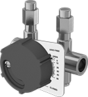
- Valve Type: Ball
- For Use With: Water
- Seal Material: EPDM Rubber
- Specifications Met: CSA Certified
Attach these balancing valves using solder—they help you measure the difference in pressure across the valve and adjust the flow rate to system components. Also known as circuit setters, they’re often used in systems that need an even distribution of flow, such as HVAC systems. To check what percentage they’re open, there’s an arrow on these valves that’s connected to their measuring plate. There are readout ports on both sides for connecting flow measurement tools, such as pressure gauges and probes, which help you track how much the valves reduce flow. Use the memory shutoff function to open them to a saved setting.
Flow coefficient (Cv) is the amount of water (in gallons per minute) at 60° F that will flow through a fully open valve with a difference of 1 psi between the inlet and the outlet.
![]() For technical drawings and 3-D models, click on a part number.
For technical drawings and 3-D models, click on a part number.
| For Tube OD | Flow Coefficient (Cv) | Maximum Pressure | Temperature Range, °F | End-to-End Length | Stem Type | Each | |
Brass Body | |||||||
|---|---|---|---|---|---|---|---|
Solder Connect × Solder Connect | |||||||
| 1/2" | 1.75 | 200 psi @ 250° F, 250 psi @ 225° F, 300 psi @ 200° F | 0° to 250° | 2 15/16" | Nonrising | 0000000 | 0000000 |
| 3/4" | 3.4 | 200 psi @ 250° F, 250 psi @ 225° F, 300 psi @ 200° F | 0° to 250° | 3 9/16" | Nonrising | 0000000 | 000000 |
| 1" | 5.75 | 200 psi @ 250° F, 250 psi @ 225° F, 300 psi @ 200° F | 0° to 250° | 4 5/16" | Nonrising | 0000000 | 000000 |