


For Use With For Use With |
|---|
Body Material Body Material |
|---|
|
System of Measurement System of Measurement |
|---|
|
Thread Size Thread Size |
|---|
Thread Type Thread Type | Show |
|---|
Thread Type Thread Type | Hide |
|---|
Valve Function Valve Function |
|---|
|
Connection Style Connection Style |
|---|
 |
| Threaded |
| Flared |
 |
| Quick Disconnect |
Ball Material Ball Material |
|---|
|
Overall Length Overall Length |
|---|
Maximum Pressure Maximum Pressure |
|---|
Seal Material Seal Material |
|---|
|
Vacuum Rating Vacuum Rating |
|---|
|
Valve Operation Valve Operation |
|---|
|
Maximum Temperature Maximum Temperature |
|---|
|
Flow Coefficient (Cv) Flow Coefficient (Cv) |
|---|
|
|
|


RoHS (Restriction of Hazardous Substances) RoHS (Restriction ofHazardous Substances) |
|---|
|
REACH (Registration, Evaluation, Authorization and Restriction of Chemicals) REACH (Registration,Evaluation, Authorization and Restriction of Chemicals) |
|---|
|
How to Measure Threaded Pipe Size
More
How to Identify and Measure Fittings
Pipe size is an industry designation, not the actual size. View information about how to measure threaded and unthreaded pipe and pipe fittings.
More
About Backflow-Prevention Valves
More
About Actuated On/Off Valves
More
About On/Off Valves
More
How to Measure Fittings
Pipe size is an industry designation, not the actual size. View information about how to measure threaded and unthreaded pipe and pipe fittings.
More
About Precision Flow-Adjustment Valves
More
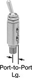
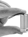
Fast-Acting Compact Threaded On/Off Valves
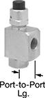
Compact
Push Button
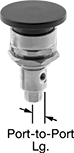
Often used in testing and sampling applications, these valves open and close with the push of a button. They’re also known as push-button valves and are designed for installation in tight spots.
Normally open valves close when the button is pushed and spring open when the button is released.
Normally closed valves open when the button is pushed and spring closed when the button is released.
Flow coefficient (Cv) is the amount of water (in gallons per minute) at 60° F that will flow through a fully open valve with a difference of 1 psi between the inlet and the outlet.
![]() For technical drawings and 3-D models, click on a part number.
For technical drawings and 3-D models, click on a part number.
- Valve Type: Stem
- For Use With: Air, Oil, Water
- Seal Material: Buna-N Rubber
Compact Push Button | Mushroom Push Button | |||||||
|---|---|---|---|---|---|---|---|---|
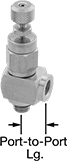
| Thread Size | Flow Coefficient (Cv) | Max. Pressure | Temperature Range, °F | Port-to-Port Lg. | Each | Each | ||
Normally Open | ||||||||
UNF Female × UNF Female | ||||||||
| 10-32 | 0.18 | 150 psi @ 180° F | 35° to 230° | 5/16" | 000000 | 00 | 0000000 | 000000 |
Normally Closed | ||||||||
UNF Female × UNF Female | ||||||||
| 10-32 | 0.12 | 300 psi @ 180° F | 35° to 230° | 5/16" | 0000000 | 000000 | 0000000 | 00000 |
Miniature Threaded On/Off Valves
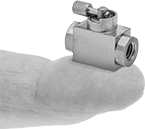
- Valve Type: Ball
- For Use With: Air, Argon, Helium, Krypton, Neon, Water, Xenon
- Seal Material: EPDM Rubber
With 10-32 UNF threads and a body less than 3/4” long, these valves are often used to control flow in miniature pipelines. They have a 303 stainless steel body for good corrosion resistance. All are standard port, so they slightly restrict flow.
Flow coefficient (Cv) is the amount of water (in gallons per minute) at 60° F that will flow through a fully open valve with a difference of 1 psi between the inlet and the outlet.
![]() For technical drawings and 3-D models, click on a part number.
For technical drawings and 3-D models, click on a part number.
| Thread Size | Flow Coefficient (Cv) | Max. Pressure | Temperature Range, °F | Vacuum Rating, in. of Hg | End-to-End Lg. | Each | |
303 Stainless Steel Body | |||||||
|---|---|---|---|---|---|---|---|
UNF Female × UNF Female | |||||||
| 10-32 | 0.1 | 250 psi @ 150° F | -60° to 300° | 25 | 11/16" | 0000000 | 0000000 |
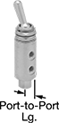
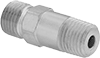
Fast-Acting Panel-Mount Threaded On/Off Valves
Open and close these valves with the flip of the toggle switch. Commonly used for equipment testing and gas sampling, they have threads and a hex nut below the handle for installation in instrument panels.
Manual-return valves remain open or closed when the toggle is moved into position.
Spring-return valves automatically close when the toggle is released.
Flow coefficient (Cv) is the amount of water (in gallons per minute) at 60° F that will flow through a fully open valve with a difference of 1 psi between the inlet and the outlet.
![]() For technical drawings and 3-D models, click on a part number.
For technical drawings and 3-D models, click on a part number.
- Valve Type: Stem
- For Use With:
Buna-N Rubber Seal: Water, Oil, Air
All Other Valves: Water, Oil, Air, Argon, Helium, Krypton, Neon, Xenon
| Pipe Size | Thread Size | Flow Coefficient (Cv) | Max. Pressure | Temperature Range, °F | Toggle Switch Type | Port-to-Port Lg. | Panel Cutout Dia. | Each | |
Brass Body—Buna-N Rubber Seal | |||||||||
|---|---|---|---|---|---|---|---|---|---|
NPT Male × UNF Female | |||||||||
| 1/8 | 10-32 | 7.3 | 150 psi @ 70° F | 35° to 230° | Manual Return | 5/16" | 15/32" | 0000000 | 000000 |
| 1/8 | 10-32 | 8 | 150 psi @ 70° F | 35° to 230° | Manual Return | 5/16" | 15/32" | 0000000 | 00000 |
| 1/8 | 10-32 | 8 | 150 psi @ 70° F | 35° to 230° | Spring Return | 5/16" | 15/32" | 0000000 | 00000 |
UNF Female × UNF Female | |||||||||
| __ | 10-32 | 6.8 | 150 psi @ 70° F | 35° to 230° | Spring Return | 5/16" | 15/32" | 0000000 | 00000 |
| __ | 10-32 | 7.3 | 150 psi @ 70° F | 35° to 230° | Manual Return | 5/16" | 15/32" | 0000000 | 00000 |
Miniature Threaded On/Off Valves for Chemicals
- Valve Type: Ball
- For Use With: Air, Argon, Butane, Carbon Dioxide, Chlorine, Citric Acid, Diesel Fuel, Ethylene Glycol, Fuel Oil, Gasoline, Helium, Hydrochloric Acid, Isopropyl Alcohol, Kerosene, Krypton, Mineral Spirits, Natural Gas, Neon, Nitric Acid, Nitrogen, Oil, Oxygen, Phosphoric Acid, Propane, Salt Water, Soap Solutions, Sodium Hydroxide, Sodium Hypochlorite, Sulfuric Acid, Toluene, Water, Xenon, Xylene
- Ball Material: 316 Stainless Steel
- Seal Material: Fluoroelastomer Rubber
- Seat Material: Fluoroelastomer Rubber
To withstand aggressive and corrosive solutions in miniature chemical-processing pipelines, these tiny valves have a chemical-resistant fluoroelastomer seal and a corrosion-resistant 303 stainless steel body. They are standard port, so they slightly restrict flow.
Flow coefficient (Cv) is the amount of water (in gallons per minute) at 60° F that will flow through a fully open valve with a difference of 1 psi between the inlet and the outlet.
![]() For technical drawings and 3-D models, click on a part number.
For technical drawings and 3-D models, click on a part number.
| Thread Size | Flow Coefficient (Cv) | Max. Pressure | Temperature Range, °F | Vacuum Rating, in. of Hg | End-to-End Lg. | Each | |
303 Stainless Steel Body | |||||||
|---|---|---|---|---|---|---|---|
UNF Female × UNF Female | |||||||
| 10-32 | 0.1 | 250 psi @ 150° F | 0° to 400° | 25 | 11/16" | 0000000 | 0000000 |
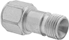
On/Off Valves with 37° Flared Tube Fittings for Fuel
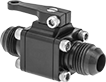
- Valve Type: Ball
- For Use With: Diesel Fuel, Fuel Oil, Gasoline
- Seal Material: PTFE Plastic
These valves have 37° flared tube fittings that form a tight seal on metal tubing lines to transfer diesel fuel, fuel oil, and gasoline. All are full port, so they do not restrict flow.
![]() For technical drawings and 3-D models, click on a part number.
For technical drawings and 3-D models, click on a part number.
| Thread Size | For Tube OD | Max. Pressure | Temperature Range, °F | End-to-End Lg. | Each | |
Aluminum Body | ||||||
|---|---|---|---|---|---|---|
37° Flared × 37° Flared | ||||||
| 9/16"-18 | 3/8" | 200 psi @ 70° F | -40° to 250° | 2 9/16" | 0000000 | 0000000 |
| 3/4"-16 | 1/2" | 200 psi @ 70° F | -40° to 250° | 2 11/16" | 0000000 | 000000 |
| 7/8"-14 | 5/8" | 200 psi @ 70° F | -40° to 250° | 3 1/4" | 0000000 | 000000 |
| 1 1/16"-12 | 3/4" | 200 psi @ 70° F | -40° to 250° | 3 7/16" | 0000000 | 000000 |
| 1 5/16"-12 | 1" | 200 psi @ 70° F | -40° to 250° | 4 5/16" | 0000000 | 000000 |
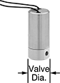
Miniature Solenoid On/Off Valves
- For Use With: Water, Air, Argon, Helium, Neon, Xenon, Krypton
- Seal Material: Fluoroelastomer Rubber
Less than half the size of our other compact valves, these have small pipe connections for miniature lines. They operate on electricity to automatically start and stop flow.
Valves are normally closed unless actuated. They don’t require a minimum pressure drop between the inlet and outlet for operation. Body is 303 stainless steel for good corrosion resistance. The actuator is directly mounted to the valve body to minimize movement and reduce wear.
Flow coefficient (Cv) is the amount of water (in gallons per minute) at 60° F that will flow through a fully open valve with a difference of 1 psi between the inlet and the outlet.
![]() For technical drawings and 3-D models, click on a part number.
For technical drawings and 3-D models, click on a part number.
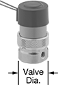
| Thread Size | Gender | Thread Type | Flow Coefficient (Cv) | Max. Pressure | Pressure Drop | Temp. Range, °F | Valve Dia. | O'all Ht. | Each | |
303 Stainless Steel Body with Wire Leads | ||||||||||
|---|---|---|---|---|---|---|---|---|---|---|
Normally Closed—12V DC | ||||||||||
| 10-32 | Female | UNF | 0.013 | 100 psi @ 140° F | Zero Pressure Drop | 35° to 140° | 11/16" | 1 11/16" | 0000000 | 000000 |
| 10-32 | Female | UNF | 0.038 | 100 psi @ 140° F | Zero Pressure Drop | 35° to 140° | 11/16" | 1 11/16" | 0000000 | 00000 |
| 10-32 | Female | UNF | 0.07 | 30 psi @ 140° F | Zero Pressure Drop | 35° to 140° | 11/16" | 1 11/16" | 0000000 | 00000 |
Normally Closed—24V DC | ||||||||||
| 10-32 | Female | UNF | 0.013 | 100 psi @ 140° F | Zero Pressure Drop | 35° to 140° | 11/16" | 1 11/16" | 0000000 | 00000 |
| 10-32 | Female | UNF | 0.038 | 100 psi @ 140° F | Zero Pressure Drop | 35° to 140° | 11/16" | 1 11/16" | 0000000 | 00000 |
| 10-32 | Female | UNF | 0.07 | 30 psi @ 140° F | Zero Pressure Drop | 35° to 140° | 11/16" | 1 11/16" | 0000000 | 00000 |
Threaded Precision Flow-Adjustment Valves
Also known as needle valves, these adjust flow in small increments for metering, sampling, and other applications requiring fine flow control. Turn the handle to adjust flow. All valves have metal-to-metal seats that resist temperature fluctuations.
303 stainless steel valves are more corrosion resistant than brass and steel valves.
316 stainless steel valves have the best corrosion resistance.
Valves with packing have a nut that can be tightened to compress the packing if it leaks.
Flow coefficient (Cv) is the amount of water (in gallons per minute) at 60° F that will flow through a fully open valve with a difference of 1 psi between the inlet and the outlet.
![]() For technical drawings and 3-D models, click on a part number.
For technical drawings and 3-D models, click on a part number.
- Valve Type: Needle
- For Use With: Water, Oil, Air, Argon, Helium, Krypton, Neon, Xenon
| Thread Size | Flow Coefficient (Cv) | Max. Pressure | Temperature Range, °F | Packing Material | Port-to-Port Lg. | Each | |
303 Stainless Steel Body with Knob Handle | |||||||
|---|---|---|---|---|---|---|---|
| 10-32 | 0.02 | 300 psi @ 70° F | 0° to 430° | Fluoroelastomer Rubber | 5/16" | 00000000 | 000000 |
316 Stainless Steel Body with Knob Handle | |||||||
| 10-32 | 0.02 | 300 psi @ 70° F | 0° to 430° | Fluoroelastomer Rubber | 5/16" | 00000000 | 00000 |
Compact Solenoid Flow-Adjustment Valves
- For Use With: Air, Argon, Helium, Krypton, Neon, Xenon
- Seal Material: Fluoroelastomer Rubber
Available in smaller pipe sizes than other solenoid flow-adjustment valves, these are often used with gas controllers and analytical instrumentation. They adjust and regulate flow based on the intensity of the electrical signal into the valve and are often integrated into PLC systems for automatic control over the valve position based on system conditions. They are normally closed unless actuated. Valves don’t require a pressure drop for operation. The actuator is directly mounted to the valve body to minimize movement and reduce wear.
![]() For technical drawings and 3-D models, click on a part number.
For technical drawings and 3-D models, click on a part number.
| Thread Size | Gender | Thread Type | Max. Pressure | Pressure Drop | Min. Pressure Drop Required | Temp. Range, °F | Input Signal Voltage | Valve Dia. | O'all Ht. | Each | |
Nickel-Plated Brass Body with Wire Leads | |||||||||||
|---|---|---|---|---|---|---|---|---|---|---|---|
Normally Closed—12V DC | |||||||||||
| 10-32 | Female | UNF | 100 psi @ 70° F | Zero Pressure Drop | None | 35° to 120° | 0V DC-10V DC | 7/8" | 1 9/16" | 0000000 | 000000 |
Normally Closed—24V DC | |||||||||||
| 10-32 | Female | UNF | 100 psi @ 70° F | Zero Pressure Drop | None | 35° to 120° | 0V DC-20V DC | 7/8" | 1 9/16" | 0000000 | 00000 |
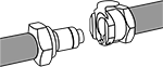
Pressure-Driven Threaded Diverting Valves


- Valve Type: Shuttle
- For Use With: Air, Argon, Helium, Krypton, Neon, Oil, Water, Xenon
- Seal Material:
UNF Thread Type: Buna-N Rubber
NPT Thread Type: Nitrile Rubber
Also known as shuttle valves, these automatically switch the inlet source as pressure changes; they always direct flow from the higher-pressure side-port inlet to the top-port outlet. They cannot shut off flow.
![]() For technical drawings and 3-D models, click on a part number.
For technical drawings and 3-D models, click on a part number.
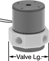
Solenoid Diverting Valves for Chemicals
- For Use With: Acetone, Air, Ammonia, Argon, Chlorine, Citric Acid, Deionized Water, Diesel Fuel, Ethylene Glycol, Fuel Oil, Helium, Hydrochloric Acid, Krypton, Methanol, Neon, Nitric Acid, Oil, Oxygen, Phosphoric Acid, Salt Water, Sulfuric Acid, Water, Xenon, Xylene
- Seal Material: PTFE Plastic
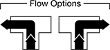
Often used for chemical analysis and other laboratory testing, these valves have a PTFE seal and body to withstand aggressive and corrosive solutions. All operate on electricity to automatically divert flow between ports. They do not require a pressure drop for operation. Any port can be used as an inlet or an outlet. Valves can direct flow from the inlet port to either outlet port. They cannot shut off flow. The actuator is mounted directly to the valve body to minimize movement and reduce wear.
Flow coefficient (Cv) is the amount of water (in gallons per minute) at 60° F that will flow through a fully open valve with a difference of 1 psi between the inlet and the outlet.
![]() For technical drawings and 3-D models, click on a part number.
For technical drawings and 3-D models, click on a part number.
Mounting Holes | ||||||||||||||
|---|---|---|---|---|---|---|---|---|---|---|---|---|---|---|
| Thread Size | Flow Pattern | Flow Coefficient (Cv) | Max. Pressure | Pressure Drop | Min. Pressure Drop Required | Temp. Range, °F | Actuation Time | Valve Lg. | O'all Ht. | Mounting Fasteners Included | No. of | Thread Size | Each | |
PTFE Plastic Body with Wire Leads—12V DC | ||||||||||||||
UNF Female × UNF Female × UNF Female | ||||||||||||||
| 1/4"-28 | L-Pattern | 10.57 | 30 psi @ 70° F | Zero Pressure Drop | None | 35° to 155° | 0.02 sec. | 1 1/2" | 1 13/16" | No | 7 | 4-40 | 0000000 | 0000000 |
| 10-32 | L-Pattern | 2.64 | 30 psi @ 70° F | Zero Pressure Drop | None | 35° to 155° | 0.02 sec. | 3/4" | 1 3/16" | No | 5 | 2-56 | 0000000 | 00000 |
PTFE Plastic Body with Wire Leads—24V DC | ||||||||||||||
UNF Female × UNF Female × UNF Female | ||||||||||||||
| 1/4"-28 | L-Pattern | 10.57 | 30 psi @ 70° F | Zero Pressure Drop | None | 35° to 155° | 0.02 sec. | 1 1/2" | 1 13/16" | No | 7 | 4-40 | 0000000 | 000000 |
| 10-32 | L-Pattern | 2.64 | 30 psi @ 70° F | Zero Pressure Drop | None | 35° to 155° | 0.02 sec. | 3/4" | 1 3/16" | No | 5 | 2-56 | 0000000 | 00000 |
Compact Threaded Check Valves
- For Use With: Air, Nitrogen, Water
- Ball Material: 304 Stainless Steel
- Seal Material: See table
With a shorter end-to-end length than other check valves, these fit in tight spaces. They open to allow flow in one direction and close when flow stops or reverses.
303 stainless steel valves are more corrosion resistant than brass valves.
Flow coefficient (Cv) is the amount of water (in gallons per minute) at 60° F that will flow through a fully open valve with a difference of 1 psi between the inlet and the outlet.
![]() For technical drawings and 3-D models, click on a part number.
For technical drawings and 3-D models, click on a part number.
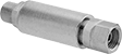
Threaded Flow Control Orifices


Connect these orifices to threaded pipe, or insert them into threaded holes. Also known as flow restrictors and precision orifice valves, they are used to throttle, vent, bleed, or regulate the flow of liquids and gases.
Stainless steel orifices are more corrosion resistant than brass orifices.
316 stainless steel orifices have better corrosion resistance than 303 stainless steel orifices.
![]() For technical drawings and 3-D models, click on a part number.
For technical drawings and 3-D models, click on a part number.
- For Use With: Air, Argon, Carbon Dioxide, Helium, Neon, Nitrogen, Oil, Water, Xenon
- Max. Pressure: 2,000 psi @ 70° F
- Temperature Range: 35° to 200° F
Available Orifice Diameters | ||
|---|---|---|
| Orifice Dia. | Water Flow | Air Flow |
| 0.01" | 0.016 gpm @ 40 psi | 0.1 scfm @ 40 psi |
| 0.016" | 0.035 gpm @ 40 psi | 0.2 scfm @ 40 psi |
| 0.018" | 0.046 gpm @ 40 psi | 0.2 scfm @ 40 psi |
| 0.02" | 0.056 gpm @ 40 psi | 0.3 scfm @ 40 psi |
| 0.021" | 0.061 gpm @ 40 psi | 0.3 scfm @ 40 psi |
| 0.023" | 0.076 gpm @ 40 psi | 0.4 scfm @ 40 psi |
| 0.024" | 0.082 gpm @ 40 psi | 0.4 scfm @ 40 psi |
| 0.025" | 0.089 gpm @ 40 psi | 0.5 scfm @ 40 psi |
| 0.026" | 0.101 gpm @ 40 psi | 0.5 scfm @ 40 psi |
| 0.028" | 0.114 gpm @ 40 psi | 0.6 scfm @ 40 psi |
| 0.029" | 0.12 gpm @ 40 psi | 0.6 scfm @ 40 psi |
| 0.032" | 0.152 gpm @ 40 psi | 0.7 scfm @ 40 psi |
| 0.033" | 0.158 gpm @ 40 psi | 0.8 scfm @ 40 psi |
| 0.035" | 0.177 gpm @ 40 psi | 0.9 scfm @ 40 psi |
| 0.038" | 0.202 gpm @ 40 psi | 1.1 scfm @ 40 psi |
| 0.04" | 0.228 gpm @ 40 psi | 1.2 scfm @ 40 psi |
| 0.042" | 0.247 gpm @ 40 psi | 1.3 scfm @ 40 psi |
| 0.047" | 0.304 gpm @ 40 psi | 1.6 scfm @ 40 psi |
| 0.052" | 0.373 gpm @ 40 psi | 2 scfm @ 40 psi |
| 0.055" | 0.43 gpm @ 40 psi | 2.2 scfm @ 40 psi |
| 0.063" | 0.557 gpm @ 40 psi | 2.8 scfm @ 40 psi |
- For Use With: Air, Argon, Carbon Dioxide, Helium, Neon, Nitrogen, Oil, Water, Xenon
- Max. Pressure: 100 psi @ 70° F
- Temperature Range: Not Rated
Available Orifice Diameters | ||
|---|---|---|
| Orifice Dia. | Water Flow | Air Flow |
| 0.01" | 0.016 gpm @ 40 psi | 0.1 scfm @ 40 psi |
| 0.016" | 0.035 gpm @ 40 psi | 0.2 scfm @ 40 psi |
| 0.018" | 0.046 gpm @ 40 psi | 0.2 scfm @ 40 psi |
| 0.02" | 0.056 gpm @ 40 psi | 0.3 scfm @ 40 psi |
| 0.021" | 0.061 gpm @ 40 psi | 0.3 scfm @ 40 psi |
| 0.023" | 0.076 gpm @ 40 psi | 0.4 scfm @ 40 psi |
| 0.024" | 0.082 gpm @ 40 psi | 0.4 scfm @ 40 psi |
| 0.025" | 0.089 gpm @ 40 psi | 0.5 scfm @ 40 psi |
| 0.026" | 0.101 gpm @ 40 psi | 0.5 scfm @ 40 psi |
| 0.028" | 0.114 gpm @ 40 psi | 0.6 scfm @ 40 psi |
| 0.029" | 0.12 gpm @ 40 psi | 0.6 scfm @ 40 psi |
| 0.032" | 0.152 gpm @ 40 psi | 0.7 scfm @ 40 psi |
| 0.033" | 0.158 gpm @ 40 psi | 0.8 scfm @ 40 psi |
| 0.035" | 0.177 gpm @ 40 psi | 0.9 scfm @ 40 psi |
| 0.038" | 0.202 gpm @ 40 psi | 1.1 scfm @ 40 psi |
| 0.04" | 0.228 gpm @ 40 psi | 1.2 scfm @ 40 psi |
| 0.042" | 0.247 gpm @ 40 psi | 1.3 scfm @ 40 psi |
| 0.047" | 0.304 gpm @ 40 psi | 1.6 scfm @ 40 psi |
| 0.052" | 0.373 gpm @ 40 psi | 2 scfm @ 40 psi |
| 0.055" | 0.43 gpm @ 40 psi | 2.2 scfm @ 40 psi |
| 0.063" | 0.557 gpm @ 40 psi | 2.8 scfm @ 40 psi |
| Thread Size | Lg. | Each | |
| 10-32 | 7/16" | 0000000 | 000000 |
- For Use With: Air, Argon, Carbon Dioxide, Helium, Neon, Nitrogen, Oil, Water, Xenon
- Max. Pressure: 4,000 psi @ 70° F
- Temperature Range: 35° to 200° F
Available Orifice Diameters | ||
|---|---|---|
| Orifice Dia. | Water Flow | Air Flow |
| 0.01" | 0.016 gpm @ 40 psi | 0.1 scfm @ 40 psi |
| 0.016" | 0.035 gpm @ 40 psi | 0.2 scfm @ 40 psi |
| 0.018" | 0.046 gpm @ 40 psi | 0.2 scfm @ 40 psi |
| 0.02" | 0.056 gpm @ 40 psi | 0.3 scfm @ 40 psi |
| 0.021" | 0.061 gpm @ 40 psi | 0.3 scfm @ 40 psi |
| 0.023" | 0.076 gpm @ 40 psi | 0.4 scfm @ 40 psi |
| 0.024" | 0.082 gpm @ 40 psi | 0.4 scfm @ 40 psi |
| 0.025" | 0.089 gpm @ 40 psi | 0.5 scfm @ 40 psi |
| 0.026" | 0.101 gpm @ 40 psi | 0.5 scfm @ 40 psi |
| 0.028" | 0.114 gpm @ 40 psi | 0.6 scfm @ 40 psi |
| 0.029" | 0.12 gpm @ 40 psi | 0.6 scfm @ 40 psi |
| 0.032" | 0.152 gpm @ 40 psi | 0.7 scfm @ 40 psi |
| 0.033" | 0.158 gpm @ 40 psi | 0.8 scfm @ 40 psi |
| 0.035" | 0.177 gpm @ 40 psi | 0.9 scfm @ 40 psi |
| 0.038" | 0.202 gpm @ 40 psi | 1.1 scfm @ 40 psi |
| 0.04" | 0.228 gpm @ 40 psi | 1.2 scfm @ 40 psi |
| 0.042" | 0.247 gpm @ 40 psi | 1.3 scfm @ 40 psi |
| 0.047" | 0.304 gpm @ 40 psi | 1.6 scfm @ 40 psi |
| 0.052" | 0.373 gpm @ 40 psi | 2 scfm @ 40 psi |
| 0.055" | 0.43 gpm @ 40 psi | 2.2 scfm @ 40 psi |
| 0.063" | 0.557 gpm @ 40 psi | 2.8 scfm @ 40 psi |
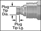
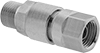
International Standard ISO Minimal-Spill
Quick-Disconnect Hose Couplings for Hydraulic Fluid
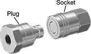
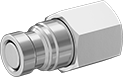
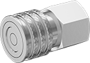


Also known as flush-face couplings, the plugs and sockets have a flat face, which allows them to mate close against each other, reducing fluid loss when connecting and disconnecting the line. A complete coupling consists of a plug and a socket (both sold separately) that connect and disconnect quickly. Use them when you need frequent access to a line. All of the International Standard ISO Minimal-Spill quick-disconnect plugs are compatible with any of the International Standard ISO Minimal-Spill quick-disconnect sockets of the same coupling size, regardless of the pipe size. Couplings are compatible with ISO 16028 Parker FEM, ISO 16028 Perfecting HT, and ISO 16028 Snap-Tite 74 couplings. Also known as double shut-off couplings, the plugs and sockets both have a shut-off valve that stops the flow when the coupling is separated. They are zinc-plated steel, which has excellent strength and durability and fair corrosion resistance.
Plugs are also known as nipples.
Sockets are push-to-connect style. To connect, push the plug into the socket until you hear a click. To disconnect, slide the sleeve on the socket forward until the plug ejects.
Note: To ensure a correct fit, make sure that the plug and socket have the same coupling size. Pressure ratings are given for static (constant) pressure conditions.
Warning: Never attempt to connect or disconnect couplings when operating at maximum pressure. Stop the flow before you disconnect the line.
![]() For technical drawings and 3-D models, click on a part number.
For technical drawings and 3-D models, click on a part number.
- Maximum Pressure: See table
- Temperature Range: -20° to 212° F
- Compatible With: ISO 16028 Parker FEM, ISO 16028 Perfecting HT, ISO 16028 Snap-Tite 74
- Specifications Met: ISO 16028
- Maximum Pressure: See table
- Temperature Range: -20° to 212° F
- Compatible With: ISO 16028 Parker FEM, ISO 16028 Perfecting HT, ISO 16028 Snap-Tite 74
- Specifications Met: ISO 16028
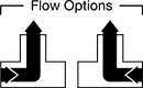
Straight-Flow Rectangular Manifolds
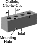
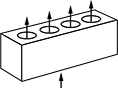
Unlike other manifolds, which have an inlet on either end, these have one inlet on the opposite side from the outlets. This design allows fluid or air to follow a straight path, improving flow through your system. It also frees up the ends of the manifold, so you can mount it in corners and in narrow spaces. Manifolds are also known as headers. They have mounting holes, so you can mount from the top or side.
Anodized aluminum manifolds are the industry standard for the most common types of applications. They are lighter in weight than other metal manifolds and have good corrosion resistance. These manifolds are anodized for a black finish.
Use a plug (sold separately) to close off any unused inlets and outlets.
![]() For technical drawings and 3-D models, click on a part number.
For technical drawings and 3-D models, click on a part number.
- For Use With: Air, Water, Hydraulic Fluid
- Temperature Range: -10° to 200° F
- Maximum Pressure:
Air: 1,000 psi @ 72° F
Water: 1,000 psi @ 72° F
Hydraulic Fluid: 3,000 psi @ 72° F
Inlet | Outlet | ||||||||||
|---|---|---|---|---|---|---|---|---|---|---|---|
| No. of Outlets | Thread Size | Dash Size | Thread Size | Dash Size | Lg. | Wd. | Ht. | Outlet Ctr.-to-Ctr. | Color | Each | |
Standard Outlet Spacing | |||||||||||
| 2 | 9/16"-18 | 6 | 7/16"-20 | 4 | 2 1/8" | 1 1/4" | 1 1/4" | 7/8" | Black | 00000000 | 000000 |
| 2 | 1 1/16"-12 | 12 | 3/4"-16 | 8 | 4" | 2" | 2" | 1 1/2" | Black | 00000000 | 00000 |
| 3 | 1 1/16"-12 | 12 | 3/4"-16 | 8 | 5 1/2" | 2" | 2" | 1 1/2" | Black | 00000000 | 00000 |
| 3 | 1 5/16"-12 | 16 | 1 1/16"-12 | 12 | 7" | 2 1/2" | 2 1/2" | 2" | Black | 00000000 | 000000 |
| 4 | 9/16"-18 | 6 | 7/16"-20 | 4 | 3 7/8" | 1 1/4" | 1 1/4" | 7/8" | Black | 00000000 | 00000 |
| 4 | 3/4"-16 | 8 | 9/16"-18 | 6 | 4 3/4" | 1 1/2" | 1 1/2" | 1" | Black | 00000000 | 00000 |
| 4 | 1 1/16"-12 | 12 | 3/4"-16 | 8 | 7" | 2" | 2" | 1 1/2" | Black | 00000000 | 00000 |
| 6 | 9/16"-18 | 6 | 7/16"-20 | 4 | 5 5/8" | 1 1/4" | 1 1/4" | 7/8" | Black | 00000000 | 00000 |
| 6 | 1 5/16"-12 | 16 | 1 1/16"-12 | 12 | 13" | 2 1/2" | 2 1/2" | 2" | Black | 00000000 | 000000 |
| 8 | 7/16"-20 | 4 | 5/16"-24 | 2 | 6 1/4" | 1" | 1" | 3/4" | Black | 00000000 | 00000 |
| 8 | 9/16"-18 | 6 | 7/16"-20 | 4 | 7 3/8" | 1 1/4" | 1 1/4" | 7/8" | Black | 00000000 | 00000 |
Welding Gas Check Valves for Regulators
Stop the reverse flow of gas in your regulator. Check valves do not stop flashbacks.
Welding Gas Check Valves for Torches
Stop the reverse flow of gas in your torch. Check valves do not stop flashbacks.
Max. Pressure, psi | Male Hose Connection | Female Hose Connection | ||||||||||
|---|---|---|---|---|---|---|---|---|---|---|---|---|
| Oxygen | Acetylene | Hydrogen | Propane | Thread Direction | Thread Size | Thread Type | Thread Direction | Thread Size | Thread Type | Material | Each | |
| 125 | __ | __ | __ | Right Hand | 3/8"-24 | UNF | Right Hand | 3/8"-24 | UNF | Brass | 000000 | 000000 |
| 125 | __ | __ | __ | Right Hand | 9/16"-18 | UNF | Right Hand | 9/16"-18 | UNF | Brass | 000000 | 00000 |
| __ | 50 | 50 | 50 | Left Hand | 3/8"-24 | UNF | Left Hand | 3/8"-24 | UNF | Brass | 000000 | 00000 |
| __ | 50 | 50 | 50 | Left Hand | 9/16"-18 | UNF | Left Hand | 9/16"-18 | UNF | Brass | 000000 | 00000 |
Welding Gas Flashback Arresters for Regulators
Attach these arresters to the outlet connection of a regulator on a torch that cuts steel up to 11" thick. Arresters extinguish flames and have a check valve to stop reverse gas flow. They are reusable; resetting is not required after flashback.
Arresters with right-hand threads are for use with oxygen; arresters with left-hand threads are for use with acetylene, hydrogen, and propane.
Male Hose Connection | Female Hose Connection | |||||||
|---|---|---|---|---|---|---|---|---|
| Max. Pressure for Oxygen, psi | Thread Size | Thread Type | Thread Size | Thread Type | Material | Specifications Met | Each | |
| 143 | 9/16"-18 | UNF | 9/16"-18 | UNF | Brass | EN 730, ISO 5175 | 00000000 | 000000 |
Max. Pressure, psi | Male Hose Connection | Female Hose Connection | ||||||||
|---|---|---|---|---|---|---|---|---|---|---|
| Acetylene | Hydrogen | Propane | Thread Size | Thread Type | Thread Size | Thread Type | Material | Specifications Met | Each | |
| 15 | 50 | 50 | 9/16"-18 | UNF | 9/16"-18 | UNF | Brass | EN 730, ISO 5175 | 00000000 | 000000 |
Max. Pressure, psi | Male Hose Connection | Female Hose Connection | |||||||||
|---|---|---|---|---|---|---|---|---|---|---|---|
| Oxygen | Acetylene | Hydrogen | Propane | Thread Size | Thread Type | Thread Size | Thread Type | Material | Specifications Met | Pair | |
| 143 | 15 | 50 | 50 | 9/16"-18 | UNF | 9/16"-18 | UNF | Brass | EN 730, ISO 5175 | 00000000 | 000000 |
Welding Gas Flashback Arresters for Torches
These arresters attach directly to torches that cut steel up to 8" thick. They extinguish flames and have a check valve to stop reverse gas flow. They are reusable; resetting is not required after flashback.
Arresters with right-hand threads are for use with oxygen; arresters with left-hand threads are for use with acetylene, hydrogen, and propane.
Male Hose Connection | Female Hose Connection | |||||||
|---|---|---|---|---|---|---|---|---|
| Max. Pressure for Oxygen, psi | Thread Size | Thread Type | Thread Size | Thread Type | Material | Specifications Met | Each | |
| 143 | 9/16"-18 | UNF | 9/16"-18 | UNF | Brass | EN 730, ISO 5175 | 00000000 | 000000 |
Max. Pressure, psi | Male Hose Connection | Female Hose Connection | ||||||||
|---|---|---|---|---|---|---|---|---|---|---|
| Acetylene | Hydrogen | Propane | Thread Size | Thread Type | Thread Size | Thread Type | Material | Specifications Met | Each | |
| 15 | 50 | 50 | 9/16"-18 | UNF | 9/16"-18 | UNF | Brass | EN 730, ISO 5175 | 00000000 | 000000 |
Max. Pressure, psi | Male Hose Connection | Female Hose Connection | |||||||||
|---|---|---|---|---|---|---|---|---|---|---|---|
| Oxygen | Acetylene | Hydrogen | Propane | Thread Size | Thread Type | Thread Size | Thread Type | Material | Specifications Met | Pair | |
| 143 | 15 | 50 | 50 | 9/16"-18 | UNF | 9/16"-18 | UNF | Brass | EN 730, ISO 5175 | 00000000 | 000000 |