


Flow Pattern Flow Pattern |
|---|
| 4/3 (Closed Center) |
| 4/3 (Exhaust Center) |
Valve Function Valve Function |
|---|
|
Maximum Flow Rate Maximum Flow Rate |
|---|
|
DFARS (Defense Acquisition Regulations Supplement) DFARS (Defense AcquisitionRegulations Supplement) |
|---|
RoHS (Restriction of Hazardous Substances) RoHS (Restriction ofHazardous Substances) |
|---|
|
Matching Flow Diagrams to Replace an Air Directional Control Valve
More
Choosing an Air Directional Control Valve
More
Two-Action Air Directional Control Valves with Full Shut-Off
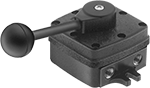
These valves close all ports in the off position to stop equipment in a locked position with air pressure holding it in place. Also known as 4-way and 4/3 closed-center valves, they create two actions, such as extracting and then retracting a double-acting cylinder. They direct airflow from the inlet to your equipment and exhaust return airflow to create motion. Return actuation is by hand, so valves stay actuated and return to their original position only when you move the actuator again.
Flow coefficient (Cv) is a measurement that indicates how much airflow can pass through a valve.
![]() For technical drawings and 3-D models, click on a part number.
For technical drawings and 3-D models, click on a part number.
Overall | |||||||||||||
|---|---|---|---|---|---|---|---|---|---|---|---|---|---|
| No. of Flow Ports | Inlet Size | Outlet Size | Exhaust Connection Type | Max. Flow Rate, scfm @ 100 psi | Flow Coefficient (Cv) | Pressure Range, psi | Vacuum Rating | Lg. | Wd. | Ht. | Mounting Fasteners Included | Each | |
Threaded Female Inlet × Threaded Female Outlet | |||||||||||||
| 4 | 1/4 NPT | 1/4 NPT | Threaded | 125 | 3.4 | 0-145 | Not Rated | 5 5/8" | 4" | 4 3/4" | No | 00000000 | 0000000 |
| 4 | 3/8 NPT | 3/8 NPT | Threaded | 70 | 3 | 0-150 | Not Rated | 6 7/8" | 4 3/4" | 3 3/4" | No | 00000000 | 000000 |
| 4 | 3/8 NPT | 3/8 NPT | Threaded | 70 | 3 | 0-250 | Not Rated | 6 7/8" | 4 3/4" | 3 3/4" | No | 000000000 | 000000 |
| 4 | 1/2 NPT | 1/2 NPT | Threaded | 145 | 6.2 | 0-150 | Not Rated | 9" | 5 5/8" | 4 1/2" | No | 00000000 | 000000 |
| 4 | 1/2 NPT | 1/2 NPT | Threaded | 145 | 6.2 | 0-250 | Not Rated | 9" | 5 5/8" | 4 1/2" | No | 000000000 | 000000 |
Two-Action Air Directional Control Valves with Exhausting Shut-Off
In the off position, these valves exhaust all air pressure, allowing equipment to return to the neutral position. Also known as 4-way and 4/3 exhaust-center valves, they create two actions, such as extracting and then retracting a double-acting cylinder. They direct airflow from the inlet to your equipment and exhaust return airflow to create motion. Return actuation is by hand, so valves stay actuated and return to their original position only when you move the actuator again.
Flow coefficient (Cv) is a measurement that indicates how much airflow can pass through a valve.
![]() For technical drawings and 3-D models, click on a part number.
For technical drawings and 3-D models, click on a part number.
Overall | |||||||||||||
|---|---|---|---|---|---|---|---|---|---|---|---|---|---|
| No. of Flow Ports | Inlet Size | Outlet Size | Exhaust Connection Type | Max. Flow Rate, scfm @ 100 psi | Flow Coefficient (Cv) | Pressure Range, psi | Vacuum Rating | Lg. | Wd. | Ht. | Mounting Fasteners Included | Each | |
Threaded Female Inlet × Threaded Female Outlet | |||||||||||||
| 4 | 1/4 NPT | 1/4 NPT | Threaded | 125 | 3.4 | 0-145 | Not Rated | 5 5/8" | 4" | 4 3/4" | No | 00000000 | 0000000 |
| 4 | 3/8 NPT | 3/8 NPT | Threaded | 70 | 3 | 0-150 | Not Rated | 6 7/8" | 4 3/4" | 3 3/4" | No | 00000000 | 000000 |
| 4 | 1/2 NPT | 1/2 NPT | Threaded | 145 | 6.2 | 0-150 | Not Rated | 9" | 5 5/8" | 4 1/2" | No | 00000000 | 000000 |
Safety-Lockout Air On/Off Valves
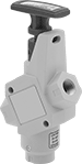
Padlocks that comply with OSHA 29 CFR 1910.147 meet standards for the control of energy sources that could injure workers.
![]() For technical drawings and 3-D models, click on a part number.
For technical drawings and 3-D models, click on a part number.
Flow Rate @ 100 psi | Overall | |||||||||||||
|---|---|---|---|---|---|---|---|---|---|---|---|---|---|---|
| Inlet Pipe Size | Outlet Pipe Size | Exhaust Pipe Size | Flow Coefficient (Cv) | Min. | Max. | Max. Pressure, psi | Temp. Range, °F | Lg. | Wd. | Ht. | For Max. Padlock Shackle Dia. | Specifications Met | Each | |
Aluminum Body | ||||||||||||||
| 1/2 | 1/2 | 3/4 | 4 | 0 scfm | 91 scfm | 300 | 40° to 175° | 4 1/4" | 2" | 9" | 1/4" | OSHA Compliant 29 CFR 1910.147 | 0000000 | 0000000 |
| 3/4 | 3/4 | 3/4 | 4 | 0 scfm | 93 scfm | 300 | 40° to 175° | 4 1/4" | 2" | 9" | 1/4" | OSHA Compliant 29 CFR 1910.147 | 0000000 | 000000 |
| 1 | 1 | 1 1/4 | 9.4 | 0 scfm | 216 scfm | 300 | 40° to 175° | 4 1/4" | 2 1/4" | 9" | 1/4" | OSHA Compliant 29 CFR 1910.147 | 0000000 | 000000 |