Filter by
Body Material
Set Point
Wetted Parts Material
Voltage
Fitting Connection


Fitting Material
Maximum Flow Rate
Maximum Temperature
Flow Measurement Type
Maximum Pressure @ Temperature
Maximum Switching Current @ Voltage
Connects To
Approximate Difference Between Set Point and Reset Point
Set Point Configuration
Export Control Classification Number (ECCN)
DFARS Specialty Metals
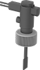
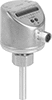
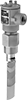
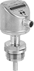
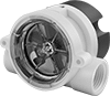
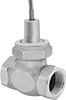
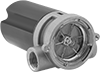
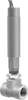
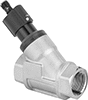
Flow Switches
Inline-Mount Flow Switches
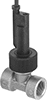
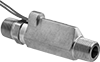
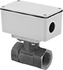
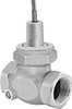

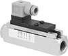
Insertion-Mount Flow Switches