


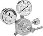
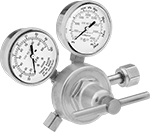
Tank-Mount Pressure-Regulating Valves for Air and Inert Gas
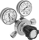 | 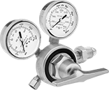 | 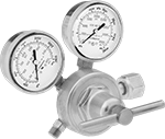 | 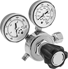 |
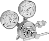
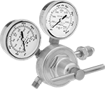
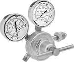
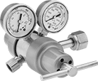
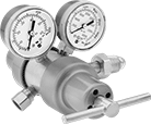
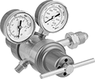
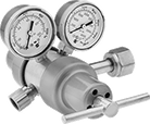
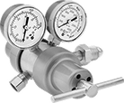
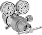
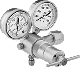
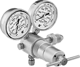
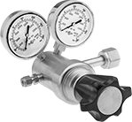
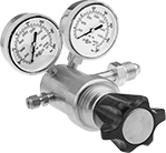
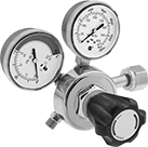
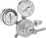
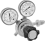
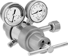
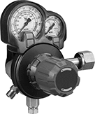
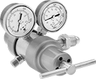
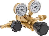
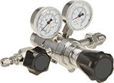
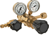
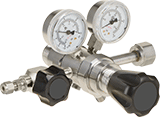
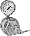
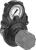
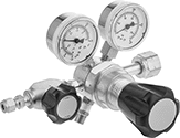
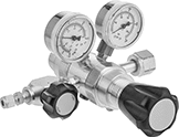
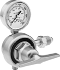
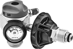
Female Outlet × Female Inlet Single-Stage Valves with Knob | Female Outlet × Male Inlet Single-Stage Valves with T-Handle | UNF Male Outlet × Female Inlet Single-Stage Valves with T-Handle | UNF Male Outlet × Female Inlet Single-Stage Valves with Knob |
 |  |  |  |
Flared Outlet × Male Inlet Single-Stage Valves | NPT Male Outlet × Male Inlet Single-Stage Valves with T-Handle | UNF Male Outlet x Male Inlet Single-Stage Valves with T-Handle | UNF Male Outlet × Male Inlet Single-Stage Valves With Knob |
Inlet | Outlet | Material | |||||||||||||
|---|---|---|---|---|---|---|---|---|---|---|---|---|---|---|---|
CGA No. | Location | Thread Direction | Pressure Gauge Reading Range, psi | Location | Thread Direction | Pressure Range, psi | Pressure Adjustment Method | Body | Seal | Diaphragm | Temp. Range, ° F | Each | |||
For Argon, Helium, and Nitrogen | |||||||||||||||
37° Flared UNF Male Outlet × NGO Male Inlet | |||||||||||||||
| 580 | Side | Right Hand | 0 to 4,000 | Side | Right Hand | 10 to 200 | — | Brass | Polyurethane Rubber | Neoprene/Nylon | -20 to 120 | 66325A42 | 0000000 | ||
45° Flared UN/UNF (SAE 45°) Male Outlet × NGO Male Inlet | |||||||||||||||
| 580 | Side | Right Hand | 0 to 4,000 | Side | Right Hand | 0 to 250 | T-Handle | Brass | PTFE | Neoprene | -20 to 120 | 3687N113 | 000000 | ||
| 580 | Side | Right Hand | 0 to 4,000 | Side | Right Hand | 0 to 500 | T-Handle | Brass | PTFE | Neoprene | -20 to 120 | 66325A23 | 000000 | ||
5/8"-18 UNF Female Outlet × NGO Male Inlet | |||||||||||||||
| 580 | Side | Right Hand | 0 to 4,000 | Side | Right Hand | 0 to 125 | T-Handle | Brass | PTFE | Stainless Steel | -20 to 120 | 3687N117 | 000000 | ||
9/16"-18 UNF Male Outlet × NGO Male Inlet | |||||||||||||||
| 580 | Side | Right Hand | 0 to 4,000 | Side | Right Hand | 0 to 50 | T-Handle | Brass | PTFE | Neoprene | -20 to 120 | 3687N115 | 000000 | ||
| 580 | Side | Right Hand | 0 to 4,000 | Side | Right Hand | 0 to 125 | T-Handle | Brass | PTFE | Rubber | -20 to 120 | 7897A38 | 000000 | ||
| 580 | Side | Right Hand | 0 to 4,000 | Side | Right Hand | 0 to 145 | Knob | Brass/Steel | PTFE | Rubber | -20 to 120 | 7897A65 | 000000 | ||
| 580 | Side | Right Hand | 0 to 4,000 | Side | Right Hand | 0 to 200 | T-Handle | Brass | PTFE | Rubber | -20 to 120 | 7897A12 | 000000 | ||
For Carbon Dioxide | |||||||||||||||
5/8"-18 UNF Female Outlet × NGO Female Inlet | |||||||||||||||
| 320 | Side | Right Hand | 0 to 4,000 | Side | Right Hand | 0 to 145 | Knob | Brass | PTFE | Neoprene | -20 to 120 | 3687N112 | 000000 | ||
9/16"-18 UNF Male Outlet × NGO Female Inlet | |||||||||||||||
| 320 | Side | Right Hand | 0 to 4,000 | Side | Right Hand | 0 to 125 | T-Handle | Brass | PTFE | Rubber | -20 to 120 | 7897A39 | 000000 | ||
For Oxygen | |||||||||||||||
9/16"-18 UNF Male Outlet × NGO Female Inlet | |||||||||||||||
| 540 | Side | Right Hand | 0 to 4,000 | Side | Left Hand | 0 to 50 | Knob | Brass | PTFE | Neoprene | -20 to 120 | 3687N111 | 000000 | ||
| 540 | Side | Right Hand | 0 to 4,000 | Side | Right Hand | 0 to 50 | T-Handle | Brass | PTFE | Stainless Steel | -20 to 120 | 3687N116 | 000000 | ||
| 540 | Side | Right Hand | 0 to 4,000 | Side | Right Hand | 0 to 125 | T-Handle | Brass | PTFE | Rubber | -20 to 120 | 7897A31 | 000000 | ||
| 540 | Side | Right Hand | 0 to 4,000 | Side | Right Hand | 0 to 125 | T-Handle | Brass | PTFE | Stainless Steel | -20 to 120 | 7897A51 | 000000 | ||
| 540 | Side | Right Hand | 0 to 4,000 | Side | Right Hand | 0 to 145 | Knob | Brass/Steel | PTFE | Rubber | -20 to 120 | 7897A61 | 000000 | ||
| 540 | Side | Right Hand | 0 to 4,000 | Side | Right Hand | 0 to 200 | T-Handle | Brass | PTFE | Rubber | -20 to 120 | 7897A1 | 000000 | ||
| 540 | Side | Right Hand | 0 to 4,000 | Side | Right Hand | 0 to 200 | T-Handle | Brass | PTFE | Stainless Steel | -20 to 120 | 3687N118 | 000000 | ||
For Air | |||||||||||||||
1/4 NPT Male Outlet × NGO Male Inlet | |||||||||||||||
| 590 | Side | Left Hand | 0 to 4,000 | Side | Right Hand | 0 to 125 | T-Handle | Brass | PTFE | Rubber | -20 to 120 | 7897A59 | 000000 | ||
| 590 | Side | Left Hand | 0 to 4,000 | Side | Right Hand | 0 to 145 | Knob | Brass/Steel | PTFE | Rubber | -20 to 120 | 7897A56 | 000000 | ||
For Breathable Air | |||||||||||||||
9/16"-18 UNF Male Outlet × NGO Female Inlet | |||||||||||||||
| 346 | Side | Right Hand | 0 to 4,000 | Side | Right Hand | 0 to 125 | T-Handle | Brass | PTFE | Rubber | -20 to 120 | 7897A57 | 000000 | ||
| 346 | Side | Right Hand | 0 to 4,000 | Side | Right Hand | 0 to 200 | T-Handle | Brass | PTFE | Rubber | -20 to 120 | 7897A58 | 000000 | ||
 |  |  |
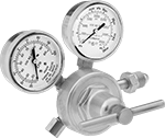
NPT Female Outlet × Female Inlet Two-Stage Valves with T-Handle | NPT Female Outlet × Male Inlet Two-Stage Valves with T-Handle | NPT Male Outlet × Male Inlet Two-Stage Valves with T-Handle |
 |  |  |
UNF Female Outlet x Female Inlet Two-Stage Valves with T-Handle | UNF Female Outlet x Male Inlet Two-Stage Valves with T-Handle | UNF Male Outlet × Female Inlet Two-Stage Valves with T-Handle |
Inlet | Outlet | Material | |||||||||||||
|---|---|---|---|---|---|---|---|---|---|---|---|---|---|---|---|
CGA No. | Location | Thread Direction | Pressure Gauge Reading Range, psi | Location | Thread Direction | Pressure Range, psi | Pressure Adjustment Method | Body | Seal | Diaphragm | Temp. Range, ° F | Each | |||
For Argon, Helium, and Nitrogen | |||||||||||||||
1/4 NPT Female Outlet × NGO Male Inlet | |||||||||||||||
| 580 | Side | Right Hand | 0 to 4,000 | Side | Right Hand | 0 to 250 | T-Handle | Brass | PTFE | Neoprene | -20 to 120 | 3687N122 | 0000000 | ||
| 580 | Side | Right Hand | 0 to 4,000 | Side | Right Hand | 0 to 250 | T-Handle | Brass | PTFE | Stainless Steel | -20 to 120 | 3687N126 | 000000 | ||
5/8"-18 UNF Female Outlet × NGO Male Inlet | |||||||||||||||
| 580 | Side | Right Hand | 0 to 4,000 | Side | Right Hand | 0 to 50 | T-Handle | Brass | PTFE | Neoprene | -20 to 120 | 3687N121 | 000000 | ||
| 580 | Side | Right Hand | 0 to 4,000 | Side | Right Hand | 0 to 50 | T-Handle | Brass | PTFE | Stainless Steel | -20 to 120 | 7897A22 | 000000 | ||
| 580 | Side | Right Hand | 0 to 4,000 | Side | Right Hand | 0 to 125 | T-Handle | Brass/Steel | PTFE | Rubber | -20 to 120 | 7897A16 | 000000 | ||
| 580 | Side | Right Hand | 0 to 4,000 | Side | Right Hand | 0 to 125 | T-Handle | Brass | PTFE | Stainless Steel | -20 to 120 | 7897A23 | 000000 | ||
For Carbon Dioxide | |||||||||||||||
1/4 NPT Female Outlet × NGO Female Inlet | |||||||||||||||
| 320 | Side | Right Hand | 0 to 4,000 | Side | Right Hand | 0 to 250 | T-Handle | Brass | PTFE | Neoprene | -20 to 120 | 3687N124 | 000000 | ||
| 320 | Side | Right Hand | 0 to 4,000 | Side | Right Hand | 0 to 250 | T-Handle | Brass | PTFE | Stainless Steel | -20 to 120 | 3687N129 | 000000 | ||
5/8"-18 UNF Female Outlet × NGO Female Inlet | |||||||||||||||
| 320 | Side | Right Hand | 0 to 4,000 | Side | Right Hand | 0 to 125 | T-Handle | Brass/Steel | PTFE | Rubber | -20 to 120 | 7897A17 | 000000 | ||
For Oxygen | |||||||||||||||
1/4 NPT Female Outlet × NGO Female Inlet | |||||||||||||||
| 540 | Side | Right Hand | 0 to 4,000 | Side | Right Hand | 0 to 250 | T-Handle | Brass | PTFE | Neoprene | -20 to 120 | 3687N12 | 000000 | ||
| 540 | Side | Right Hand | 0 to 4,000 | Side | Right Hand | 0 to 250 | T-Handle | Brass | PTFE | Stainless Steel | -20 to 120 | 7897A75 | 000000 | ||
9/16"-18 UNF Male Outlet × NGO Female Inlet | |||||||||||||||
| 540 | Side | Right Hand | 0 to 4,000 | Side | Right Hand | 0 to 50 | T-Handle | Brass | PTFE | Neoprene | -20 to 120 | 3687N119 | 000000 | ||
| 540 | Side | Right Hand | 0 to 4,000 | Side | Right Hand | 0 to 50 | T-Handle | Brass | PTFE | Stainless Steel | -20 to 120 | 3687N125 | 000000 | ||
| 540 | Side | Right Hand | 0 to 4,000 | Side | Right Hand | 0 to 125 | T-Handle | Brass/Steel | PTFE | Rubber | -20 to 120 | 7897A3 | 000000 | ||
| 540 | Side | Right Hand | 0 to 4,000 | Side | Right Hand | 0 to 125 | T-Handle | Brass | PTFE | Stainless Steel | -20 to 120 | 7897A74 | 000000 | ||
For Air | |||||||||||||||
1/4 NPT Male Outlet × NGO Male Inlet | |||||||||||||||
| 590 | Side | Left Hand | 0 to 4,000 | Side | Right Hand | 0 to 125 | T-Handle | Brass | PTFE | Stainless Steel | -20 to 120 | 3687N131 | 000000 | ||
| 590 | Side | Left Hand | 0 to 4,000 | Side | Right Hand | 0 to 250 | T-Handle | Brass | PTFE | Stainless Steel | -20 to 120 | 3687N132 | 000000 | ||
For Breathable Air | |||||||||||||||
1/4 NPT Female Outlet × NGO Female Inlet | |||||||||||||||
| 346 | Side | Right Hand | 0 to 4,000 | Side | Right Hand | 0 to 250 | T-Handle | Brass | PTFE | Stainless Steel | -20 to 120 | 3687N135 | 000000 | ||
Tank-Mount High-Pressure-Regulating Valves for Air and Inert Gas
 |  |
Female Outlet × Female Inlet Elbow With T-Handle | Female Outlet × Male Inlet Elbow With T-Handle |
Inlet | Outlet | Material | ||||||||||||||
|---|---|---|---|---|---|---|---|---|---|---|---|---|---|---|---|---|
CGA No. | Location | Thread Direction | Pressure Gauge Reading Range, psi | No. of Stages | For Tube OD | Location | Pressure Range, psi | Pressure Adjustment Method | Shape | Body | Seal | Temp. Range, ° F | Each | |||
NGO Female Inlet × Swagelok® Female Outlet | ||||||||||||||||
| 677 | Side | Left Hand | 0 to 7,500 | Single | 1/4" | Bottom | 300 to 4,500 | T-Handle | 90° Elbow | Brass | PCTFE | -20 to 120 | 6677A14 | 000000000 | ||
NGO Male Inlet × Swagelok® Female Outlet | ||||||||||||||||
| 580 | Side | Right Hand | 0 to 4,000 | Single | 1/4" | Bottom | 200 to 3,000 | T-Handle | 90° Elbow | Brass | PCTFE | -20 to 120 | 6677A13 | 000000 | ||
 |
Female Outlet × Female Inlet Straight With Knob |
Inlet | Outlet | Material | |||||||||||||||
|---|---|---|---|---|---|---|---|---|---|---|---|---|---|---|---|---|---|
CGA No. | Location | Thread Direction | Pressure Gauge Reading Range, psi | No. of Stages | For Tube OD | Location | Pressure Range, psi | Pressure Adjustment Method | Shape | Body | Seal | Diaphragm | Temp. Range, ° F | Each | |||
NGO Female Inlet × Swagelok® Female Outlet | |||||||||||||||||
| 540 | Side | Right Hand | 0 to 4,000 | Single | 1/4" | Side | 0 to 1,500 | Knob | Straight | Brass | PCTFE | Neoprene | -20 to 120 | 6677A17 | 0000000 | ||
| 540 | Side | Right Hand | 0 to 4,000 | Single | 1/4" | Side | 0 to 2,500 | Knob | Straight | Brass | PCTFE | Neoprene | -20 to 120 | 6677A18 | 000000 | ||
 |
Female Outlet × Male Inlet Straight With Knob |
Inlet | Outlet | Material | |||||||||||||||
|---|---|---|---|---|---|---|---|---|---|---|---|---|---|---|---|---|---|
CGA No. | Location | Thread Direction | Pressure Gauge Reading Range, psi | No. of Stages | For Tube OD | Location | Pressure Range, psi | Pressure Adjustment Method | Shape | Body | Seal | Diaphragm | Temp. Range, ° F | Each | |||
NGO Male Inlet × Swagelok® Female Outlet | |||||||||||||||||
| 590 | Side | Left Hand | 0 to 4,000 | Single | 1/4" | Side | 0 to 1,500 | Knob | Straight | Brass | PCTFE | Polyurethane Rubber | -20 to 120 | 6677A15 | 0000000 | ||
| 590 | Side | Left Hand | 0 to 4,000 | Single | 1/4" | Side | 0 to 2,500 | Knob | Straight | Brass | PCTFE | Polyurethane Rubber | -20 to 120 | 6677A16 | 000000 | ||
|
Female Outlet × Female Inlet Straight With Knob |
Inlet | Outlet | Material | |||||||||||||||
|---|---|---|---|---|---|---|---|---|---|---|---|---|---|---|---|---|---|
CGA No. | Location | Thread Direction | Pressure Gauge Reading Range, psi | No. of Stages | For Tube OD | Location | Pressure Range, psi | Pressure Adjustment Method | Shape | Body | Seal | Diaphragm | Temp. Range, ° F | Each | |||
NGO Female Inlet × Swagelok® Female Outlet | |||||||||||||||||
| 346 | Side | Right Hand | 0 to 4,000 | Single | 1/4" | Side | 0 to 1,500 | Knob | Straight | Brass | PCTFE | Polyurethane Rubber | -20 to 120 | 6677A19 | 0000000 | ||
| 346 | Side | Right Hand | 0 to 4,000 | Single | 1/4" | Side | 0 to 2,500 | Knob | Straight | Brass | PCTFE | Polyurethane Rubber | -20 to 120 | 6677A21 | 000000 | ||
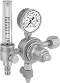
Easy-Read Tank-Mount Pressure-Regulating Valves with Flowmeter for Inert Gas
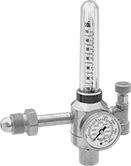 |
Male Inlet × Female Outlet With One Flowmeter |
Inlet | Outlet | Material | ||||||||||||||
|---|---|---|---|---|---|---|---|---|---|---|---|---|---|---|---|---|
CGA No. | Location | Thread Direction | Pressure Gauge Reading Range, psi | No. of Stages | Thread Size | Location | Thread Direction | Flow Range | No. of Flowmeters | Body | Seal | Diaphragm | Each | |||
UNF Female Outlet × NGO Male Inlet | ||||||||||||||||
| 580 | Side | Right Hand | 0 to 4,000 | Single | 5/8"-18 | Side | Right Hand | 0 scfh to 70 scfh | 1 | Brass | PTFE | Neoprene | 78595A43 | 0000000 | ||
|
Male Inlet × Female Outlet With One Flowmeter |
Inlet | Outlet | Material | ||||||||||||||
|---|---|---|---|---|---|---|---|---|---|---|---|---|---|---|---|---|
CGA No. | Location | Thread Direction | Pressure Gauge Reading Range, psi | No. of Stages | Thread Size | Location | Thread Direction | Flow Range | No. of Flowmeters | Body | Seal | Diaphragm | Each | |||
UNF Female Outlet × NGO Male Inlet | ||||||||||||||||
| 580 | Side | Right Hand | 0 to 3,000 | Single | 5/8"-18 | Side | Right Hand | 0 to 70 scfh (Argon), 0 to 70 scfh (Argon/Carbon Dioxide Blend) | 1 | Brass | PTFE | Neoprene | 78595A5 | 0000000 | ||
Inlet | Outlet | Material | ||||||||||||||
|---|---|---|---|---|---|---|---|---|---|---|---|---|---|---|---|---|
CGA No. | Location | Thread Direction | Pressure Gauge Reading Range, psi | No. of Stages | Thread Size | Location | Thread Direction | Flow Range | No. of Flowmeters | Body | Seal | Diaphragm | Each | |||
UNF Female Outlet × NGO Male Inlet | ||||||||||||||||
| 580 | Side | Right Hand | 0 to 3,000 | Two | 5/8"-18 | Side | Right Hand | 0 to 40 scfh (Argon), 0 to 40 scfh (Argon/Carbon Dioxide Blend), 0 to 150 scfh (Helium) | 1 | Brass | PTFE | Neoprene | 78595A495 | 0000000 | ||
|
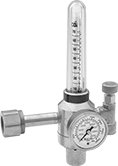
Male Inlet × Female Outlet With One Flowmeter |
Inlet | Outlet | Material | ||||||||||||||
|---|---|---|---|---|---|---|---|---|---|---|---|---|---|---|---|---|
CGA No. | Location | Thread Direction | Pressure Gauge Reading Range, psi | No. of Stages | Thread Size | Location | Thread Direction | Flow Range | No. of Flowmeters | Body | Seal | Diaphragm | Each | |||
UNF Female Outlet × NGO Male Inlet | ||||||||||||||||
| 580 | Side | Right Hand | 0 to 4,000 | Single | 5/8"-18 | Side | Right Hand | 0 to 60 scfh (Argon) 0 to 60 scfh (Argon/Carbon Dioxide Blend) 0 to 50 scfh (Carbon Dioxide) 0 to 160 scfh (Helium) | 1 | Brass | Buna-N | Brass | 78595A394 | 0000000 | ||
| 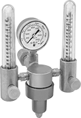 |
Male Inlet × Female Outlet With One Flowmeter | Male Inlet × Female Outlet With Two Flowmeters |
Inlet | Outlet | Material | ||||||||||||||
|---|---|---|---|---|---|---|---|---|---|---|---|---|---|---|---|---|
CGA No. | Location | Thread Direction | Pressure Gauge Reading Range, psi | No. of Stages | Thread Size | Location | Thread Direction | Flow Range | No. of Flowmeters | Body | Seal | Diaphragm | Each | |||
UNF Female Outlet × NGO Male Inlet | ||||||||||||||||
| 580 | Side | Right Hand | 0 to 3,000 | Two | 5/8"-18 | Side | Right Hand | 0 to 18 scfh (Argon), 0 to 50 scfh (Helium) | 1 | Brass | PTFE | Neoprene | 78595A492 | 0000000 | ||
| 580 | Side | Right Hand | 0 to 3,000 | Two | 5/8"-18 | Side | Right Hand | 0 to 65 scfh (Argon), 0 to 200 scfh (Helium) | 1 | Brass | PTFE | Neoprene | 78595A493 | 000000 | ||
| 580 | Side | Right Hand | 0 to 4,000 | Single | 5/8"-18 | Side | Right Hand | 0 to 45 scfh (Argon), 0 to 140 scfh (Helium) | 1 | Brass | PTFE | Neoprene | 78595A31 | 000000 | ||
| 580 | Side | Right Hand | 0 to 4,000 | Single | 5/8"-18 | Side | Right Hand | 0 to 45 scfh (Argon), 0 to 140 scfh (Helium) | 2 | Brass | PTFE | Neoprene | 7952A49 | 000000 | ||
 |
Female Inlet × Female Outlet With One Flowmeter |
Inlet | Outlet | Material | ||||||||||||||
|---|---|---|---|---|---|---|---|---|---|---|---|---|---|---|---|---|
CGA No. | Location | Thread Direction | Pressure Gauge Reading Range, psi | No. of Stages | Thread Size | Location | Thread Direction | Flow Range | No. of Flowmeters | Body | Seal | Diaphragm | Each | |||
UNF Female Outlet × NGO Female Inlet | ||||||||||||||||
| 320 | Side | Right Hand | 0 to 4,000 | Single | 5/8"-18 | Side | Right Hand | 0 scfh to 70 scfh | 1 | Brass | PTFE | Neoprene | 78595A46 | 0000000 | ||
|
Male Inlet × Female Outlet With One Flowmeter |
Inlet | Outlet | Material | ||||||||||||||
|---|---|---|---|---|---|---|---|---|---|---|---|---|---|---|---|---|
CGA No. | Location | Thread Direction | Pressure Gauge Reading Range, psi | No. of Stages | Thread Size | Location | Thread Direction | Flow Range | No. of Flowmeters | Body | Seal | Diaphragm | Each | |||
UNF Female Outlet × NGO Male Inlet | ||||||||||||||||
| 580 | Side | Right Hand | 0 to 4,000 | Single | 5/8"-18 | Side | Right Hand | 0 to 100 scfh (Helium), 0 to 140 scfh (Hydrogen) | 1 | Brass | PTFE | Neoprene | 78595A499 | 0000000 | ||
 |
Female Inlet × Male Outlet With One Flowmeter |
Inlet | Outlet | Material | ||||||||||||||
|---|---|---|---|---|---|---|---|---|---|---|---|---|---|---|---|---|
CGA No. | Location | Thread Direction | Pressure Gauge Reading Range, psi | No. of Stages | Thread Size | Location | Thread Direction | Flow Range | No. of Flowmeters | Body | Seal | Diaphragm | Each | |||
UNF Male Outlet × NGO Female Inlet | ||||||||||||||||
| 350 | Side | Left Hand | 0 to 3,000 | Single | 9/16"-18 | Side | Left Hand | 0 scfh to 40 scfh | 1 | Brass | PTFE | Neoprene | 78595A498 | 0000000 | ||
|
Male Inlet × Female Outlet With One Flowmeter |
Inlet | Outlet | Material | ||||||||||||||
|---|---|---|---|---|---|---|---|---|---|---|---|---|---|---|---|---|
CGA No. | Location | Thread Direction | Pressure Gauge Reading Range, psi | No. of Stages | Thread Size | Location | Thread Direction | Flow Range | No. of Flowmeters | Body | Seal | Diaphragm | Each | |||
UNF Female Outlet × NGO Male Inlet | ||||||||||||||||
| 580 | Side | Right Hand | 0 to 4,000 | Single | 5/8"-18 | Side | Right Hand | 0 scfh to 100 scfh | 1 | Brass | PTFE | Neoprene | 78595A35 | 0000000 | ||
Tank-Mount Pressure-Regulating Valves for Fuel Gases
 |  |  |  |
Male Outlet × Female Inlet Single-Stage Valve With T-Handle | Male Outlet × Female Inlet Single-Stage Valve With Knob | Male Outlet × Male Inlet Single-Stage Valve With T-Handle | Male Outlet × Male Inlet Single-Stage Valve With Knob |
Inlet | Outlet | Material | ||||||||||||||
|---|---|---|---|---|---|---|---|---|---|---|---|---|---|---|---|---|
CGA No. | Location | Thread Direction | Pressure Gauge Reading Range, psi | Thread Size | Location | Thread Direction | Pressure Range, psi | Pressure Adjustment Method | Body | Seal | Diaphragm | Temp. Range, ° F | Each | |||
For Acetylene | ||||||||||||||||
UNF Male Outlet × NGO Female Inlet | ||||||||||||||||
| 300 | Side | Right Hand | 0 to 400 | 9/16"-18 | Side | Left Hand | 0 to 15 | T-Handle | Brass | PTFE | Rubber | -20 to 120 | 7897A2 | 0000000 | ||
| 300 | Side | Right Hand | 0 to 400 | 9/16"-18 | Side | Left Hand | 0 to 15 | Knob | Brass/Steel | PTFE | Rubber | -20 to 120 | 7897A62 | 000000 | ||
UNF Male Outlet × NGO Male Inlet | ||||||||||||||||
| 510 | Side | Left Hand | 0 to 400 | 9/16"-18 | Side | Left Hand | 0 to 15 | T-Handle | Brass | PTFE | Rubber | -20 to 120 | 7897A7 | 000000 | ||
| 510 | Side | Left Hand | 0 to 400 | 9/16"-18 | Side | Left Hand | 0 to 15 | T-Handle | Brass | PTFE | Stainless Steel | -20 to 120 | 7897A53 | 000000 | ||
| 510 | Side | Left Hand | 0 to 400 | 9/16"-18 | Side | Left Hand | 0 to 15 | Knob | Brass/Steel | PTFE | Rubber | -20 to 120 | 7897A63 | 000000 | ||
For Hydrogen | ||||||||||||||||
UNF Male Outlet × NGO Female Inlet | ||||||||||||||||
| 350 | Side | Left Hand | 0 to 4,000 | 9/16"-18 | Side | Left Hand | 0 to 125 | T-Handle | Brass | PTFE | Rubber | -20 to 120 | 7897A5 | 000000 | ||
For Propane and Propylene | ||||||||||||||||
UNF Male Outlet × NGO Male Inlet | ||||||||||||||||
| 510 | Side | Left Hand | 0 to 400 | 9/16"-18 | Side | Left Hand | 0 to 50 | T-Handle | Brass | PTFE | Rubber | -20 to 120 | 7897A13 | 000000 | ||
| 510 | Side | Left Hand | 0 to 400 | 9/16"-18 | Side | Left Hand | 5 to 50 | Knob | Brass/Steel | PTFE | Rubber | -20 to 120 | 7897A66 | 000000 | ||
 |  |  |
Male Outlet × Female Inlet Two-Stage Valve With T-Handle | Male Outlet × Female Inlet Two-Stage Valve With Knob | Male Outlet × Male Inlet Two-Stage Valve With T-Handle |
Inlet | Outlet | Material | ||||||||||||||
|---|---|---|---|---|---|---|---|---|---|---|---|---|---|---|---|---|
CGA No. | Location | Thread Direction | Pressure Gauge Reading Range, psi | Thread Size | Location | Thread Direction | Pressure Range, psi | Pressure Adjustment Method | Body | Seal | Diaphragm | Temp. Range, ° F | Each | |||
For Acetylene | ||||||||||||||||
UNF Male Outlet × NGO Female Inlet | ||||||||||||||||
| 300 | Side | Right Hand | 0 to 400 | 9/16"-18 | Side | Left Hand | 0 to 15 | T-Handle | Brass/Steel | PTFE | Rubber | -20 to 120 | 7897A4 | 0000000 | ||
UNF Male Outlet × NGO Male Inlet | ||||||||||||||||
| 510 | Side | Left Hand | 0 to 400 | 9/16"-18 | Side | Left Hand | 0 to 15 | T-Handle | Brass/Steel | PTFE | Rubber | -20 to 120 | 7897A14 | 000000 | ||
For Hydrogen and Methane | ||||||||||||||||
UNF Male Outlet × NGO Female Inlet | ||||||||||||||||
| 350 | Side | Left Hand | 0 to 4,000 | 9/16"-18 | Side | Left Hand | 0 to 80 | Knob | Brass | Neoprene | Stainless Steel | -20 to 120 | 7897A35 | 000000 | ||
For Propane and Propylene | ||||||||||||||||
UNF Male Outlet × NGO Male Inlet | ||||||||||||||||
| 510 | Side | Left Hand | 0 to 400 | 9/16"-18 | Side | Left Hand | 0 to 50 | T-Handle | Brass/Steel | PTFE | Rubber | -20 to 120 | 7897A18 | 000000 | ||
High-Purity Tank-Mount Pressure-Regulating Valves for Inert Gas
 |  |
Swagelok® Female Outlet × NGO Male Inlet (Brass) | Swagelok® Female Outlet × NGO Male Inlet (Chrome-Plated Brass) |
Inlet | Outlet | ||||||||||||
|---|---|---|---|---|---|---|---|---|---|---|---|---|---|
CGA No. | Location | Thread Direction | Pressure Gauge Reading Range, psi | No. of Stages | For Tube OD | Location | Pressure Range, psi | Pressure Adjustment Method | Temp. Range, ° F | Each | |||
NGO Male Inlet × Swagelok® Female Outlet | |||||||||||||
Brass Body—316 Stainless Steel Diaphragm and PTFE Seal | |||||||||||||
| 580 | Side | Right Hand | 0 to 4,000 | Single | 1/4" | Side | 0 to 15 | Knob | -20 to 120 | 7951A14 | 0000000 | ||
| 580 | Side | Right Hand | 0 to 4,000 | Single | 1/4" | Side | 0 to 125 | Knob | -20 to 120 | 7951A16 | 000000 | ||
| 580 | Side | Right Hand | 0 to 4,000 | Single | 1/4" | Side | 0 to 500 | Knob | -20 to 120 | 7951A74 | 000000 | ||
| 580 | Side | Right Hand | 0 to 4,000 | Two | 1/4" | Side | 0 to 15 | Knob | -20 to 120 | 7951A24 | 000000 | ||
| 580 | Side | Right Hand | 0 to 4,000 | Two | 1/4" | Side | 0 to 50 | Knob | -20 to 120 | 7951A61 | 000000 | ||
| 580 | Side | Right Hand | 0 to 4,000 | Two | 1/4" | Side | 0 to 250 | Knob | -20 to 120 | 7951A75 | 000000 | ||
Chrome-Plated Brass Body—316 Stainless Steel Diaphragm and PTFE Seal | |||||||||||||
| 580 | Side | Right Hand | 0 to 4,000 | Two | 1/4" | Side | 0 to 50 | Knob | -20 to 120 | 7951A62 | 000000 | ||
| 580 | Side | Right Hand | 0 to 4,000 | Two | 1/4" | Side | 0 to 125 | Knob | -20 to 120 | 7951A28 | 000000 | ||
 |  |
Swagelok® Female Outlet × NGO Female Inlet (Brass) | Swagelok® Female Outlet × NGO Female Inlet (Chrome-Plated Brass) |
Inlet | Outlet | ||||||||||||
|---|---|---|---|---|---|---|---|---|---|---|---|---|---|
CGA No. | Location | Thread Direction | Pressure Gauge Reading Range, psi | No. of Stages | For Tube OD | Location | Pressure Range, psi | Pressure Adjustment Method | Temp. Range, ° F | Each | |||
NGO Female Inlet × Swagelok® Female Outlet | |||||||||||||
Brass Body—316 Stainless Steel Diaphragm and PTFE Seal | |||||||||||||
| 320 | Side | Right Hand | 0 to 4,000 | Single | 1/4" | Side | 0 to 15 | Knob | -20 to 120 | 7951A72 | 0000000 | ||
| 320 | Side | Right Hand | 0 to 4,000 | Single | 1/4" | Side | 0 to 125 | Knob | -20 to 120 | 7951A73 | 000000 | ||
| 320 | Side | Right Hand | 0 to 4,000 | Two | 1/4" | Side | 0 to 125 | Knob | -20 to 120 | 7951A69 | 000000 | ||
Chrome-Plated Brass Body—316 Stainless Steel Diaphragm and PTFE Seal | |||||||||||||
| 320 | Side | Right Hand | 0 to 4,000 | Single | 1/4" | Side | 0 to 15 | Knob | -20 to 120 | 7951A63 | 000000 | ||
| 320 | Side | Right Hand | 0 to 4,000 | Single | 1/4" | Side | 0 to 50 | Knob | -20 to 120 | 7951A34 | 000000 | ||
| 320 | Side | Right Hand | 0 to 4,000 | Two | 1/4" | Side | 0 to 15 | Knob | -20 to 120 | 7951A66 | 000000 | ||
| 320 | Side | Right Hand | 0 to 4,000 | Two | 1/4" | Side | 0 to 50 | Knob | -20 to 120 | 7951A67 | 000000 | ||
| 320 | Side | Right Hand | 0 to 4,000 | Two | 1/4" | Side | 0 to 125 | Knob | -20 to 120 | 7951A68 | 000000 | ||
Pressure-Regulating Valves for Fuel Gases
 |  |
With T-Handle | With Knob |
Inlet | Outlet | Lg. | ||||||||||||
|---|---|---|---|---|---|---|---|---|---|---|---|---|---|---|
For Use With | Pipe Size | Location | Max. Pressure, psi | Pipe Size | Location | Pressure Adjustment Method | Pressure Gauge Measurement Range, psi | Temp. Range, ° F | End-to-End | Port-to-Port | Each | |||
NPT Female | ||||||||||||||
Brass Body—Stainless Steel Diaphragm and Neoprene Seal | ||||||||||||||
| Acetylene | 1/4 | Side | 350 | 1/4 | Bottom, Side | Knob | 0 to 30 | -20 to 120 | 3.600" | 1.32" | 7864A14 | 0000000 | ||
| Hydrogen, Propane | 1/4 | Side | 500 | 1/4 | Bottom, Side | T-Handle | 0 to 60 | 0 to 120 | 2.400" | 1.01" | 7864A11 | 000000 | ||
| Hydrogen, Propane | 1/4 | Side | 500 | 1/4 | Bottom, Side | T-Handle | 0 to 200 | 0 to 120 | 2.400" | 1.01" | 7864A12 | 000000 | ||
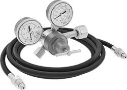
Tank-Mount Pressure-Regulating Valves with Flowmeter for Inert Gas
 | 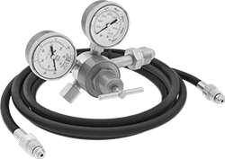 |
Female Outlet × Male Inlet | Female Outlet × Male Inlet with Hose |
Inlet | Outlet | Material | ||||||||||||||||
|---|---|---|---|---|---|---|---|---|---|---|---|---|---|---|---|---|---|---|
CGA No. | Location | Thread Direction | Pressure Gauge Reading Range, psi | No. of Stages | Thread Size | Location | Thread Direction | Flow Range, scfh | Flow Gauge Included | Body | Seal | Diaphragm | Includes | Temp. Range, ° F | Each | |||
UNF Female Outlet × NGO Male Inlet | ||||||||||||||||||
| 580 | Side | Right Hand | 0 to 4,000 | Single | 5/8"-18 | Side | Right Hand | 0 to 60 | Yes | Brass | PTFE | Neoprene | — | -20 to 120 | 7997A65 | 0000000 | ||
| 580 | Side | Right Hand | 0 to 4,000 | Single | 5/8"-18 | Side | Right Hand | 0 to 60 | Yes | Brass | PTFE | Neoprene | 10-ft. long, 3/16" dia. hose with 5/8"-18 male fittings on both ends | -20 to 120 | 7997A67 | 000000 | ||
| 580 | Side | Right Hand | 0 to 4,000 | Single | 5/8"-18 | Side | Right Hand | 0 to 100 | Yes | Brass | PTFE | Neoprene | — | -20 to 120 | 7997A52 | 000000 | ||
 |  |
Female Outlet × Female Inlet | Female Outlet × Female Inlet with Hose |
Inlet | Outlet | Material | ||||||||||||||||
|---|---|---|---|---|---|---|---|---|---|---|---|---|---|---|---|---|---|---|
CGA No. | Location | Thread Direction | Pressure Gauge Reading Range, psi | No. of Stages | Thread Size | Location | Thread Direction | Flow Range, scfh | Flow Gauge Included | Body | Seal | Diaphragm | Includes | Temp. Range, ° F | Each | |||
UNF Female Outlet × NGO Female Inlet | ||||||||||||||||||
| 320 | Side | Right Hand | 0 to 4,000 | Single | 5/8"-18 | Side | Right Hand | 0 to 60 | Yes | Brass | PTFE | Neoprene | — | -20 to 120 | 7997A66 | 0000000 | ||
| 320 | Side | Right Hand | 0 to 4,000 | Single | 5/8"-18 | Side | Right Hand | 0 to 60 | Yes | Brass | PTFE | Neoprene | 10-ft. long, 3/16" dia. hose with 5/8"-18 male fittings on both ends | -20 to 120 | 7997A68 | 000000 | ||
| 320 | Side | Right Hand | 0 to 4,000 | Single | 5/8"-18 | Side | Right Hand | 0 to 100 | Yes | Brass | PTFE | Neoprene | — | -20 to 120 | 7997A51 | 000000 | ||
High-Purity Tank-Mount Pressure-Regulating Valves for Fuel Gases
 |
Single Stage |
 |
Two Stage |
Inlet | Outlet | |||||||||||||
|---|---|---|---|---|---|---|---|---|---|---|---|---|---|---|
CGA No. | Location | Thread Direction | Pressure Gauge Reading Range, psi | No. of Stages | For Tube OD | Location | Pressure Range, psi | Pressure Adjustment Method | For Use With | Temp. Range, ° F | Each | |||
NGO Female Inlet × Swagelok® Female Outlet | ||||||||||||||
Brass Body—316 Stainless Steel Diaphragm and PTFE Seal with Relief Valve | ||||||||||||||
| 350 | Side | Left Hand | 0 to 4,000 | Single | 1/4" | Side | 0 to 15 | Knob | Hydrogen, Methane | -20 to 120 | 7951A17 | 0000000 | ||
| 350 | Side | Left Hand | 0 to 4,000 | Two | 1/4" | Side | 0 to 125 | Knob | Hydrogen, Methane | -20 to 120 | 7951A29 | 000000 | ||
| 350 | Side | Left Hand | 0 to 4,000 | Two | 1/4" | Side | 0 to 500 | Knob | Hydrogen, Methane | -20 to 120 | 7951A71 | 000000 | ||
Chrome-Plated Brass Body—316 Stainless Steel Diaphragm and PTFE Seal with Relief Valve | ||||||||||||||
| 350 | Side | Left Hand | 0 to 4,000 | Single | 1/4" | Side | 0 to 125 | Knob | Hydrogen, Methane | -20 to 120 | 7951A31 | 000000 | ||
| 350 | Side | Left Hand | 0 to 4,000 | Two | 1/4" | Side | 0 to 15 | Knob | Hydrogen, Methane | -20 to 120 | 7951A32 | 000000 | ||
Tank-Mount Pressure-Regulating Valves for Cryogenic Cylinders
 |
Inlet | Outlet | |||||||||||||
|---|---|---|---|---|---|---|---|---|---|---|---|---|---|---|
For Use With | CGA No. | Location | Thread Direction | No. of Stages | Thread Size | Location | Thread Direction | Pressure Range, psi | Pressure Adjustment Method | Temp. Range, ° F | Each | |||
UNF Male Outlet × NGO Female Inlet | ||||||||||||||
Brass Body—Stainless Steel Diaphragm and PTFE Seal | ||||||||||||||
| Carbon Dioxide | 320 | Side | Right Hand | Single | 9/16"-18 | Bottom | Right Hand | 0 to 350 | T-Handle | -20 to 120 | 7897A83 | 0000000 | ||
| Oxygen | 540 | Side | Right Hand | Single | 9/16"-18 | Bottom | Right Hand | 0 to 125 | T-Handle | -20 to 120 | 7897A84 | 000000 | ||
UNF Male Outlet × NGO Male Inlet | ||||||||||||||
Brass Body—Stainless Steel Diaphragm and PTFE Seal | ||||||||||||||
| Nitrogen, Argon | 580 | Side | Right Hand | Single | 9/16"-18 | Bottom | Right Hand | 0 to 350 | T-Handle | -20 to 120 | 7897A87 | 000000 | ||
Tank-Mount Pressure-Regulating Valves for Moisture Removal
 |
Inlet | Outlet | |||||||||||||||
|---|---|---|---|---|---|---|---|---|---|---|---|---|---|---|---|---|
CGA No. | Location | Thread Direction | Pressure Gauge Reading Range, psi | No. of Stages | For Tube OD | Location | Thread Direction | Purging Flow Range, ft³/hr | Brazing Flow Range, ft³/hr | Testing Pressure Range, psi | For Use With | Temp. Range, ° F | Each | |||
NGO Male Inlet × 45° Flared UN/UNF (SAE 45°) Male Outlet with 7/16"-20 End | ||||||||||||||||
Brass Body—PTFE Seal | ||||||||||||||||
| 580 | Side | Right Hand | 0 to 3,000 | Single | 1/4" | Side | Right Hand | 25 to 35 | 3 to 6 | 0 to 500 | Nitrogen | 32 to 120 | 66325A52 | 0000000 | ||
