


Pipe Size Pipe Size | Show |
|---|
Thread Type Thread Type |
|---|
Connection Style Connection Style |
|---|
 |
| Threaded |
 |
| Socket Connect |
For Use With For Use With |
|---|
For Pipe Material For Pipe Material |
|---|
|
Maximum Pressure Maximum Pressure |
|---|
Connection Type Connection Type |
|---|
| Pipe | |


RoHS (Restriction of Hazardous Substances) RoHS (Restriction ofHazardous Substances) |
|---|
|
DFARS (Defense Acquisition Regulations Supplement) DFARS (Defense AcquisitionRegulations Supplement) |
|---|
Finish Finish |
|---|
|
REACH (Registration, Evaluation, Authorization and Restriction of Chemicals) REACH (Registration,Evaluation, Authorization and Restriction of Chemicals) |
|---|
|
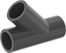
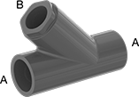
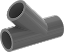
Flow Pattern Flow Pattern |
|---|
| Y-Pattern |
Color Color |
|---|
| White | Black | ||
| Dark Gray | Light Gray | ||
| Clear | |||
Maximum Steam Pressure Maximum Steam Pressure |
|---|
|
System of Measurement System of Measurement |
|---|
|
How to Identify and Measure Fittings
Pipe size is an industry designation, not the actual size. View information about how to measure threaded and unthreaded pipe and pipe fittings.
More
About Backflow-Prevention Valves
More
About Strainers and Selecting Screen Size
More
About On/Off Valves
More
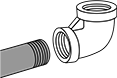
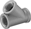
Low-Pressure Stainless Steel Threaded Pipe Fittings
Use these fittings in a low-pressure pipe line. 304 stainless steel fittings have very good corrosion resistance. 316 stainless steel fittings have excellent corrosion resistance.
![]() For technical drawings and 3-D models, click on a part number.
For technical drawings and 3-D models, click on a part number.
- For Use With: Air, Natural Gas, Oil, Steam, Water
- Pressure Class: 150
- Fabrication: Heat Treated
- Specifications Met: ASTM A351
- Pipe Nipples and Pipe: Use Schedule 40 stainless steel
- Flanges: Use Class 150 stainless steel
Low-Pressure Iron and Steel Threaded Pipe Fittings
Use these fittings for low-pressure applications in noncorrosive environments.
![]() For technical drawings and 3-D models, click on a part number.
For technical drawings and 3-D models, click on a part number.
- For Use With: Air, Steam, Oil, Water, Natural Gas
- Pressure Class: 150
- Specifications Met: ASME B16.3, UL Listed, ASME B1.20.1
- Pipe Nipples and Pipe: Use Schedule 40 steel
| Pipe Size | Max. Pressure | Max. Steam Pressure | Material | Each | |
NPT Female | |||||
|---|---|---|---|---|---|
| 1 | 150 psi @ 72° F | 150 psi @ 350° F | Black-Coated Iron | 000000000 | 000000 |
Low-Pressure Galvanized Iron and Steel Threaded Pipe Fittings
The galvanized finish on these fittings provides fair corrosion resistance. Fittings are for use in low-pressure applications.
![]() For technical drawings and 3-D models, click on a part number.
For technical drawings and 3-D models, click on a part number.
- Pressure Class: 150
- For Use With: Air, Steam, Oil, Water, Natural Gas
- Specifications Met: ASTM A197, UL Listed, ASME B16.3, ASME B1.20.1
- Pipe Nipples and Pipe: Use Schedule 40 galvanized steel
- Flanges: Use Class 150 galvanized steel
| Pipe Size | Max. Pressure | Max. Steam Pressure | Material | Each | |
NPT Female | |||||
|---|---|---|---|---|---|
| 1 | 150 psi @ 72° F | 150 psi @ 350° F | Galvanized Iron | 00000000 | 000000 |
Low-Pressure Brass and Bronze Threaded Pipe Fittings
Use these fittings in low-pressure flow applications. They have good corrosion resistance. Fittings rated for use with drinking water meet NSF/ANSI 61 safety standards.
![]() For technical drawings and 3-D models, click on a part number.
For technical drawings and 3-D models, click on a part number.
- For Use With: Air, Drinking Water, Natural Gas, Oil
- Pressure Class : 125
- Specifications Met: ASME B1.20.1, ASME B16.15, NSF/ANSI 61
- Pipe Nipples and Pipe: Use Schedule 40 brass
- Flanges: Use Class 150 brass
| Pipe Size | Max. Pressure | Material | Each | |
NPT Female | ||||
|---|---|---|---|---|
| 1 | 200 psi @ 72° F | Brass | 00000000 | 0000000 |
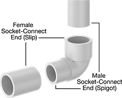
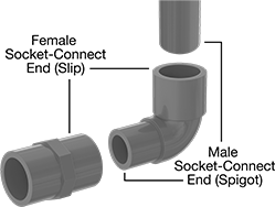
Standard-Wall Plastic Pipe Fittings for Water
Connect these fittings to Schedule 40 plastic pipe–they are the industry standard for residential and commercial low-pressure plumbing and water supply applications. They are plastic for good corrosion resistance.
Fittings for drinking water meet NSF/ANSI Standard 61.
Attach socket-connect ends to unthreaded pipe or another socket-connect fitting with a PVC primer and cement (also known as solvent weld).
Fittings that meet ASTM D1784, ASTM D1785, and ASTM D4066 adhere to specifications and testing requirements for material quality.
Note: For fittings that are not rated for pressure, you can use the pressure rating of the plastic pipe as a reference. Threaded fittings are limited to 50% of the rated pressure of the pipe.
Warning: Never use plastic pipe fittings and pipe with compressed air or gas.
![]() For technical drawings and 3-D models, click on a part number.
For technical drawings and 3-D models, click on a part number.
- For Use With: Drinking Water, Water
- Maximum Temperature: 140° F
- Specifications Met: ASTM D1784, NSF/ANSI 61
- Pipe Nipples and Pipe: Use Schedule 40 PVC Plastic
- Flanges: Use Schedule 40 PVC Plastic
| Pipe Size | Socket Depth | Material | Color | Each | |
| 1 | 1 1/32" | PVC Plastic | White | 00000000 | 00000 |
- For Use With: Drinking Water, Water
- Maximum Temperature: 140° F
- Specifications Met: ASTM D1784, NSF/ANSI 61
- Pipe Nipples and Pipe: Use Schedule 40 PVC Plastic
- Flanges: Use Schedule 40 PVC Plastic
Thick-Wall Plastic Pipe Fittings for Water
Connect these fittings to Schedule 80 pipe–they have thicker, stronger walls than standard-wall fittings so they can handle heavy duty industrial plumbing and water supply applications, such as water processing, waste water treatment, and irrigation. Fittings are plastic for good corrosion resistance. They meet ASTM specifications and testing requirements for material quality.
Fittings for drinking water meet NSF/ANSI Standard 61.
Attach socket-connect ends to unthreaded pipe or another socket-connect fitting with a PVC primer and cement (also known as solvent weld).
Note: For fittings that are not rated for pressure, you can use the pressure rating of the plastic pipe as a reference. Threaded fittings are limited to 50% of the rated pressure of the pipe.
Warning: Never use plastic pipe fittings and pipe with compressed air or gas.
![]() For technical drawings and 3-D models, click on a part number.
For technical drawings and 3-D models, click on a part number.
- For Use With: Drinking Water, Water
- Maximum Temperature: 140° F
- Specifications Met: ASTM D1784, NSF/ANSI 61
- Pipe Nipples and Pipe: Use Schedule 80 PVC Plastic
- Flanges: Use Class 150 PVC Plastic
| Pipe Size | Socket Depth | Material | Color | Each | |
| 1 | 1 1/8" | PVC Plastic | Dark Gray | 00000000 | 000000 |
- For Use With: Drinking Water, Water
- Maximum Temperature: 140° F
- Specifications Met: ASTM D1784, NSF/ANSI 61
- Pipe Nipples and Pipe: Use Schedule 80 PVC Plastic
- Flanges: Use Class 150 PVC Plastic
CPVC Pipe Fittings for Hot Water
Made of CPVC, these fittings can handle high temperatures up to 200° F. They have thick, strong walls to handle heavy duty industrial plumbing and water supply applications, such as water processing and waste water treatment. They also have good corrosion resistance. These fittings are comparable to Corzan. Some meet ASTM D1784 specifications and testing requirements for material quality.
Fittings for drinking water meet NSF/ANSI Standard 61.
Note: For fittings that are not rated for pressure, you can use the pressure rating of the plastic pipe as a reference. Threaded fittings are limited to 50% of the rated pressure of the pipe.
Warning: Never use plastic pipe fittings and pipe with compressed air or gas.
![]() For technical drawings and 3-D models, click on a part number.
For technical drawings and 3-D models, click on a part number.
- For Use With: Acetic Acid (10%), Calcium Chloride, Deionized Water, Drinking Water, Hydrochloric Acid (25%), Phosphoric Acid (85%), Salt Water, Sodium Hydroxide (50%), Sulfuric Acid (75%), Water
- Maximum Temperature: 200° F
- Specifications Met: ASTM D1784, NSF/ANSI 61
- Pipe Nipples and Pipe: Use Schedule 80 CPVC Plastic
- Flanges: Use Class 150 CPVC Plastic
Attach socket-connect ends to unthreaded pipe or another socket-connect fitting with a CPVC primer and cement (also known as solvent weld).
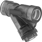
PVC Y-Strainers
- For Use With:
Dark Gray: Water and Diesel Fuel
Clear: Water - Max. Pressure: 150 psi @ 70° F
- Temp. Range:
Dark Gray: 40° to 140° F
Clear: 40° to 120° F
PVC construction is lightweight and provides excellent corrosion resistance. Install them prior to valves, pumps, and nozzles to catch debris in your pipeline and protect sensitive equipment. Strainers have a threaded drain with a hex cap or plug that provides access to the screen without disconnecting your line.
Clear strainers allow you to monitor debris collecting in the screen.
Strainers with socket-connect pipe connections attach to unthreaded pipe with cement for a permanent, leak-tight connection.
Strainers with two union end connections come with two socket-connect pipe connections and two threaded pipe connections; union end connections allow for easy access to your pipeline.
![]() For technical drawings and 3-D models, click on a part number.
For technical drawings and 3-D models, click on a part number.
Strainers | Replacement Screens | Replacement Caps | Replacement Gaskets | |||||||||||||
|---|---|---|---|---|---|---|---|---|---|---|---|---|---|---|---|---|
| Pipe Size | Thread Type | Lg. | Ht. | For Fitting Schedule | For Pipe Schedule | Features | Choose a Screen Mesh Size | Choose a Screen Opening Size | Each | Each | Each | Each | ||||
Dark Gray Strainer with PVC Plastic Screen | ||||||||||||||||
| 1 | NPT | 5 3/16" | 4 5/8" | 80 | 80 | Threaded Drain with Hex Cap | __ | 0000000 | 0000000 | 0000000 | 000000 | 0000000 | 000000 | 0000000 | 000000 | |
Clear Strainer with 316 Stainless Steel Screen | ||||||||||||||||
| 1 | NPT | 5 3/16" | 4 5/8" | __ | __ | Threaded Drain with Plug | __ | 0000000 | 000000 | 0000000 | 000000 | 000000 | 00 | 000000 | 00 | |
Strainers | Replacement Screens | Replacement Caps | Replacement Gaskets | ||||||||||||
|---|---|---|---|---|---|---|---|---|---|---|---|---|---|---|---|
| Pipe Size | Socket Connect Type | Lg. | Ht. | For Fitting Schedule | For Pipe Schedule | Features | Choose a Screen Opening Size | Each | Each | Each | Each | ||||
Dark Gray Strainer with PVC Plastic Screen | |||||||||||||||
| 1 | Cement | 5 3/16" | 4 5/8" | 80 | 80 | Threaded Drain with Hex Cap | 0000000 | 0000000 | 0000000 | 000000 | 0000000 | 000000 | 0000000 | 000000 | |
Strainers | |||||||||||
|---|---|---|---|---|---|---|---|---|---|---|---|
Threaded Pipe Connections | Socket-Connect Pipe Connections | Replacement Screens | |||||||||
| Pipe Size | Thread Type | Pipe Size | Type | Lg. | Ht. | Features | Choose a Screen Mesh Size | Each | Each | ||
Clear Strainer with PVC Plastic Screen | |||||||||||
| 1 | NPT | 1 | Cement | 8 13/16" | 5 3/4" | Threaded Drain with Plug, Two Union End Connections | 00000000 | 000000 | 00000000 | 000000 | |
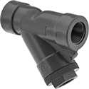
Polypropylene Y-Strainers
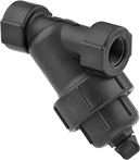
- Max. Pressure for Water: See Table
- Temp. Range: -20° to 150° F
These irrigation polypropylene strainers have excellent corrosion resistance and are lightweight. Install them in your pipeline to trap debris and prevent damage to valves, pumps, nozzles, and other sensitive equipment. They have a threaded drain with a plug that provides access to the screen without disconnecting your line.
![]() For technical drawings and 3-D models, click on a part number.
For technical drawings and 3-D models, click on a part number.
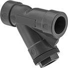
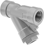
CPVC Y-Strainers
- Max. Pressure for Water and Diesel Fuel: 150 psi @ 70° F
- Temp. Range: 40° to 190° F
Made of CPVC, these lightweight strainers have excellent corrosion resistance and withstand higher temperatures than all of our other plastic Y-strainers. They trap debris in your pipeline before it can enter sensitive equipment such as valves, pumps, and nozzles. Strainers have a threaded drain with a hex cap that provides access to the screen without disconnecting your line.
Strainers with socket-connect pipe connections attach to unthreaded pipe with cement for a permanent, leak-tight connection.
![]() For technical drawings and 3-D models, click on a part number.
For technical drawings and 3-D models, click on a part number.
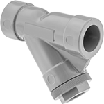
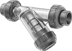
High-Capacity Plastic Y-Strainers
- Max. Pressure for Water: 150 psi @ 70° F
- Temp. Range: 40° to 140° F
A wide two-piece body holds more debris than other plastic Y-strainers. The body comes apart for easy cleaning without disconnecting your line. Strainers are made of lightweight plastic for excellent corrosion resistance. Install them in your pipeline to prevent damage to valves, pumps, nozzles, and other sensitive equipment.
Strainers that have a threaded drain with plug provide easy access to the screen.
Acetal strainers have a ball valve to control flow while cleaning.
![]() For technical drawings and 3-D models, click on a part number.
For technical drawings and 3-D models, click on a part number.
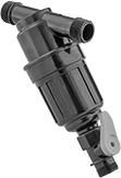
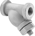
Low-Pressure Bronze Y-Strainers
- Max. Pressure for Water, Oil, Inert Gas, and Diesel Fuel: 200 psi @ 70° F
Max. Pressure for Steam: 125 psi @ 400° F - Temp. Range: -20° to 400° F
Install these strainers prior to valves, pumps, and nozzles to catch debris in your pipeline and protect sensitive equipment. They are designed for low-pressure applications. Strainers have a threaded drain with a plug that provides access to the screen without disconnecting your line. They are bronze for good corrosion resistance.
![]() For technical drawings and 3-D models, click on a part number.
For technical drawings and 3-D models, click on a part number.
Strainers | Replacement Screens | ||||||||||||
|---|---|---|---|---|---|---|---|---|---|---|---|---|---|
| Pipe Size | Thread Type | Lg. | Ht. | Plug Pipe Size | Screen Material | Screen OD | Screen Lg. | Choose a Screen Mesh Size | Choose a Screen Opening Size | Each | Each | ||
With Mesh Screen | |||||||||||||
| 1 | NPT | 4 1/2" | 4 1/2" | 1/2 | 304 Stainless Steel | 1 9/64" | 2 43/64" | 20 | __ | 00000000 | 000000 | 000000000 | 000000 |
| 1 | NPT | 4 1/2" | 4 1/2" | 1/2 | 304 Stainless Steel | 1 9/64" | 2 43/64" | __ | 00000000 | 00000 | 00000000 | 00000 | |
With Perforated Screen | |||||||||||||
| 1 | NPT | 4 1/2" | 4 1/2" | 1/2 | 304 Stainless Steel | 1 1/8" | 2 11/16" | __ | 000000000 | 00000 | 000000000 | 00000 | |
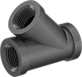
Medium-Pressure Bronze and Brass Y-Strainers
- Max. Pressure: See Table
- Max. Steam Pressure:
Brass: Not Rated
Bronze: 235 psi @ 400° F - Temp. Range:
Brass: 35° to 350° F
Bronze: -20° to 400° F
Strainers catch debris in your pipeline, preventing damage to valves, pumps, nozzles, and other sensitive equipment. They are designed for medium-pressure applications. Strainers have a threaded drain with a plug that provides access to the screen without disconnecting your line. They have good corrosion resistance.
Strainers with magnetic plug attract and catch ferrous particles.
Strainers for use with drinking water meet NSF/ANSI 61 safety standards for drinking water systems.
![]() For technical drawings and 3-D models, click on a part number.
For technical drawings and 3-D models, click on a part number.
Strainers | Replacement Screens | |||||||||||
|---|---|---|---|---|---|---|---|---|---|---|---|---|
| Pipe Size | Thread Type | Max. Pressure | Lg. | Ht. | Plug Pipe Size | Material | Screen Material | Choose a Screen Mesh Size | Each | Each | ||
For Use With Drinking Water—NSF/ANSI 61 | ||||||||||||
| 1 | NPT | 400 psi @ 70° F | 3 3/4" | 3 3/4" | 1/2 | Brass | 304 Stainless Steel | 20 | 0000000 | 0000000 | 0000000 | 000000 |
For Use With Water, Oil, Inert Gas, and Steam | ||||||||||||
| 1 | NPT | 400 psi @ 150° F | 4 1/8" | 4 1/16" | 1/4 | Bronze | 304 Stainless Steel | 0000000 | 000000 | 0000000 | 00000 | |
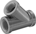
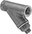
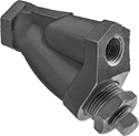
Low-Pressure Iron Y-Strainers
A rugged iron body provides excellent strength and durability. Strainers prevent damage to valves, pumps, nozzles, and other sensitive equipment by catching debris in your pipeline. They are designed for low-pressure applications. Strainers are for use in noncorrosive environments. They have a threaded drain with a plug that provides access to the screen without disconnecting your line.
![]() For technical drawings and 3-D models, click on a part number.
For technical drawings and 3-D models, click on a part number.
Strainers | Replacement Screens | |||||||||
|---|---|---|---|---|---|---|---|---|---|---|
| Pipe Size | Lg. | Ht. | Plug Pipe Size | Screen Material | Choose a Screen Mesh Size | Choose a Screen Opening Size | Each | Each | ||
With Mesh Screen | ||||||||||
| 1 | 4 7/8" | 5 3/8" | 3/4 | 304 Stainless Steel | 20 | __ | 0000000 | 000000 | 00000000 | 000000 |
With Mesh and Perforated Screen | ||||||||||
| 1 | 4 7/8" | 5 3/8" | 3/4 | 304 Stainless Steel | __ | 0000000 | 00000 | 0000000 | 00000 | |
With Perforated Screen | ||||||||||
| 1 | 4 7/8" | 5 3/8" | 3/4 | 304 Stainless Steel | __ | 0000000 | 00000 | 0000000 | 00000 | |
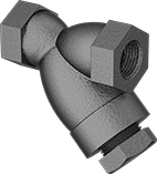
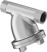
Medium-Pressure Iron and Steel Y-Strainers

- Max. Pressure for Water, Oil, and Inert Gas:
Iron: 600 psi @ 100° F
Steel: 700 psi @ 100° F
Max. Pressure for Steam:
Iron: 450 psi @ 650° F
Steel: 300 psi @ 400° F - Temp. Range:
Iron: -20° to 650° F
Steel: -20° to 400° F
Made of rugged iron or steel, these strainers provide excellent strength and durability. Install them prior to valves, pumps, and nozzles to protect sensitive equipment from damage caused by debris. They are designed for medium-pressure applications. Strainers are for use in noncorrosive environments. They have a threaded drain with a plug that provides access to the screen without disconnecting your line.
![]() For technical drawings and 3-D models, click on a part number.
For technical drawings and 3-D models, click on a part number.
Strainers | Replacement Screens | ||||||||||||
|---|---|---|---|---|---|---|---|---|---|---|---|---|---|
| Pipe Size | Thread Type | Lg. | Ht. | Plug Pipe Size | Material | Screen Material | Screen OD | Screen Lg. | Choose a Screen Opening Size | Each | Each | ||
With Perforated Screen | |||||||||||||
| 1 | NPT | 3 9/16" | 3 5/8" | 1/2 | Steel | 304 Stainless Steel | 1 3/16" | 2" | 0000000 | 000000 | 0000000 | 000000 | |
| 1 | NPT | 4 7/8" | 5 3/8" | 3/4 | Iron | 304 Stainless Steel | 1 1/4" | 3 7/8" | 000000 | 000000 | 0000000 | 00000 | |
High-Temperature High-Pressure Steel Y-Strainers
- Max. Pressure for Water, Oil, and Inert Gas: 1,400 psi @ 100° F
Max. Pressure for Steam: 600 psi @ 800° F - Temp. Range: -20° to 800° F
With a higher temperature rating than other strainers, these can handle applications reaching 800° F. Install them prior to valves, pumps, and nozzles to catch debris in your pipeline and protect sensitive equipment. Strainers are designed for high-pressure applications. They are steel for excellent strength and durability. Strainers are for use in noncorrosive environments. They have a threaded drain with a plug that provides access to the screen without disconnecting your line.
![]() For technical drawings and 3-D models, click on a part number.
For technical drawings and 3-D models, click on a part number.
High-Pressure Steel Y-Strainers
- Maximum Pressure for Water, Oil, and Inert Gas: 3,700psi @ 100° F
- Temperature Range: 0° to 450° F
Prevent debris from entering valves, pumps, nozzles, and other sensitive equipment in high-pressure applications. Strainers are steel, which provides excellent strength and durability. They are for use in noncorrosive environments. All have a bolt-on drain cover that provides access to the screen without disconnecting your line.
![]() For technical drawings and 3-D models, click on a part number.
For technical drawings and 3-D models, click on a part number.
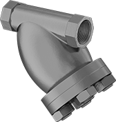
Medium-Pressure Stainless Steel Y-Strainers
- Max. Pressure for Water, Oil, Inert Gas, Natural Gas, and Diesel Fuel: 1,400 psi @ 70° F
Max. Pressure for Steam: 600 psi @ 1125° F - Temp. Range: 35° to 1125° F
316 stainless steel gives these strainers excellent corrosion resistance. Use them in medium-pressure applications to capture debris in your pipeline and protect sensitive equipment. Strainers have a threaded drain with a plug that provides access to the screen without disconnecting your line.
![]() For technical drawings and 3-D models, click on a part number.
For technical drawings and 3-D models, click on a part number.
Strainers | Replacement Screens | |||||||||||||
|---|---|---|---|---|---|---|---|---|---|---|---|---|---|---|
| Pipe Size | Thread Type | Lg. | Ht. | Plug Pipe Size | Screen Material | Screen Top OD | Screen Bottom OD | Screen Lg. | Choose a Screen Mesh Size | Choose a Screen Opening Size | Each | Each | ||
With Mesh and Perforated Screen | ||||||||||||||
| 1 | NPT | 5" | 6 1/2" | 3/4 | 304 Stainless Steel | 1 3/8" | 1 5/8" | 3 1/16" | __ | 0000000 | 0000000 | 0000000 | 000000 | |
With Perforated Screen | ||||||||||||||
| 1 | NPT | 5" | 6 1/2" | 3/4 | 304 Stainless Steel | 1 3/8" | 1 5/8" | 3 1/16" | __ | 00000000 | 000000 | 00000000 | 00000 | |
High-Pressure Stainless Steel Y-Strainers
- Maximum Pressure for Water, Oil, and Diesel Fuel: 3,600psi @ 100° F
- Temperature Range: 0° to 450° F
Built to withstand high-pressure applications in corrosive environments, these strainers are 316 stainless steel. They act as a safeguard against damage to valves, pumps, and nozzles by trapping debris in your pipeline. All have a bolt-on drain cover that provides access to the screen without disconnecting your line.
![]() For technical drawings and 3-D models, click on a part number.
For technical drawings and 3-D models, click on a part number.
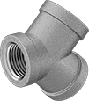
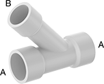
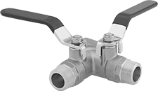
Dual Shut-Off Threaded Diverting Valves
 Female x Male x Male | 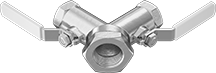 Female x Female x Female |
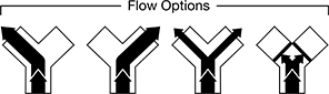 |
- Valve Type: Ball
- For Use With:
NPT Female × NPT Female × NPT Female: Air, Water
NPT Female × NPT Male × NPT Male: Air, Argon, Helium, Krypton, Neon, Oil, Water, Xenon - Seal Material: PTFE Plastic
Control flow in two directions from a single source—these valves have two handles for independent operation of each outlet. They can direct flow from the center-port inlet to one side-port outlet at full capacity, direct flow to both side-port outlets simultaneously at reduced capacity, or shut off flow to both outlet ports completely. Valves are standard port, so they slightly restrict flow.
![]() For technical drawings and 3-D models, click on a part number.
For technical drawings and 3-D models, click on a part number.
| Inlet Pipe Size | Outlet Pipe Sizes | Flow Pattern | Max. Pressure | Temp. Range, °F | Vacuum Rating, in. of Hg | End-to-End Lg. | Each | |
Brass Body | ||||||||
|---|---|---|---|---|---|---|---|---|
NPT Female × NPT Male × NPT Male | ||||||||
| 1 | 3/4 × 3/4 | Y-Pattern | 600 psi @ 200° F | -40° to 365° | 29 | 3 1/4" | 0000000 | 000000 |
Bronze Body | ||||||||
NPT Female × NPT Female × NPT Female | ||||||||
| 1 | 3/4 × 3/4 | Y-Pattern | 550 psi @ 150° F | Not Rated | 29 | 3 7/16" | 0000000 | 000000 |
High-Flow Threaded Check Valves
To achieve the maximum possible flow, internal components are designed to reduce flow resistance. These valves open to allow flow in one direction and close when flow stops or reverses. A removable cap provides easy access to internal components for maintenance.
Repair kits include everything you need to rebuild the valve.
Flow coefficient (Cv) is the amount of water (in gallons per minute) at 60° F that will flow through a fully open valve with a difference of 1 psi between the inlet and the outlet.
![]() For technical drawings and 3-D models, click on a part number.
For technical drawings and 3-D models, click on a part number.
- For Use With: Air, Argon, Helium, Krypton, Neon, Steam, Water, Xenon
- Disc Material: See table
- Seal Material: See table
Valves | Repair Kits | ||||||||||||
|---|---|---|---|---|---|---|---|---|---|---|---|---|---|
| Pipe Size | Flow Coefficient (Cv) | Max. Pressure | Max. Steam Pressure | Min. Opening Pressure, psi | Temperature Range, °F | Disc Material | Seal Material | End-to-End Lg. | Features | Each | Each | ||
NPT Female × NPT Female—Pressure Class 150 | |||||||||||||
| 1 | 22 | 300 psi @ 150° F | 150 psi @ 366° F | 0.5 | -20° to 405° | Brass | Brass | 3 11/16" | Removable Cap | 0000000 | 0000000 | 000000 | 00 |
NPT Female × NPT Female—Pressure Class 200 | |||||||||||||
| 1 | 22 | 400 psi @ 150° F | 200 psi @ 388° F | 0.5 | -20° to 550° | Bronze | Bronze | 3 11/16" | Removable Cap | 0000000 | 000000 | 00000000 | 000000 |
NPT Female × NPT Female—Pressure Class 300 | |||||||||||||
| 1 | 22 | 600 psi @ 150° F | 300 psi @ 422° F | 0.5 | -20° to 550° | Bronze | Bronze | 3 11/16" | Removable Cap | 0000000 | 000000 | 00000000 | 00000 |
Clear-View Socket-Connect Check Valves
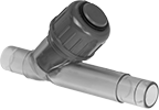
- For Use With: Air, Water
- Piston Material: PVC Plastic
- Seal Material: EPDM Rubber
Visually inspect flow and debris accumulation through the transparent valve body. Insert unthreaded pipe into the socket ends and bond with primer and cement to create a permanent, leak-tight connection. These valves open to allow flow in one direction and close when flow stops or reverses. They have a removable cap that provides easy access to internal components for maintenance.
Flow coefficient (Cv) is the amount of water (in gallons per minute) at 60° F that will flow through a fully open valve with a difference of 1 psi between the inlet and the outlet.
![]() For technical drawings and 3-D models, click on a part number.
For technical drawings and 3-D models, click on a part number.
| Pipe Size | For Pipe Schedule | Flow Coefficient (Cv) | Max. Pressure | Min. Opening Pressure, psi | Temperature Range, °F | Color | End-to-End Lg. | Features | Each | |
PVC Plastic Body | ||||||||||
|---|---|---|---|---|---|---|---|---|---|---|
Socket Connect × Socket Connect | ||||||||||
| 1 | 40, 80 | 21 | 150 psi @ 70° F | 0.29 | 35° to 140° | Clear | 6 7/8" | Removable Cap | 0000000 | 000000 |
Socket-Connect Check Valves for Harsh Chemicals
Insert unthreaded pipe into the socket ends and bond with primer and cement to create a permanent, leak-tight connection. These valves have a plastic body and a fluoroelastomer seal for excellent chemical resistance. They open to allow flow in one direction and close when flow stops or reverses.
Flow coefficient (Cv) is the amount of water (in gallons per minute) at 60° F that will flow through a fully open valve with a difference of 1 psi between the inlet and the outlet.
![]() For technical drawings and 3-D models, click on a part number.
For technical drawings and 3-D models, click on a part number.
- For Use With: Citric Acid, Deionized Water, Diesel Fuel, Ethylene Glycol, Hydrochloric Acid, Isopropyl Alcohol, Kerosene, Mineral Spirits, Nitric Acid, Oil, Phosphoric Acid, Salt Water, Sodium Hypochlorite, Water
- Piston Material: PVC Plastic
- Spring Material: PVC Plastic
- Seal Material: Fluoroelastomer Rubber
| Pipe Size | For Pipe Schedule | Flow Coefficient (Cv) | Max. Pressure | Min. Opening Pressure, psi | Temperature Range, °F | Color | End-to-End Lg. | Each | |
Socket Connect × Socket Connect | |||||||||
|---|---|---|---|---|---|---|---|---|---|
| 1 | 40, 80 | 9 | 150 psi @ 70° F | 2 | 40° to 140° | Dark Gray | 5 3/16" | 000000 | 0000000 |
- For Use With: Citric Acid, Deionized Water, Diesel Fuel, Hydrochloric Acid, Isopropyl Alcohol, Kerosene, Mineral Spirits, Nitric Acid, Oil, Phosphoric Acid, Salt Water, Sodium Hypochlorite, Water
- Piston Material: CPVC Plastic
- Spring Material: CPVC Plastic
- Seal Material: Fluoroelastomer Rubber
| Pipe Size | For Pipe Schedule | Flow Coefficient (Cv) | Max. Pressure | Min. Opening Pressure, psi | Temperature Range, °F | Color | End-to-End Lg. | Each | |
Socket Connect × Socket Connect | |||||||||
|---|---|---|---|---|---|---|---|---|---|
| 1 | 40, 80 | 9 | 150 psi @ 70° F | 2 | 40° to 190° | Light Gray | 5 3/16" | 0000000 | 0000000 |
Clear-View Socket-Connect Check Valves for Harsh Chemicals
- For Use With: Carbon Dioxide, Citric Acid, Deionized Water, Diesel Fuel, Hydrochloric Acid, Methanol, Nitric Acid, Phosphoric Acid, Salt Water, Sulfuric Acid, Water
- Piston Material: PVC Plastic
- Seal Material: Fluoroelastomer Rubber
Visually inspect flow and debris accumulation through the transparent valve body. Insert unthreaded pipe into the socket ends and bond with primer and cement to create a permanent, leak-tight connection. Valves have a PVC body and a fluoroelastomer seal for excellent chemical resistance. They open to allow flow in one direction and close when flow stops or reverses. All have a removable cap that provides easy access to internal components for maintenance.
Flow coefficient (Cv) is the amount of water (in gallons per minute) at 60° F that will flow through a fully open valve with a difference of 1 psi between the inlet and the outlet.
![]() For technical drawings and 3-D models, click on a part number.
For technical drawings and 3-D models, click on a part number.
| Pipe Size | For Pipe Schedule | Flow Coefficient (Cv) | Max. Pressure | Min. Opening Pressure, psi | Temperature Range, °F | Color | End-to-End Lg. | Features | Each | |
PVC Plastic Body | ||||||||||
|---|---|---|---|---|---|---|---|---|---|---|
Socket Connect × Socket Connect | ||||||||||
| 1 | 40, 80 | 21 | 150 psi @ 70° F | 0.29 | 35° to 140° | Clear | 6 7/8" | Removable Cap | 0000000 | 000000 |