McMaster-Carr logo
    Filter by
    System of Measurement
    Number of Poles
    Frequency
    Trip Type
    Manufacturer Series
    Circuit Breaker Interruption Type
    Wire Connection
    Industrial Info Compare
    Reset Type
    U.S.–Mexico–Canada Agreement (USMCA) Qualifying
    Industrial Info Compare
    DFARS Specialty Metals
    Export Control Classification Number (ECCN)
    Industrial Info Snippet
    Enter e-mail addresses in the fields below
    Message
    Cancel
    Comments
    E-mail address (if you would like a response)
    107 Products

    Square D Load-Center Circuit Breakers

    Match these circuit breakers to Square D breaker boxes or panel boards of the same manufacturer series. Because they are thermal-magnetic, these breakers trip two different ways. They either trip when heat is generated by sustained low-level overload current or quickly when the magnetic coil senses a high-current short circuit.
    QO Series
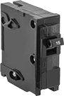
    Image of Product. QO Series, 1 Pole. Front orientation. Circuit Breakers. Square D Load-Center Circuit Breakers, QO Series, 1 Pole—Toggle-Switch Style.
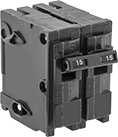
    Image of Product. QO Series, 2 Poles. Front orientation. Circuit Breakers. Square D Load-Center Circuit Breakers, QO Series, 2 Poles—Toggle Switch.
    Image of Product. QO Series, 3 Poles. Front orientation. Circuit Breakers. Square D Load-Center Circuit Breakers, QO Series, 3 Poles—Toggle Switch.

    QO

    Series, 1

    Pole

    QO Series,

    2 Poles

    QO Series, 3

    Poles

    UL 489—They meet UL 489 requirements for branch circuit protection, so they protect downstream equipment and wiring from overloads and short circuits.
    Breakthrough Current @ Voltage—Breakthrough current is the maximum current that the circuit breaker can safely stop in the event of a short circuit.
    Current,
    A
    Voltage
    Freq., Hz
    Breakthrough Current @ Voltage
    Mounting
    Location
    Wire Connection
    Method
    Wd.
    Specs.
    Met
    Certification
    Each
    1 Pole—Toggle-Switch Style
    2048V DC
    120V AC
    240V AC
    50/6010,000 amp @ 120V AC
    10,000 amp @ 240V AC
    5,000 amp @ 48V DC
    Breaker BoxSnap On3/4"UL 489UL Listed
    6782K113000000
     
    2 Poles—Toggle Switch
    2048V DC
    120V AC
    240V AC
    50/6010,000 amp @ 120V AC
    10,000 amp @ 240V AC
    5,000 amp @ 48V DC
    Breaker BoxSnap On1 1/2"UL 489UL Listed
    6782K21300000
     
    3 Poles—Toggle Switch
    2048V DC
    120V AC
    240V AC
    50/6010,000 amp @ 120V AC
    10,000 amp @ 240V AC
    5,000 amp @ 48V DC
    Breaker BoxSnap On2 1/4"UL 489UL Listed
    6782K307000000
     
    QO Series with 6 mA Ground Fault Sensitivity
    Image of Product. QO Series, 1 Pole. Front orientation. Circuit Breakers. Square D Load-Center Circuit Breakers, QO Series, 1 Pole—Toggle-Switch Style.
    Image of Product. QO Series, 2 Poles. Front orientation. Circuit Breakers. Square D Load-Center Circuit Breakers, QO Series, 2 Poles—Toggle Switch.

    QO

    Series, 1

    Pole

    QO Series,

    2 Poles

    Circuit breakers with ground fault sensitivity will trip if they detect a current leak above 6 mA. This minimizes the risk of electric shock to workers and equipment.
    UL 489—They meet UL 489 requirements for branch circuit protection, so they protect downstream equipment and wiring from overloads and short circuits.
    Breakthrough Current @ Voltage—Breakthrough current is the maximum current that the circuit breaker can safely stop in the event of a short circuit.
    Current,
    A
    Voltage, V AC
    Freq., Hz
    Breakthrough Current @ Voltage
    Mounting
    Location
    Wire Connection
    Method
    Wd.
    Specs.
    Met
    Certification
    Each
    1 Pole—Toggle-Switch Style
    2012050/6010,000 amp @ 120V ACBreaker BoxSnap On3/4"UL 489UL Listed
    6782K3020000000
     
    2 Poles—Toggle Switch
    20120
    240
    50/6010,000 amp @ 120V AC
    10,000 amp @ 240V AC
    Breaker BoxSnap On1.5"UL 489UL Listed
    6782K304000000
     
    QOB Series
    Image of Product. QOB Series, 1 Pole. Front orientation. Circuit Breakers. Square D Load-Center Circuit Breakers, QOB Series, 1 Pole—Toggle-Switch Style.
    Image of Product. QOB Series, 2 Poles. Front orientation. Circuit Breakers. Square D Load-Center Circuit Breakers, QOB Series, 2 Poles—Toggle Switch.
    Image of Product. QOB Series, 3 Poles. Front orientation. Circuit Breakers. Square D Load-Center Circuit Breakers, QOB Series, 3 Poles—Toggle Switch.

    QOB

    Series,

    1 Pole

    QOB

    Series, 2

    Poles

    QOB Series,

    3 Poles

    UL 489—They meet UL 489 requirements for branch circuit protection, so they protect downstream equipment and wiring from overloads and short circuits.
    Breakthrough Current @ Voltage—Breakthrough current is the maximum current that the circuit breaker can safely stop in the event of a short circuit.
    Current,
    A
    Voltage
    Freq., Hz
    Breakthrough Current @ Voltage
    Mounting
    Location
    Wire Connection
    Wd.
    Specs.
    Met
    Certification
    Each
    1 Pole—Toggle-Switch Style
    2048V DC
    120V AC
    240V AC
    50/6010,000 amp @ 120V AC
    10,000 amp @ 240V AC
    5,000 amp @ 48V DC
    Panel BoardScrew-Clamp Terminal
    3/4"UL 489UL Listed
    6782K512000000
     
    2 Poles—Toggle Switch
    2048V DC
    120V AC
    240V AC
    50/6010,000 amp @ 120V AC
    10,000 amp @ 240V AC
    5,000 amp @ 48V DC
    Panel BoardScrew-Clamp Terminal
    1 1/2"UL 489UL Listed
    6782K61200000
     
    3 Poles—Toggle Switch
    2048V DC
    120V AC
    240V AC
    50/6010,000 amp @ 120V AC
    10,000 amp @ 240V AC
    5,000 amp @ 48V DC
    Panel BoardScrew-Clamp Terminal
    2 1/4"UL 489UL Listed
    6782K712000000
     
    Homeline Series
    Image of Product. Homeline Series, 1 Pole. Front orientation. Circuit Breakers. Square D Load-Center Circuit Breakers, Homeline Series, 1 Pole—Toggle-Switch Style.
    Image of Product. Homeline Series, 2 Poles. Front orientation. Circuit Breakers. Square D Load-Center Circuit Breakers, Homeline Series, 1 Pole with Tandem Circuit—Toggle Switch.
    Image of Product. Homeline Series, 3 Poles. Front orientation. Circuit Breakers. Square D Load-Center Circuit Breakers, Homeline Series, 2 Poles—Toggle Switch.

    Homeline

    Series, 1

    Pole

    Homeline

    Series, 2

    Poles

    Homeline

    Series, 3

    Poles

    UL 489—They meet UL 489 requirements for branch circuit protection, so they protect downstream equipment and wiring from overloads and short circuits.
    Breakthrough Current @ Voltage—Breakthrough current is the maximum current that the circuit breaker can safely stop in the event of a short circuit.
    Current,
    A
    Voltage, V AC
    Freq., Hz
    Breakthrough Current @ Voltage
    Mounting
    Location
    Wire Connection
    Method
    Wd.
    Specs.
    Met
    Certification
    Each
    1 Pole—Toggle-Switch Style
    20120
    240
    50/6010,000 amp @ 120V AC
    10,000 amp @ 240V AC
    Breaker BoxSnap On1"UL 489UL Listed
    69225K72000000
     
    1 Pole with Tandem Circuit—Toggle Switch
    20120
    240
    50/6010,000 amp @ 120V AC
    10,000 amp @ 240V AC
    Breaker BoxSnap On1"UL 489UL Listed
    69225K8400000
     
    2 Poles—Toggle Switch
    20120
    240
    50/6010,000 amp @ 120V AC
    10,000 amp @ 240V AC
    Breaker BoxSnap On2"UL 489UL Listed
    69225K7500000
     
    Homeline Series with 6 mA Ground Fault Sensitivity
    Image of Product. Homeline Series, 1 Pole. Front orientation. Circuit Breakers. Square D Load-Center Circuit Breakers, Homeline Series, 1 Pole—Toggle-Switch Style.
    Image of Product. Homeline Series, 3 Poles. Front orientation. Circuit Breakers. Square D Load-Center Circuit Breakers, Homeline Series, 2 Poles—Toggle Switch.

    Homeline

    Series, 1

    Pole

    Homeline

    Series, 3

    Poles

    Circuit breakers with ground fault sensitivity will trip if they detect a current leak above 6 mA. This minimizes the risk of electric shock to workers and equipment.
    UL 489—They meet UL 489 requirements for branch circuit protection, so they protect downstream equipment and wiring from overloads and short circuits.
    Breakthrough Current @ Voltage—Breakthrough current is the maximum current that the circuit breaker can safely stop in the event of a short circuit.
    Current,
    A
    Voltage, V AC
    Freq., Hz
    Breakthrough Current @ Voltage
    Mounting
    Location
    Wire Connection
    Method
    Wd.
    Specs.
    Met
    Certification
    Each
    1 Pole—Toggle-Switch Style
    2012050/6010,000 amp @ 120V ACBreaker BoxSnap On1"UL 489UL Listed
    69225K820000000
     
    2 Poles—Toggle Switch
    20120
    240
    50/6010,000 amp @ 120V AC
    10,000 amp @ 240V AC
    Breaker BoxSnap On2"UL 489UL Listed
    69225K104000000
     

    DIN-Rail Mount Branch Circuit Breakers
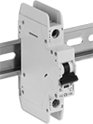
    Image of ProductInUse. Front orientation. Circuit Breakers. DIN-Rail Mount Branch Circuit Breakers.
    Image of Product. Extension Terminal. Front orientation. Circuit Breakers. DIN-Rail Mount Branch Circuit Breakers.
    Image of Product. Distribution Bar Terminal Cover. Front orientation. Circuit Breakers. DIN-Rail Mount Branch Circuit Breakers.
    Image of Product. Shunt Trip. Front orientation. Circuit Breakers. DIN-Rail Mount Branch Circuit Breakers.

    Extension

    Terminal

    Distribution

    Bar Terminal

    Cover

    Shunt

    Trip

    Image of Product. Auxiliary Contact. Front orientation. Circuit Breakers. DIN-Rail Mount Branch Circuit Breakers.
    Image of Product. Distribution Bar. Front orientation. Circuit Breakers. DIN-Rail Mount Branch Circuit Breakers.

    Auxiliary

    Contact

    Distribution Bar

    Mount these circuit breakers directly to DIN rail to protect equipment and wiring in an area of your facility from overloads and short circuits. Because they are thermal-magnetic, these breakers trip two ways. They either trip when heat is generated slowly by consistent low-level overload current, or they trip quickly when the magnetic coil senses a high-current short circuit.
    Distribution bars simplify wiring by powering multiple adjacent circuit breakers without needing separate wires for each one. This cuts down on assembly time and space.
    Distribution bar terminal covers shield unused, live terminals on distribution bars to prevent injury and damage.
    Auxiliary contacts send a signal to other equipment when the circuit trips. They can activate a warning light, initiate a shutdown, or start a backup power source.
    Shunt trips receive a signal from equipment to trip your circuit breaker in situations other than overload or short circuit conditions. For example, use them with a smoke detector to shut off power to a system in the event of a fire.
    Extension terminals raise the wire connection point above distribution bars for easy access to connect power to a set of circuit breakers.
    B Trip
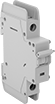
    Image of Product. Front orientation. Circuit Breakers. DIN-Rail Mount Branch Circuit Breakers, 1 Pole—Toggle-Switch Style.
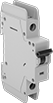
    Image of Product. Front orientation. Circuit Breakers. DIN-Rail Mount Branch Circuit Breakers, 2 Poles—Toggle-Switch Style.
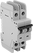
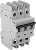
    Image of Product. Front orientation. Circuit Breakers. DIN-Rail Mount Branch Circuit Breakers, 3 Poles—Toggle-Switch Style.

    1

    Pole—Toggle-Switch

    Style

    2

    Poles—Toggle-Switch

    Style

    3

    Poles—Toggle-Switch

    Style

    B-trip circuit breakers are best for protecting sensitive equipment, such as programmable logic controllers (PLCs) and sensors, which could be damaged by a spike in current. These circuit breakers will trip if a rush of current reaches 3 to 5 times their rated current.
    UL 489—They meet UL 489 requirements for branch circuit protection and are certified as current limiting, so they protect equipment by minimizing passing current during a short circuit.
    Voltage
    Freq., Hz
    For DIN
    Rail Size, mm
    Wire Connection
    Ht.
    Wd.
    Dp.
    Temp. Range,
    ° F
    Specs. Met
    Certification
    Current,
    A
    Each
    1 Pole—Toggle-Switch Style
    48V DC
    277V AC
    50/6035Screw-Clamp Terminal
    4.13"0.7"2.36"-10 to 165UL 489, IEC 60947-2CSA Certified, CE Marked
    205789T201000000
     
    2 Poles—Toggle-Switch Style
    96V DC
    277V AC
    480YV AC/277V AC
    50/6035Screw-Clamp Terminal
    4.13"1.4"2.36"-10 to 165UL 489, IEC 60947-2CSA Certified, CE Marked
    205789T20200000
     
    3 Poles—Toggle-Switch Style
    277V AC
    480YV AC/277V AC
    50/6035Screw-Clamp Terminal
    4.13"2.09"2.36"-10 to 165UL 489, IEC 60947-2CSA Certified, CE Marked
    205789T203000000
     
    Accessories for Breakers
    C Trip
    Image of Product. Front orientation. Circuit Breakers. DIN-Rail Mount Branch Circuit Breakers, 1 Pole—Toggle-Switch Style.
    Image of Product. Front orientation. Circuit Breakers. DIN-Rail Mount Branch Circuit Breakers, 2 Poles—Toggle-Switch Style.
    Image of Product. Front orientation. Circuit Breakers. DIN-Rail Mount Branch Circuit Breakers, 3 Poles—Toggle-Switch Style.

    1

    Pole—Toggle-Switch

    Style

    2

    Poles—Toggle-Switch

    Style

    3

    Poles—Toggle-Switch

    Style

    C-trip circuit breakers are the most common. They’re best for applications such as lighting and control panels, where equipment startup causes a moderate spike in current. They won’t trip until a rush of current reaches 5 to 10 times their rated current.
    UL 489—They meet UL 489 requirements for branch circuit protection and are certified as current limiting, so they protect equipment by minimizing passing current during a short circuit.
    Breakthrough Current @ Voltage—Breakthrough current is the maximum current that the circuit breaker can safely stop in the event of a short circuit.
    Voltage
    Freq., Hz
    Breakthrough Current @ Voltage
    For DIN
    Rail Size, mm
    Mounting
    Location
    Wire Connection
    Ht.
    Wd.
    Dp.
    Temp. Range,
    ° F
    Specs. Met
    Certification
    Current,
    A
    Each
    1 Pole—Toggle-Switch Style
     
    Thermal/Magnetic
    48V DC
    277V AC
    50/6014,000 amp @ 277V AC
    14,000 amp @ 48V DC
    35DIN RailScrew-Clamp Terminal
    4.13"0.7"2.36"-10 to 165UL 489, IEC 60947-2CSA Certified, CE Marked
    205789T74000000
     
    2 Poles—Toggle-Switch Style
     
    Thermal/Magnetic
    96V DC
    277V AC
    480YV AC/277V AC
    50/6014,000 amp @ 277V AC
    14,000 amp @ 480V AC
    14,000 amp @ 96V DC
    35DIN RailScrew-Clamp Terminal
    4.13"1.4"2.36"-10 to 165UL 489, IEC 60947-2CSA Certified, CE Marked
    205789T8400000
    250V DC
    125V DC
    50/6010,000 amp @ 125V DC
    10,000 amp @ 250V DC
    35DIN RailScrew-Clamp Terminal
    4.13"1.4"2.36"-10 to 165UL 489, IEC 60947-2CSA Certified, CE Marked
    205789T20500000
     
    3 Poles—Toggle-Switch Style
     
    Thermal/Magnetic
    277V AC
    480YV AC/277V AC
    50/6014,000 amp @ 277V AC
    14,000 amp @ 480V AC
    35DIN RailScrew-Clamp Terminal
    4.13"2.09"2.36"-10 to 165UL 489, IEC 60947-2CSA Certified, CE Marked
    205789T94000000
     
    Accessories for Breakers
    D Trip
    Image of Product. Front orientation. Circuit Breakers. DIN-Rail Mount Branch Circuit Breakers, 1 Pole—Toggle-Switch Style.
    Image of Product. Front orientation. Circuit Breakers. DIN-Rail Mount Branch Circuit Breakers, 2 Poles—Toggle-Switch Style.
    Image of Product. Front orientation. Circuit Breakers. DIN-Rail Mount Branch Circuit Breakers, 3 Poles—Toggle-Switch Style.

    1

    Pole—Toggle-Switch

    Style

    2

    Poles—Toggle-Switch

    Style

    3

    Poles—Toggle-Switch

    Style

    D-trip circuit breakers prevent nuisance tripping, so they are best for equipment that has a high spike in current at startup, such as transformers, power supplies, and heaters. They will not trip unless a rush of current reaches 10 to 20 times their rated current.
    UL 489—They meet UL 489 requirements for branch circuit protection and are certified as current limiting, so they protect equipment by minimizing passing current during a short circuit.
    Breakthrough Current @ Voltage—Breakthrough current is the maximum current that the circuit breaker can safely stop in the event of a short circuit.
    Current,
    A
    Voltage
    Freq., Hz
    Breakthrough Current @ Voltage
    For DIN
    Rail Size, mm
    Mounting
    Location
    Wire Connection
    Ht.
    Wd.
    Dp.
    Temp. Range,
    ° F
    Specs. Met
    Certification
    Each
    1 Pole—Toggle-Switch Style
     
    Thermal/Magnetic
    2048V DC
    277V AC
    50/6014,000 amp @ 277V AC
    14,000 amp @ 48V DC
    35DIN RailScrew-Clamp Terminal
    4.13"0.7"2.36"-10 to 165UL 489, IEC 60947-2CSA Certified, CE Marked
    5789T416000000
     
    2 Poles—Toggle-Switch Style
     
    Thermal/Magnetic
    2096V DC
    277V AC
    480YV AC/277V AC
    50/6014,000 amp @ 277V AC
    14,000 amp @ 480V AC
    14,000 amp @ 96V DC
    35DIN RailScrew-Clamp Terminal
    4.13"1.4"2.36"-10 to 165UL 489, IEC 60947-2CSA Certified, CE Marked
    5789T51600000
     
    3 Poles—Toggle-Switch Style
     
    Thermal/Magnetic
    20277V AC
    480YV AC/277V AC
    50/6014,000 amp @ 277V AC
    14,000 amp @ 480V AC
    35DIN RailScrew-Clamp Terminal
    4.13"2.09"2.36"-10 to 165UL 489, IEC 60947-2CSA Certified, CE Marked
    5789T616000000
     
    Accessories for Breakers

    DIN-Rail Mount Equipment Circuit Breakers
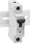
    Image of ProductInUse. Front orientation. Circuit Breakers. DIN-Rail Mount Equipment Circuit Breakers.
    Image of Product. Auxiliary Contact. Front orientation. Circuit Breakers. DIN-Rail Mount Equipment Circuit Breakers.
    Image of Product. Distribution Bar. Front orientation. Circuit Breakers. DIN-Rail Mount Equipment Circuit Breakers.
    Image of Product. Distribution Bar Terminal Cover. Front orientation. Circuit Breakers. DIN-Rail Mount Equipment Circuit Breakers.

    Auxiliary

    Contact

    Distribution Bar

    Distribution Bar

    Terminal Cover

    Image of Product. Distribution Bar End Cover. Front orientation. Circuit Breakers. DIN-Rail Mount Equipment Circuit Breakers.
    Image of Product. Shunt Trip. Front orientation. Circuit Breakers. DIN-Rail Mount Equipment Circuit Breakers.
    Image of Product. Extension Terminal. Front orientation. Circuit Breakers. DIN-Rail Mount Equipment Circuit Breakers.

    Distribution

    Bar End Cover

    Shunt

    Trip

    Extension

    Terminal

    Also known as supplemental protectors, these circuit breakers mount directly to DIN rail downstream from a branch circuit breaker to protect a single piece of equipment. Because they are thermal-magnetic, these breakers trip two ways. They either trip when heat is generated slowly by consistent low-level overload current, or they trip quickly when the magnetic coil senses a high-current short circuit.
    Distribution bars simplify wiring by powering multiple adjacent circuit breakers without needing separate wires for each one. This cuts down on assembly time and space. Cut them to the number of terminals that you need.
    Distribution bar terminal covers shield unused, live terminals on distribution bars to prevent injury and damage.
    Auxiliary contacts send a signal to other equipment when the circuit trips. They can activate a warning light, initiate a shutdown, or start a backup power source.
    Shunt trips receive a signal from equipment to trip your circuit breaker in situations other than overload or short circuit conditions. For example, use them with a smoke detector to shut off power to a system in the event of a fire.
    Extension terminals raise the wire connection point above distribution bars for easy access to connect power to a set of circuit breakers.
    Distribution bar end covers seal the live ends of distribution bars to prevent injury and damage.
    B Trip
    Image of Product. Front orientation. Circuit Breakers. DIN-Rail Mount Equipment Circuit Breakers, 1 Pole—Toggle-Switch Style.
    Image of Product. Front orientation. Circuit Breakers. DIN-Rail Mount Equipment Circuit Breakers, 2 Poles—Toggle-Switch Style.
    Image of Product. Front orientation. Circuit Breakers. DIN-Rail Mount Equipment Circuit Breakers, 3 Poles—Toggle-Switch Style.

    1

    Pole—Toggle-Switch

    Style

    2

    Poles—Toggle-Switch

    Style

    3

    Poles—Toggle-Switch

    Style

    B-trip circuit breakers are best for protecting sensitive equipment, such as programmable logic controllers (PLCs) and sensors, which could be damaged by a spike in current. These circuit breakers will trip if a rush of current reaches 3 to 5 times their rated current.
    UL 1077—They are rated UL 1077 for protection against overloads and short circuits.
    Current,
    A
    Voltage
    Freq., Hz
    Breakthrough Current @ Voltage
    For DIN
    Rail Size, mm
    Mounting
    Location
    Wire Connection
    Ht.
    Wd.
    Dp.
    Temp. Range,
    ° F
    Specs. Met
    Certification
    Each
    1 Pole—Toggle-Switch Style
     
    Thermal/Magnetic
    2048V DC
    277V AC
    50/6010,000 amp @ 277V AC
    10,000 amp @ 48V DC
    35DIN RailScrew-Clamp Terminal
    3.15"0.7"2.36"-40 to 165UL 1077, IEC 60947-2UL Listed, CSA Certified, CE Marked
    7026K614000000
     
    2 Poles—Toggle-Switch Style
     
    Thermal/Magnetic
    2096V DC
    277V AC
    480YV AC/277V AC
    50/6010,000 amp @ 277V AC
    10,000 amp @ 480V AC
    10,000 amp @ 96V DC
    35DIN RailScrew-Clamp Terminal
    3.15"1.4"2.36"-40 to 165UL 1077, IEC 60947-2UL Listed, CSA Certified, CE Marked
    7026K681000000
     
    3 Poles—Toggle-Switch Style
     
    Thermal/Magnetic
    20277V AC
    480YV AC/277V AC
    50/6010,000 amp @ 277V AC
    10,000 amp @ 480V AC
    35DIN RailScrew-Clamp Terminal
    3.15"2.09"2.36"-40 to 165UL 1077, IEC 60947-2UL Listed, CSA Certified, CE Marked
    7026K626000000
     
    Accessories for Breakers
    C Trip
    Image of Product. Front orientation. Circuit Breakers. DIN-Rail Mount Equipment Circuit Breakers, 1 Pole—Toggle-Switch Style.
    Image of Product. Front orientation. Circuit Breakers. DIN-Rail Mount Equipment Circuit Breakers, 2 Poles—Toggle-Switch Style.
    Image of Product. Front orientation. Circuit Breakers. DIN-Rail Mount Equipment Circuit Breakers, 3 Poles—Toggle-Switch Style.

    1

    Pole—Toggle-Switch

    Style

    2

    Poles—Toggle-Switch

    Style

    3

    Poles—Toggle-Switch

    Style

    C-trip circuit breakers are the most common. They’re best for applications such as lighting and control panels, where equipment startup causes a moderate spike in current. They won’t trip until a rush of current reaches 5 to 10 times their rated current.
    UL 1077—They are rated UL 1077 for protection against overloads and short circuits.
    Current,
    A
    Voltage
    Freq., Hz
    Breakthrough Current @ Voltage
    For DIN
    Rail Size, mm
    Mounting
    Location
    Wire Connection
    Ht.
    Wd.
    Dp.
    Temp. Range,
    ° F
    Specs. Met
    Certification
    Each
    1 Pole—Toggle-Switch Style
     
    Thermal/Magnetic
    2048V DC
    277V AC
    50/6010,000 amp @ 277V AC
    10,000 amp @ 48V DC
    35DIN RailScrew-Clamp Terminal
    3.15"0.7"2.36"-40 to 165UL 1077, IEC 60947-2UL Listed, CSA Certified, CE Marked
    7026K64000000
     
    2 Poles—Toggle-Switch Style
     
    Thermal/Magnetic
    2096V DC
    277V AC
    480YV AC/277V AC
    50/6010,000 amp @ 277V AC
    10,000 amp @ 480V AC
    10,000 amp @ 96V DC
    35DIN RailScrew-Clamp Terminal
    3.15"1.4"2.36"-40 to 165UL 1077, IEC 60947-2UL Listed, CSA Certified, CE Marked
    7026K74000000
     
    3 Poles—Toggle-Switch Style
     
    Thermal/Magnetic
    20277V AC
    480YV AC/277V AC
    50/6010,000 amp @ 277V AC
    10,000 amp @ 480V AC
    35DIN RailScrew-Clamp Terminal
    3.15"2.09"2.36"-40 to 165UL 1077, IEC 60947-2UL Listed, CSA Certified, CE Marked
    7026K84000000
     
    Accessories for Breakers
    D Trip
    Image of Product. Front orientation. Circuit Breakers. DIN-Rail Mount Equipment Circuit Breakers, 1 Pole—Toggle-Switch Style.
    Image of Product. Front orientation. Circuit Breakers. DIN-Rail Mount Equipment Circuit Breakers, 2 Poles—Toggle-Switch Style.
    Image of Product. Front orientation. Circuit Breakers. DIN-Rail Mount Equipment Circuit Breakers, 3 Poles—Toggle-Switch Style.

    1

    Pole—Toggle-Switch

    Style

    2

    Poles—Toggle-Switch

    Style

    3

    Poles—Toggle-Switch

    Style

    D-trip circuit breakers prevent nuisance tripping, so they are best for equipment that has a high spike in current at startup, such as transformers, power supplies, and heaters. They will not trip unless a rush of current reaches 10 to 20 times their rated current.
    UL 1077—They are rated UL 1077 for protection against overloads and short circuits.
    Current,
    A
    Voltage
    Freq., Hz
    Breakthrough Current @ Voltage
    For DIN
    Rail Size, mm
    Mounting
    Location
    Wire Connection
    Ht.
    Wd.
    Dp.
    Temp. Range,
    ° F
    Specs. Met
    Certification
    Each
    1 Pole—Toggle-Switch Style
     
    Thermal/Magnetic
    2048V DC
    277V AC
    50/605,000 amp @ 277V AC
    5,000 amp @ 48V DC
    35DIN RailScrew-Clamp Terminal
    3.15"0.7"2.36"-40 to 165UL 1077, IEC 60947-2UL Listed, CSA Certified, CE Marked
    7026K316000000
     
    2 Poles—Toggle-Switch Style
     
    Thermal/Magnetic
    2096V DC
    277V AC
    480YV AC/277V AC
    50/605,000 amp @ 277V AC
    5,000 amp @ 480V AC
    5,000 amp @ 96V DC
    35DIN RailScrew-Clamp Terminal
    3.15"1.4"2.36"-40 to 165UL 1077, IEC 60947-2UL Listed, CSA Certified, CE Marked
    7026K416000000
     
    3 Poles—Toggle-Switch Style
     
    Thermal/Magnetic
    20277V AC
    480YV AC/277V AC
    50/605,000 amp @ 277V AC
    5,000 amp @ 480V AC
    35DIN RailScrew-Clamp Terminal
    3.15"2.09"2.36"-40 to 165UL 1077, IEC 60947-2UL Listed, CSA Certified, CE Marked
    7026K516000000
     
    Accessories for Breakers

    Siemens Load-Center Circuit Breakers

    Image of Product. Front orientation. Circuit Breakers. Siemens Load-Center Circuit Breakers, 1 Pole—Toggle-Switch Style.
    Image of Product. Front orientation. Circuit Breakers. Siemens Load-Center Circuit Breakers, 2 Poles—Toggle-Switch Style.

    1

    Pole—Toggle-Switch

    Style

    2

    Poles—Toggle-Switch

    Style

    Use with Siemens EQ series breaker boxes. Because they are thermal-magnetic, these circuit breakers trip two different ways. They either trip when heat is generated slowly by consistent low-level overload current or quickly when the magnetic coil senses a high-current short circuit.
    UL 489—These circuit breakers meet UL 489 requirements for branch circuit protection, so they protect downstream equipment and wiring from overloads and short circuits.
    Breakthrough Current @ Voltage—Breakthrough current is the maximum current that the circuit breaker can safely stop in the event of a short circuit.
    Current,
    A
    Voltage, V AC
    Freq.,
    Hz
    Breakthrough Current @ Voltage
    Mounting
    Location
    Wire Connection
    Wd.
    Specs.
    Met
    Each
    1 Pole—Toggle-Switch Style
     
    Thermal/Magnetic
    20120
    240
    6010,000 amp @ 120V AC
    10,000 amp @ 240V AC
    Breaker BoxScrew-Clamp Terminal
    1"UL 4895259T42000000
     
    2 Poles—Toggle-Switch Style
     
    Thermal/Magnetic
    20120
    240
    6010,000 amp @ 120V AC
    10,000 amp @ 240V AC
    Breaker BoxScrew-Clamp Terminal
    2"UL 4895259T5200000
     

    Cutler-Hammer Load-Center Circuit Breakers
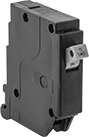
    Image of Product. Front orientation. Circuit Breakers. Cutler-Hammer Load-Center Circuit Breakers, 1 Pole—Toggle-Switch Style.
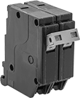
    Image of Product. Front orientation. Circuit Breakers. Cutler-Hammer Load-Center Circuit Breakers, 2 Poles—Toggle-Switch Style.

    1

    Pole—Toggle-Switch

    Style

    2

    Poles—Toggle-Switch

    Style

    Install these circuit breakers into Cutler-Hammer CH series breaker boxes. Because these circuit breakers are thermal-magnetic, they trip two different ways. They either trip when heat is generated slowly by consistent low-level overload current or quickly when the magnetic coil senses a high-current short circuit.
    UL 489—They meet UL 489 requirements for branch circuit protection and are certified as current limiting, so they protect equipment by minimizing passing current during a short circuit.
    Breakthrough Current @ Voltage—Breakthrough current is the maximum current that the circuit breaker can safely stop in the event of a short circuit.
    Current,
    A
    Voltage, V AC
    Freq.,
    Hz
    Breakthrough Current @ Voltage
    Mounting
    Location
    Wire Connection
    Wd.
    Specs.
    Met
    Each
    1 Pole—Toggle-Switch Style
     
    Thermal/Magnetic
    20120
    240
    6010,000 amp @ 120V AC
    10,000 amp @ 240V AC
    Breaker BoxScrew-Clamp Terminal
    3/4"UL 4895259T72000000
     
    2 Poles—Toggle-Switch Style
     
    Thermal/Magnetic
    20120
    240
    6010,000 amp @ 120V AC
    10,000 amp @ 240V AC
    Breaker BoxScrew-Clamp Terminal
    1 1/2"UL 4895259T8200000
     

    Surface-Mount GFCIs

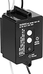
    Image of Product. Front orientation. Circuit Interrupters. Surface-Mount GFCIs.
    Mount and hardwire these GFCIs to your equipment to provide ground fault protection. They will trip if a ground fault is detected; press the button to reset. In case of a power outage, the reset is automatic.
    Electrical
    Connection
    Voltage,
    V AC
    Current,
    amp
    Input
    Output
    Ht.
    Wd.
    Dp.
    Features
    No. of Mounting
    Holes
    Mounting
    Hole Dia.
    Mounting Fasteners
    Included
    Certification
    Each
    12020Wire Leads
    Wire Leads
    3.8"2.3"2.2"Reset Button, Test Button, Power-Indicating Light23/16"NoUL Recognized Component
    72155K73000000

    High-Temperature Panel-Mount Circuit Breakers
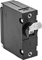
    Image of Product. Front orientation. Circuit Breakers. High-Temperature Panel-Mount Circuit Breakers , 1 Pole—Toggle-Switch Style.
    Image of Product. Front orientation. Circuit Breakers. High-Temperature Panel-Mount Circuit Breakers , 2 Poles—Toggle-Switch Style.

    1

    Pole—Toggle-Switch

    Style

    2

    Poles—Toggle-Switch

    Style

    Unlike breakers that trip thermally, these breakers have a hydraulic-magnetic trip mechanism, so they aren’t affected by changes in temperature. Instead, these circuit breakers trip when they hydraulically sense consistent low-level overload current, or they trip quickly when the magnetic coil senses a high-current short circuit. Use the threaded holes on the face to install them through panels, enclosure covers, or walls to keep them close to the equipment they protect.
    Breakthrough Current @ Voltage—Breakthrough current is the maximum current that the circuit breaker can safely stop in the event of a short circuit.
    For Panel
    Cutout
    Mounting
    Holes
    Current,
    A
    Voltage
    Freq., Hz
    Breakthrough Current @ Voltage
    Temp. Range,
    ° F
    Ht.
    Wd.
    Dia.
    Dp. Behind
    Panel
    No.
    of
    Thread
    Size
    Mounting Fasteners
    Included
    Wire Connection
    Ht.
    Wd.
    Each
    1 Pole—Toggle-Switch Style
    2080V DC
    277V AC
    50/605,000 amp @ 277V AC
    7,500 amp @ 80V DC
    -40 to 1850.63"2"26-32
    NoQuick-Disconnect Terminal
    2"0.75"72015K114000000
     
    2 Poles—Toggle-Switch Style
    20250V AC50/601,500 amp @ 250V AC-40 to 1851.45"1.52"2.573"46-32
    NoScrew Terminal
    2.5"1.5"72015K42000000
     

    Space-Saving Panel-Mount Branch Circuit Breakers
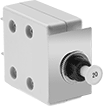
    Image of Product. Front orientation. Circuit Breakers. Space-Saving Panel-Mount Branch Circuit Breakers.
    Small enough to fit in tight spaces, these circuit breakers mount through panels. They are thermal, so they use the heat generated in overcurrent situations to trip the breaker.
    UL 489—These circuit breakers are UL 489-rated for branch circuit protection.
    Breakthrough Current @ Voltage—Breakthrough current is the maximum current that the circuit breaker can safely stop in the event of a short circuit.
    Screw On
    Current,
    A
    Voltage,
    V AC
    Freq., Hz
    Breakthrough Current
    @ Voltage
    For Panel
    Cutout Dia.
    Dp. Behind
    Panel
    Mounting
    Location
    Mounting Fasteners
    Included
    Wire Connection
    Quick-Disconnect
    Tab Wd.
    Temp. Range,
    ° F
    Specs.
    Met
    Certification
    Each
    1 Pole—Push-Button Style
     
    Thermal
    2012050/605,000 amp @ 120V AC0.38"1.43"PanelYesQuick-Disconnect Terminal
    0.25"35 to 140UL 489UL Listed, CSA Certified
    3851K12000000
     

    Panel-Mount Equipment Circuit Breakers
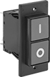
    Mount these breakers, also known as supplemental protectors, through panels downstream from a branch circuit breaker to protect a single piece of equipment. These breakers can also be used as on/off switches. All are thermal, so they use the heat generated in overcurrent situations to trip the breaker.
    Push-Button Style—Screw-On Mount
    Image of Product. Front orientation. Circuit Breakers. Panel-Mount Equipment Circuit Breakers, Push Button Manual Reset.
    UL 1077—They are rated UL 1077 for protection against overloads and short circuits.
    Breakthrough Current @ Voltage—Breakthrough current is the maximum current that the circuit breaker can safely stop in the event of a short circuit.
    For Panel
    Cutout
    Mounting
    Holes
    Current,
    A
    Voltage
    Freq., Hz
    Breakthrough Current @ Voltage
    Ht.
    Wd.
    Dp. Behind
    Panel
    No.
    of
    Dia.
    Mounting Fasteners
    Included
    Quick-Disconnect
    Tab Wd.
    Temp. Range,
    ° F
    Specs.
    Met
    Certification
    Each
    1 Pole
    2060V DC
    240V AC
    50/601,000 amp @ 240V AC
    1,000 amp @ 60V DC
    1.98"0.99"1.96"20.15"No0.25"15 to 130UL 1077UL Recognized Component, CSA Certified
    3931T44000000
     
    2 Poles
    2060V DC
    240V AC
    50/601,000 amp @ 240V AC
    1,000 amp @ 60V DC
    1.98"0.99"1.96"20.15"No0.25"15 to 130UL 1077UL Recognized Component, CSA Certified
    3931T5400000
     
    Circuit Breaker Covers
    Rocker-Switch Style—Snap-In Mount
    Image of Product. Front orientation. Circuit Breakers. Panel-Mount Equipment Circuit Breakers, Rocker Switch Manual Reset.
    UL 1077—They are rated UL 1077 for protection against overloads and short circuits.
    Breakthrough Current @ Voltage—Breakthrough current is the maximum current that the circuit breaker can safely stop in the event of a short circuit.
    For Panel
    Cutout
    Current,
    A
    Voltage
    Freq., Hz
    Breakthrough Current @ Voltage
    Ht.
    Wd.
    Dp. Behind
    Panel
    Quick-Disconnect
    Tab Wd.
    Temp. Range,
    ° F
    Specs.
    Met
    Certification
    Each
    1 Pole
    2060V DC
    240V AC
    50/601,000 amp @ 240V AC
    1,000 amp @ 60V DC
    1.77"0.85"1 3/4"0.25"15 to 130UL 1077UL Recognized Component, CSA Certified
    3931T14000000
     
    2 Poles
    2060V DC
    240V AC
    50/601,000 amp @ 240V AC
    1,000 amp @ 60V DC
    1.77"0.85"1 3/4"0.25"15 to 130UL 1077UL Recognized Component, CSA Certified
    3931T2400000
     
    Circuit Breaker Covers

    Blade-Style Circuit Breakers

    Protect against overload and short circuits in low-voltage automotive and other electronic applications. These circuit breakers can replace type ATC, AF, ATO, and 257 blade-style fuses. They are thermal, so they trip when heat is generated by overload current.
    Automatic Reset
    Image of Product. Front orientation. Circuit Breakers. Blade-Style Circuit Breakers, Automatic Reset.
    Automatic reset breakers don’t require you to manually reset them after they trip, so they’re good for areas where the breaker isn’t easily accessed. These breakers reset once they cool. However, they will trip repeatedly if the overcurrent condition continues.
    Breakthrough Current @ Voltage—Breakthrough current is the maximum current that the circuit breaker can safely stop in the event of a short circuit.
    Current,
    A
    Breakthrough Current
    @ Voltage
    Mounting
    Location
    Ht.
    Wd.
    Blade
    Ht.
    Temp. Range,
    ° F
    Enclosure
    Rating
    Specs.
    Met
    Each
    12V DC
    202,000 amp @ 12V DCFuse Block0.95"0.79"0.25"-40 to 185IP54
    SAE J5534212T1500000
     
    Manual Reset—Push-Button Style
    Image of Product. Front orientation. Circuit Breakers. Blade-Style Circuit Breakers, Manual Reset—Push-Button Style.
    Manual reset breakers require you to push a button after they trip.
    Breakthrough Current @ Voltage—Breakthrough current is the maximum current that the circuit breaker can safely stop in the event of a short circuit.
    Current,
    A
    Breakthrough Current
    @ Voltage
    Mounting
    Location
    Ht.
    Wd.
    Blade
    Ht.
    Temp. Range,
    ° F
    Enclosure
    Rating
    Specs.
    Met
    Each
    24V DC
    202,000 amp @ 24V DCFuse Block1.16"0.79"0.25"-40 to 185IP30
    4212T35000000
     
    48V DC
    202,000 amp @ 48V DCFuse Block1 1/2"0.87"0.25"-40 to 185IP40
    SAE J5534212T4900000
     

    Extension Cord GFCI Converters

    Image of Product. Front orientation. Extension Cord Circuit Interrupter Converters. Extension Cord GFCI Converters, Inline GFCI.

    Inline GFCI

    Hardwire one of these converters to an extension cord to keep personnel safe from electric shock.
    Automatic Reset—Converters with automatic GFCI reset immediately regain power after ground is established.
    Manual Reset—Converters with manual GFCI reset prevent unexpected start-up.
    For Cable OD
    Reset
    Type
    Current,
    amp
    Voltage,
    V AC
    Material
    Certification
    Color
    Each
    Inline GFCI
    5/16" to 7/16"Manual20125Polycarbonate
    UL Listed, CSA Certified
    Yellow7228K12000000
    5/16" to 7/16"Manual20240Polycarbonate
    UL Listed
    Yellow7228K23000000
    5/16" to 9/16"Automatic20120Polycarbonate
    UL Listed, C-UL Listed
    Black7228K1900000
     

    DIN-Rail-Mount Straight-Blade Connectors
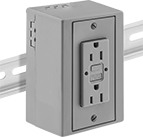
    Bring power closer to where you need it by mounting connectors to DIN rail.
    GFCI Female Receptacles
    Image of ProductInUse. Female Receptacle. Front orientation. Power Connectors. DIN-Rail-Mount Straight-Blade Connectors, GFCI Female Receptacles, Duplex.

    Female Receptacle

    Protect people and equipment from electric shock. These receptacles have a GFCI to cut power instantly when they detect a fault.
    NEMA
    Type
    Voltage,
    V AC
    Current,
    amp
    Certification
    Each
    Duplex
    5-20
    12520C-UL Listed, CSA Certified, UL Listed
    7656T130000000
     

    Plug-Base Circuit Breakers

    Image of Product. Front orientation. Circuit Breakers. Plug-Base Circuit Breakers.
    Replace any Edison-base fuse with these resettable circuit breakers. They are thermal, so they trip when heat is generated by overload current.
    Breakthrough Current @ Voltage—Breakthrough current is the maximum current that the circuit breaker can safely stop in the event of a short circuit.
    Current,
    A
    Voltage,
    V AC
    Mfr. Equiv.
    Fuse
    Breakthrough Current
    @ Voltage
    Mounting
    Location
    Certification
    Each
    Push-Button Style
     
    Thermal
    20120T, TL, W5,000 amp @ 120V ACFuse PanelUL Listed
    7075K3000000
     

    AFCI/GFCI Straight-Blade Connectors

    Minimize the risk of electric shock and electrical fires with a single connector. These connectors interrupt when an arc fault or ground fault is detected. All have internal shutters to prevent the insertion of foreign objects and accidental contact with power.
    Outlet-Box-Mount Female Receptacles
    Image of Product. Front orientation. Power Connectors. AFCI/GFCI Straight-Blade Connectors.
    Internal Shutter—Keep out foreign objects and avoid accidental contact with power.
    Manual Reset—Prevent unexpected start-up by cutting electricity until you press a reset button. Choose these connectors for job sites, workshops, and outdoor areas where moisture and equipment faults are common.
    Power Indicator—A light appears when the connector has power.
    NEMA
    Type
    Voltage,
    V AC
    Current,
    amp
    Shutter
    Location
    Reset
    Type
    Light Type
    Housing
    Material
    Certification
    Color
    Each
    Duplex
    5-20
    12520InternalManualPower IndicatorPlasticCSA Certified, UL Listed
    White1380N21000000
     

    GFCI Extension Cords

    Image of Product. Front orientation. Extension Cords. GFCI Extension Cords, Inline GFCI.

    Inline GFCI

    Protect people and equipment from electric shock. These extension cords have a GFCI to cut power instantly when they detect a fault. They work even if you plug the cord into an outlet that doesn't have a GFCI.
    Inline GFCI—The GFCI sits along the cord for easy access when you need to reset it. However, it doesn't protect the length of cord between the outlet and the GFCI.
    Manual Reset—Prevent unexpected start-up by cutting electricity until you press a reset button. Choose these cords for job sites, workshops, and outdoor areas where moisture and equipment faults are common.
    Power Indicator—A light indicates that power is flowing through the cord.
    Lg.,
    ft.
    Color
    AWG
    Current,
    amp
    Cable
    Designation
    For Use
    Outdoors
    Light Indicator
    Type
    Certification
    Each
    NEMA 5-20 Plug × Socket—120V AC
     
    Inline GFCI—Manual Reset
    2Yellow12
    20SJTW
    YesCSA Certified, UL Listed
    7348K53000000
    2Yellow12
    20SJTW
    YesPowerC-UL Listed, UL Listed
    73495K2500000
    25Yellow12
    20SJTW
    Yes7348K59000000
     
    NEMA 6-20 Plug × Socket—240V AC
     
    Inline GFCI—Manual Reset
    6Yellow12
    20SJTW
    YesCSA Certified, UL Listed
    7348K56000000
     

    Washdown Turn-Lock Connectors

    When mated, connectors are protected against corrosion and washdowns. All have a multiple-ring seal and rubber housing to keep out liquid. They resist heat, oil, and chemicals. A quarter turn locks them in place to remain secure in high-vibration applications and prevent accidental disconnection.
    Plugs mate with female receptacles and sockets with an attached cover. Male receptacles mate with sockets without an attached cover.
    GFCI Outlet-Box-Mount Female Receptacles with Attached Cover
    Image of Product. Front orientation. Power Connectors. Washdown Turn-Lock Connectors, GFCI Outlet-Box-Mount Female Receptacles with Attached Cover, Single.

    Single

    Protect people and equipment from electric shock. These receptacles have a GFCI to cut power instantly when they detect a fault.
    Rubber Housing—Protect connectors from damage caused by drops and impact.
    NEMA
    Type
    Voltage,
    V AC
    Current,
    amp
    Housing
    Material
    Color
    Enclosure Rating
    Each
    Single
    L5-20
    12520RubberYellowIP67, NEMA 6P, NEMA 12
    69435K6830000000
     

    Extension Cord ELCI Converters

    Image of Product. Front orientation. Extension Cord Circuit Interrupter Converters. Extension Cord ELCI Converters.
    Prevent shocks from extension cords connected to boats, RVs, and other large electrical systems. These ELCI (equipment leakage circuit interrupters) converters monitor the flow of current to and from an electrical system. If they detect an imbalance, they cut off the power. They’re similar to GFCI converters, but they monitor an entire system rather than one device. They also tolerate a higher level of imbalance before they trip. These converters have a manual reset to keep equipment from starting unexpectedly.
    For Cable OD
    Reset
    Type
    Current,
    amp
    Voltage, V AC
    Material
    Certification
    Color
    Each
    Inline ELCI
    5/16" to 7/16"Manual20120/240Polycarbonate
    UL Listed, CSA Certified
    Black5491N11000000
     

    Impact-Resistant Automatic-Wind Extension Cord Reels
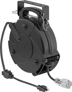
    Image of Product. Front orientation. Extension Cord Reels. Impact-Resistant Automatic-Wind Extension Cord Reels, Socket, 1 Outlet.

    Socket

    1 Outlet

    Image of Specification. NEMA 5-20 Socket. Front orientation. NEMA 5-20. Impact-Resistant Automatic-Wind Extension Cord Reels.

    NEMA

    5-20

    Socket

    Image of Specification. NEMA 5-20 Plug. Front orientation. NEMA 5-20. Impact-Resistant Automatic-Wind Extension Cord Reels.

    NEMA

    5-20

    Plug

    Made of impact-resistant plastic, these reels are more durable than other automatic-wind cord reels. They have a ratchet to hold the extension cord in place at any length; a quick pull releases the cord and the spring-driven winding mechanism retracts it. A resettable circuit breaker prevents overload damage. Mount reels to a wall or ceiling with the quick-release mounting bracket. The included extension cord resists oil and water.
    Extension Cord
    Power
    Cord
    Stationary
    Mounting Bracket
    No. of
    Outlets
    Lg.,
    ft.
    Wire Ga.
    (AWG)
    Industry
    Designation
    Color
    Lg.,
    ft.
    Wire Ga.
    (AWG)
    Winding
    Method
    Housing
    Material
    Current,
    amp
    Voltage,
    V AC
    Electrical Protection
    Type
    Lg.
    Wd.
    Ht.
    Features
    Certification
    Color
    Each
    Extension Cord with NEMA 5-20 Socket and Power Cord with NEMA 5-20 Plug
    13612
    SJTOW
    Yellow312
    AutomaticPlastic20120Circuit Breaker11 1/2"4 1/2"14"Carrying Handle, Quick-Release Mounting Bracket, RatchetUL Listed, C-UL Listed
    Black4804K170000000
    14512
    SJTOW
    Black312
    AutomaticPlastic20120Circuit Breaker13 1/2"5 1/2"15 1/2"Carrying Handle, Quick-Release Mounting Bracket, RatchetETL Listed, C-ETL Listed
    Black4804K13000000
     

    GFCI Straight-Blade Connectors

    Protect people and equipment from electric shock. These connectors have a GFCI to cut power instantly when they detect a fault.
    Outlet-Box-Mount Female Receptacles
    Image of Product. Front orientation. Power Connectors. GFCI Straight-Blade Connectors.
    Internal Shutter—Keep out foreign objects and avoid accidental contact with power.
    Manual Reset—Prevent unexpected start-up by cutting electricity until you press a reset button. Choose these connectors for job sites, workshops, and outdoor areas where moisture and equipment faults are common.
    Power Indicator—A light appears when the connector has power.
    NEMA
    Type
    Voltage,
    V AC
    Current,
    amp
    Shutter
    Location
    Reset
    Type
    Light Type
    Housing
    Material
    Certification
    Choose a Color
    Each
    Duplex
    5-20
    12520ManualPlasticC-UL Listed, UL Listed
    Brown, Ivory, White7160K74000000
    5-20
    12520InternalManualPower IndicatorPlasticCSA Certified, UL Listed
    Ivory, White7160K8200000
     

    Weather-Resistant GFCI Straight-Blade Connectors
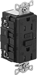
    Suitable for use outdoors, these receptacles can be used in wet and damp environments. They keep personnel safe from electric shock by adding ground fault protection. Internal shutters prevent the insertion of foreign objects and accidental contact with power.
    Outlet-Box-Mount Female Receptacles
    Image of Product. Front orientation. Power Connectors. Weather-Resistant GFCI Straight-Blade Connectors.
    Internal Shutter—Keep out foreign objects and avoid accidental contact with power.
    Manual Reset—Prevent unexpected start-up by cutting electricity until you press a reset button. Choose these connectors for job sites, workshops, and outdoor areas where moisture and equipment faults are common.
    NEMA
    Type
    Voltage,
    V AC
    Current,
    amp
    Shutter
    Location
    Reset
    Type
    Housing
    Material
    Certification
    Choose a Color
    Each
    Duplex
    5-20
    12520InternalManualPlasticCSA Certified, UL Listed
    Almond, Black, Brown, Gray, Ivory, Red, White7160K22000000
     

    Washdown Straight-Blade Connectors

    A multiple-ring seal and rubber housing protect these connectors from frequent washdowns. IP and NEMA rated, they seal out water and dust when mated, even if briefly submerged.
    Plugs mate with female receptacles and sockets with an attached cover. Male receptacles mate with sockets without an attached cover.
    GFCI Surface-Mount Female Receptacles with Attached Cover
    Image of Product. Front orientation. Power Connectors. Washdown Straight-Blade Connectors, GFCI Surface-Mount Female Receptacles with Attached Cover, Duplex.

    Duplex

    Manual Reset—Prevent unexpected start-up by cutting electricity until you press a reset button. Choose these connectors for job sites, workshops, and outdoor areas where moisture and equipment faults are common.
    Rubber Housing—Protect connectors from damage caused by drops and impact.
    NEMA
    Type
    Voltage,
    V AC
    Current,
    amp
    Reset
    Type
    Housing
    Material
    Enclosure Rating
    Certification
    Color
    Each
    Duplex
    5-20
    12520ManualRubberIP67, NEMA 6P, NEMA 12
    CSA Certified, UL Listed
    Yellow7140K850000000
     

    GFCI Snug-Fit Straight-Blade Connectors
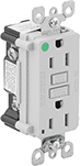
    Keep personnel safe from electric shock by adding ground fault protection. Also known as hospital-grade connectors, they're marked with a green dot. These connectors have an extra-tight fit when mated to remain secure in high-vibration environments.
    Outlet-Box-Mount Female Receptacles
    Image of Product. Front orientation. Power Connectors. GFCI Snug-Fit Straight-Blade Connectors.
    Manual Reset—Prevent unexpected start-up by cutting electricity until you press a reset button. Choose these connectors for job sites, workshops, and outdoor areas where moisture and equipment faults are common.
    Power Indicator—A light appears when the connector has power.
    NEMA
    Type
    Voltage,
    V AC
    Current,
    amp
    Reset
    Type
    Light Type
    Housing
    Material
    Certification
    Choose a Color
    Each
    Duplex
    5-20
    12520ManualPower IndicatorPlasticCSA Certified, UL Listed
    Brown, Ivory, White7160K76000000
     

    Outlet Strips

    Provide power to multiple devices with these outlet strips. A circuit breaker prevents damage from current overload and short circuits.
    Outlet Strips
    Image of Product. Bottom orientation. Outlet Strips. Outlet Strips.
    Image of Specification. NEMA 5-15 Socket. Front orientation. NEMA 5-15. Outlet Strips.
    Image of Specification. NEMA 5-20 Socket. Front orientation. NEMA 5-20. Outlet Strips.
    Image of Specification. NEMA 5-20 Plug. Front orientation. NEMA 5-20. Outlet Strips.
    Image of Specification. NEMA L5-20 Plug. Front orientation. NEMA L5-20. Outlet Strips.

    NEMA

    5-15

    Socket

    NEMA

    5-20

    Socket

    NEMA

    5-20

    Plug

    NEMA

    L5-20

    Plug

    Mounting Clips—Fasten mounting clips to a surface, and snap the channel on the back of outlet strips into the clips.
    Strips
    Replacement
    Outlet Strip Mounts
    No. of
    Sockets
    Total No.
    of Outlets
    NEMA
    5-15
    NEMA
    5-20
    Outlet
    Ctr.-to-Ctr.
    Cord Lg.,
    ft.
    Current,
    amp
    Voltage,
    V AC
    Features
    Material
    Electrical Protection
    Type
    Includes
    Certification
    Each
    Pkg.
    Qty.
    Pkg.
    NEMA 5-15 and NEMA 5-20 Sockets with NEMA 5-20 Plug
    242222 3/4"1520125Lighted Power SwitchAluminum
    Circuit BreakerMounting ClipsUL Listed, C-UL Listed
    71515K170000000———0
     
    NEMA 5-20 Socket with NEMA 5-20 Plug
    441 1/2"620125Lighted Power SwitchAluminum
    Circuit BreakerMounting ClipsUL Listed, C-UL Listed
    71515K3100000037361K21000000
    441 1/2"1520125Lighted Power SwitchAluminum
    Circuit BreakerMounting ClipsUL Listed, C-UL Listed
    71515K3200000037361K2100000
    661 1/2"620125Lighted Power SwitchAluminum
    Circuit BreakerMounting ClipsUL Listed, C-UL Listed
    71515K3300000037361K2100000
    661 1/2"1520125Lighted Power SwitchAluminum
    Circuit BreakerMounting ClipsUL Listed, C-UL Listed
    71515K3400000037361K2100000
     
    NEMA 5-15 and NEMA 5-20 Socket with NEMA L5-20 Plug
    242222 3/4"1520125Lighted Power SwitchAluminum
    Circuit BreakerMounting ClipsUL Listed, C-UL Listed
    71515K18000000———0
     

    GFCI Outlet Strips

    Image of Product. With Four Outlets and Straight Plug. Front orientation. Total of 4 Outlets. GFCI Outlet Strips, Straight End.

    With Four Outlets and

    Straight Plug

    Image of Specification. NEMA 5-20 Socket. Front orientation. NEMA 5-20. GFCI Outlet Strips.

    NEMA

    5-20

    Socket

    Image of Specification. NEMA 5-20 Plug. Front orientation. NEMA 5-20. GFCI Outlet Strips.

    NEMA

    5-20

    Plug

    Keep personnel safe from electric shock with ground fault protection. These outlet strips have a manual reset to prevent equipment from starting up unexpectedly after ground is established.
    Flip-Down Cover—Flip-down covers protect outlets from dust when not in use.
    Total No.
    of Outlets
    Outlet Ctr.-to-Ctr.
    (No. of)
    Cord Lg.,
    ft.
    Current,
    amp
    Voltage,
    V AC
    Features
    Material
    Electrical
    Protection Type
    Reset
    Type
    Certification
    Color
    Each
    NEMA 5-20 Socket with NEMA 5-20 Plug
     
    Straight End
    41 1/2" (4)620125Flip-Down CoverPolybutyleneGFCIManualUL Listed
    Yellow7048K370000000
     

    Controlled-Automatic-Wind Extension Cord Reels
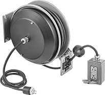
    Image of Product. Front orientation. Extension Cord Reels. Controlled-Automatic-Wind Extension Cord Reels , Socket, 2 Outlets.

    Socket

    2 Outlets

    Image of Specification. NEMA 5-20 Socket. Front orientation. NEMA 5-20. Controlled-Automatic-Wind Extension Cord Reels .

    NEMA

    5-20

    Socket

    Image of Specification. NEMA 5-20 Plug. Front orientation. NEMA 5-20. Controlled-Automatic-Wind Extension Cord Reels .

    NEMA

    5-20

    Plug

    Controlled winding prevents the cord from whipping at the end, making winding safer and extending the life of the cord and reel. These reels also have a ratchet to hold the extension cord in place at any length; a quick pull releases the cord and the spring-driven winding mechanism retracts it. An adjustable ball lock controls how much cord retracts into the reel. They have an adjustable arm so the cord can be accessed from any position around the reel.
    Circuit Breaker—Reels with a circuit breaker prevent overload damage.
    Extension Cord
    Power
    Cord
    Stationary
    Mounting Bracket
    No. of
    Outlets
    Lg.,
    ft.
    Wire Ga.
    (AWG)
    Industry
    Designation
    Lg.,
    ft.
    Wire Ga.
    (AWG)
    Winding
    Method
    Housing
    Material
    Current,
    amp
    Voltage,
    V AC
    Electrical Protection
    Type
    GFCI
    Location
    Lg.
    Wd.
    Ht.
    Features
    Certification
    Color
    Each
    Extension Cord with NEMA 5-20 Socket and Power Cord with NEMA 5-20 Plug
    25012
    SJO512
    AutomaticSteel20120Circuit Breaker, GFCISocket13 1/2"8 1/2"14 7/8"Adjustable Rubber Cord Stop, Mounting Bracket with Adjustable Arm, RatchetUL Listed
    Blue2781K30000000
    210012
    SJO512
    AutomaticSteel20120Circuit Breaker, GFCISocket24"10 1/4"25 1/2"Adjustable Rubber Cord Stop, Mounting Bracket with Adjustable Arm, RatchetBlue2781K600000000
     

    Harsh Environment Automatic-Wind Extension Cord Reels
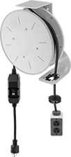
    Image of Product. Stationary Mount with Socket and Inline GFCI. Front orientation. Socket. Harsh Environment Automatic-Wind Extension Cord Reels , Stationary Mounting Bracket, Inline GFCI.
    Image of Product. Swing Out-Mount with Socket and Inline GFCI. Front orientation. Socket. Harsh Environment Automatic-Wind Extension Cord Reels , Swing-Out Mounting Bracket, Inline GFCI.

    Stationary Mount

    with Socket and

    Inline GFCI

    Swing Out-Mount

    with Socket and

    Inline GFCI

    Image of Specification. NEMA 5-20 Socket. Front orientation. NEMA 5-20. Harsh Environment Automatic-Wind Extension Cord Reels .

    NEMA

    5-20

    Socket

    Image of Specification. NEMA 5-20 Plug. Front orientation. NEMA 5-20. Harsh Environment Automatic-Wind Extension Cord Reels .

    NEMA

    5-20

    Plug

    Intended to withstand demanding applications, these reels have a steel housing and an oil- and water-resistant extension cord. The automatic take-up feature maintains constant tension on the extension cord as the spring-driven winding mechanism retracts it. An adjustable ball lock controls how much cord retracts into the reel.
    Swing-Out Mounting Bracket—Reels with a swing out-mount bracket dispense cord at any angle.
    Extension Cord
    Power
    Cord
    Stationary
    Mounting Bracket
    Swing-Out
    Mounting Bracket
    No. of
    Outlets
    Lg.,
    ft.
    Wire Ga.
    (AWG)
    Industry
    Designation
    Lg.,
    ft.
    Wire Ga.
    (AWG)
    Winding
    Method
    Housing
    Material
    Current,
    amp
    Voltage,
    V AC
    Electrical
    Protection Type
    GFCI
    Location
    Lg.
    Wd.
    Ht.
    Features
    Certification
    Color
    Each
    Each
    Extension Cord with NEMA 5-20 Socket and Power Cord with NEMA 5-20 Plug
    22512
    SJOW
    612
    AutomaticSteel20120GFCIInline12"7 3/4"13 7/8"Adjustable Ball Lock, Adjustable Cord Tension, Automatic Take-Up, Mounting Bracket, Slip RingUL Listed
    Yellow74705K730000000———0
    25012
    SJOW
    612
    AutomaticSteel20120GFCIInline12"7 3/4"13 7/8"Adjustable Ball Lock, Adjustable Cord Tension, Automatic Take-Up, Mounting Bracket, Slip RingUL Listed
    Yellow74705K74000000———0
    42512
    SJOW
    612
    AutomaticSteel20120GFCIInline12"7 3/4"13 7/8"Adjustable Ball Lock, Adjustable Cord Tension, Automatic Take-Up, Mounting Bracket, Slip RingUL Listed
    Yellow———07608K130000000
    45012
    SJOW
    612
    AutomaticSteel20120GFCIInline12"7 3/4"13 7/8"Adjustable Ball Lock, Adjustable Cord Tension, Automatic Take-Up, Mounting Bracket, Slip RingUL Listed
    Yellow———07608K22000000
     
    Extension Cord Reel Bases

    Cabinet-Mount Outlet Strips

    Image of Product. Front orientation. Outlet Strips. Cabinet-Mount Outlet Strips.
    Image of Specification. NEMA 5-20 Socket. Front orientation. NEMA 5-20. Cabinet-Mount Outlet Strips.

    NEMA

    5-20

    Socket

    Image of Specification. NEMA 5-20 Plug. Front orientation. NEMA 5-20. Cabinet-Mount Outlet Strips.

    NEMA

    5-20

    Plug

    Install these extra-long strips onto the frame of an electrical cabinet. Screw the included mounting clips to the cabinet and snap the strips into the clips.
    Strips
    Replacement
    Outlet Strip Mounts
    No. of
    Outlets
    Outlet
    Ctr.-to-Ctr.
    Cord Lg.,
    ft.
    Current,
    amp
    Voltage,
    V AC
    Material
    Electrical Protection
    Type
    Includes
    Certification
    Color
    Each
    Pkg.
    Qty.
    Pkg.
    NEMA 5-20 Socket with NEMA 5-20 Plug
    104"620125Aluminum
    Circuit BreakerMounting Clips, Mounting ScrewsUL Listed
    Gray71195K54000000037361K891000000
    104"1520125Aluminum
    Circuit BreakerMounting Clips, Mounting ScrewsUL Listed
    Gray71195K7400000037361K89100000
    116"620125Aluminum
    Circuit BreakerMounting Clips, Mounting ScrewsUL Listed
    Gray71195K5500000037361K89100000
    116"1520125Aluminum
    Circuit BreakerMounting Clips, Mounting ScrewsUL Listed
    Gray71195K7500000037361K89100000
    126"620125Aluminum
    Circuit BreakerMounting Clips, Mounting ScrewsUL Listed
    Gray71195K5600000037361K89100000
    126"1520125Aluminum
    Circuit BreakerMounting Clips, Mounting ScrewsUL Listed
    Gray71195K7600000037361K89100000
     
    back to top