


Filter by
Bearing Material
OD
Performance
ID
Dynamic Radial Load Capacity @ Speed
P Max
Lubrication
Plain Bearing Type
For Housing ID
Bearing Type
Backing Material
Shaft Mount Type

For Load Direction
Minimum Temperature
Export Control Classification Number (ECCN)
DFARS Specialty Metals
For Use In

About Sleeve Bearings
Choose a sleeve bearing that matches your load and speed requirements and that's right for your environment.
Dry-Running Sleeve Bearings
 |
Made of naturally slippery plastic so you’ll never have to add lubricant. They’re ideal for clean environments where you need to prevent oil drips or graphite flakes. Compared to metal bearings, they are lighter and will never rust.
With no moving parts, sleeve bearings are the simplest way to support the load of a rotating shaft while reducing friction. Also known as plain bearings.
Extreme-Load Ultra-Chemical-Resistant Fiberglass-Backed PTFE—Our strongest PTFE bearings. They’re ideal for heavy loads thanks to a backing layer made of fiberglass. The PTFE core is unaffected by the harsh fluids that other plastics can't handle, including all strong acids and bases.
Each | |||||||||||
|---|---|---|---|---|---|---|---|---|---|---|---|
For Shaft Dia. | For Housing ID | Lg. | Dynamic Radial Load Cap. @ Speed | Color | Temp. Range, ° F | 1-24 | 25-99 | 100-Up | |||
Extreme-Load Ultra-Chemical-Resistant Fiberglass-Backed PTFE | |||||||||||
| 1/2" | 5/8" | 1/2" | 1,250 lb. @ 120 rpm | Gray | -55 to 280 | 6365K401 | 00000 | 00000 | 00000 | ||
| 1/2" | 5/8" | 1" | 2,500 lb. @ 120 rpm | Gray | -55 to 280 | 6365K402 | 0000 | 0000 | 0000 | ||
| 1/2" | 3/4" | 3/4" | 1,850 lb. @ 120 rpm | Gray | -55 to 280 | 6365K403 | 0000 | 0000 | 0000 | ||
| 1/2" | 3/4" | 1" | 2,500 lb. @ 120 rpm | Gray | -55 to 280 | 6365K404 | 0000 | 0000 | 0000 | ||
| 5/8" | 7/8" | 3/4" | 3,750 lb. @ 60 rpm | Gray | -55 to 280 | 6365K405 | 0000 | 0000 | 0000 | ||
| 5/8" | 7/8" | 1" | 5,050 lb. @ 60 rpm | Gray | -55 to 280 | 6365K406 | 0000 | 0000 | 0000 | ||
| 3/4" | 7/8" | 3/4" | 3,750 lb. @ 60 rpm | Gray | -55 to 280 | 6365K407 | 0000 | 0000 | 0000 | ||
| 3/4" | 7/8" | 1 1/4" | 6,300 lb. @ 60 rpm | Gray | -55 to 280 | 6365K408 | 0000 | 0000 | 0000 | ||
| 3/4" | 1" | 1" | 5,050 lb. @ 60 rpm | Gray | -55 to 280 | 6365K409 | 0000 | 0000 | 0000 | ||
| 1" | 1 1/4" | 1" | 5,050 lb. @ 60 rpm | Gray | -55 to 280 | 6365K41 | 00000 | 0000 | 0000 | ||
| 1" | 1 1/4" | 1 1/2" | 7,550 lb. @ 60 rpm | Gray | -55 to 280 | 6365K411 | 00000 | 00000 | 00000 | ||
| 1" | 1 1/4" | 2" | 10,100 lb. @ 60 rpm | Gray | -55 to 280 | 6365K412 | 00000 | 00000 | 00000 | ||
| 1 1/4" | 1 1/2" | 2" | 20,200 lb. @ 30 rpm | Gray | -55 to 280 | 6365K413 | 00000 | 00000 | 00000 | ||
| 1 1/4" | 1 1/2" | 3" | 30,350 lb. @ 30 rpm | Gray | -55 to 280 | 6365K414 | 00000 | 00000 | 00000 | ||
| 1 1/2" | 1 3/4" | 2" | 20,200 lb. @ 30 rpm | Gray | -55 to 280 | 6365K415 | 00000 | 00000 | 00000 | ||
| 2" | 2 1/4" | 1 1/2" | 15,150 lb. @ 30 rpm | Gray | -55 to 280 | 6365K416 | 00000 | 00000 | 00000 | ||
| 2" | 2 1/4" | 3" | 30,350 lb. @ 30 rpm | Gray | -55 to 280 | 6365K417 | 00000 | 00000 | 00000 | ||
Electrical Insulating Unthreaded Spacers
 |
Lg. | For Screw Size | ID | Dielectric Strength, V/mil | Temp. Range, ° F | Pkg. Qty. | Pkg. | |||
|---|---|---|---|---|---|---|---|---|---|
Garolite | |||||||||
3/16" OD | |||||||||
| 3/16" | No. 4 | 0.115" | 400 | 0 to 300 | 1 | 92273A003 | 00000 | ||
| 1/4" | No. 4 | 0.115" | 400 | 0 to 300 | 1 | 92273A005 | 0000 | ||
| 5/16" | No. 4 | 0.115" | 400 | 0 to 300 | 1 | 92273A007 | 0000 | ||
| 3/8" | No. 4 | 0.115" | 400 | 0 to 300 | 1 | 92273A009 | 0000 | ||
| 1/2" | No. 4 | 0.115" | 400 | 0 to 300 | 1 | 92273A011 | 0000 | ||
1/4" OD | |||||||||
| 3/16" | No. 4 | 0.115" | 400 | 0 to 300 | 1 | 92273A023 | 0000 | ||
| 3/16" | No. 6 | 0.140" | 400 | 0 to 300 | 1 | 92273A043 | 0000 | ||
| 1/4" | No. 4 | 0.115" | 400 | 0 to 300 | 1 | 92273A025 | 0000 | ||
| 1/4" | No. 6 | 0.140" | 400 | 0 to 300 | 1 | 92273A045 | 0000 | ||
| 5/16" | No. 4 | 0.115" | 400 | 0 to 300 | 1 | 92273A027 | 0000 | ||
| 5/16" | No. 6 | 0.140" | 400 | 0 to 300 | 1 | 92273A047 | 0000 | ||
| 3/8" | No. 4 | 0.115" | 400 | 0 to 300 | 1 | 92273A029 | 0000 | ||
| 3/8" | No. 6 | 0.140" | 400 | 0 to 300 | 1 | 92273A049 | 0000 | ||
| 1/2" | No. 4 | 0.115" | 400 | 0 to 300 | 1 | 92273A031 | 0000 | ||
| 1/2" | No. 6 | 0.140" | 400 | 0 to 300 | 1 | 92273A051 | 0000 | ||
| 1/2" | No. 8 | 0.167" | 400 | 0 to 300 | 1 | 92273A115 | 0000 | ||
| 3/4" | No. 6 | 0.140" | 400 | 0 to 300 | 1 | 92273A113 | 0000 | ||
| 3/4" | No. 8 | 0.167" | 400 | 0 to 300 | 1 | 92273A116 | 0000 | ||
| 1" | No. 6 | 0.140" | 400 | 0 to 300 | 1 | 92273A114 | 00000 | ||
| 1" | No. 8 | 0.167" | 400 | 0 to 300 | 1 | 92273A117 | 00000 | ||
5/16" OD | |||||||||
| 3/16" | No. 10 | 0.192" | 400 | 0 to 300 | 1 | 92273A063 | 0000 | ||
| 1/4" | No. 10 | 0.192" | 400 | 0 to 300 | 1 | 92273A065 | 0000 | ||
| 5/16" | No. 10 | 0.192" | 400 | 0 to 300 | 1 | 92273A067 | 0000 | ||
| 3/8" | No. 10 | 0.192" | 400 | 0 to 300 | 1 | 92273A069 | 0000 | ||
| 1/2" | No. 10 | 0.192" | 400 | 0 to 300 | 1 | 92273A071 | 0000 | ||
3/8" OD | |||||||||
| 1/4" | No. 10 | 0.192" | 400 | 0 to 300 | 1 | 92273A083 | 0000 | ||
| 3/8" | No. 10 | 0.192" | 400 | 0 to 300 | 1 | 92273A085 | 0000 | ||
| 1/2" | No. 10 | 0.192" | 400 | 0 to 300 | 1 | 92273A087 | 0000 | ||
| 3/4" | No. 10 | 0.192" | 400 | 0 to 300 | 1 | 92273A089 | 0000 | ||
| 1" | No. 10 | 0.192" | 400 | 0 to 300 | 1 | 92273A091 | 00000 | ||
| 1 1/2" | No. 10 | 0.192" | 400 | 0 to 300 | 1 | 92273A094 | 00000 | ||
1/2" OD | |||||||||
| 3/16" | No. 10 | 0.192" | 400 | 0 to 300 | 1 | 92273A102 | 0000 | ||
| 3/16" | 1/4" | 0.260" | 400 | 0 to 300 | 1 | 92273A122 | 0000 | ||
| 1/4" | No. 10 | 0.192" | 400 | 0 to 300 | 1 | 92273A104 | 0000 | ||
| 1/4" | 1/4" | 0.260" | 400 | 0 to 300 | 1 | 92273A124 | 0000 | ||
| 5/16" | 1/4" | 0.260" | 400 | 0 to 300 | 1 | 92273A126 | 0000 | ||
| 3/8" | No. 10 | 0.192" | 400 | 0 to 300 | 1 | 92273A106 | 0000 | ||
| 3/8" | 1/4" | 0.260" | 400 | 0 to 300 | 1 | 92273A128 | 0000 | ||
| 1/2" | No. 10 | 0.192" | 400 | 0 to 300 | 1 | 92273A108 | 0000 | ||
| 1/2" | 1/4" | 0.260" | 400 | 0 to 300 | 1 | 92273A132 | 0000 | ||
| 5/8" | 1/4" | 0.260" | 400 | 0 to 300 | 1 | 92273A134 | 0000 | ||
| 3/4" | No. 10 | 0.192" | 400 | 0 to 300 | 1 | 92273A110 | 0000 | ||
| 3/4" | 1/4" | 0.260" | 400 | 0 to 300 | 1 | 92273A136 | 0000 | ||
| 7/8" | 1/4" | 0.260" | 400 | 0 to 300 | 1 | 92273A138 | 0000 | ||
| 1" | No. 10 | 0.192" | 400 | 0 to 300 | 1 | 92273A112 | 0000 | ||
| 1" | 1/4" | 0.260" | 400 | 0 to 300 | 1 | 92273A140 | 00000 | ||
| 1 1/2" | 1/4" | 0.260" | 400 | 0 to 300 | 1 | 92273A142 | 00000 | ||
| 1 3/4" | 1/4" | 0.260" | 400 | 0 to 300 | 1 | 92273A144 | 00000 | ||
| 2" | 1/4" | 0.260" | 400 | 0 to 300 | 1 | 92273A146 | 00000 | ||
3/4" OD | |||||||||
| 1/2" | 1/4" | 0.260" | 400 | 0 to 300 | 1 | 92273A152 | 0000 | ||
| 1/2" | 5/16" | 0.325" | 400 | 0 to 300 | 1 | 92273A172 | 0000 | ||
| 1/2" | 3/8" | 0.385" | 400 | 0 to 300 | 1 | 92273A192 | 0000 | ||
| 3/4" | 1/4" | 0.260" | 400 | 0 to 300 | 1 | 92273A154 | 00000 | ||
| 3/4" | 5/16" | 0.325" | 400 | 0 to 300 | 1 | 92273A174 | 0000 | ||
| 3/4" | 3/8" | 0.385" | 400 | 0 to 300 | 1 | 92273A194 | 0000 | ||
| 1" | 1/4" | 0.260" | 400 | 0 to 300 | 1 | 92273A156 | 00000 | ||
| 1" | 5/16" | 0.325" | 400 | 0 to 300 | 1 | 92273A176 | 00000 | ||
| 1" | 3/8" | 0.385" | 400 | 0 to 300 | 1 | 92273A196 | 00000 | ||
| 1 1/2" | 5/16" | 0.325" | 400 | 0 to 300 | 1 | 92273A178 | 00000 | ||
| 1 1/2" | 3/8" | 0.385" | 400 | 0 to 300 | 1 | 92273A198 | 00000 | ||
| 1 3/4" | 1/4" | 0.260" | 400 | 0 to 300 | 1 | 92273A158 | 00000 | ||
| 1 3/4" | 5/16" | 0.325" | 400 | 0 to 300 | 1 | 92273A180 | 00000 | ||
| 1 3/4" | 3/8" | 0.385" | 400 | 0 to 300 | 1 | 92273A201 | 00000 | ||
| 2" | 1/4" | 0.260" | 400 | 0 to 300 | 1 | 92273A160 | 00000 | ||
| 2" | 5/16" | 0.325" | 400 | 0 to 300 | 1 | 92273A182 | 00000 | ||
| 2" | 3/8" | 0.385" | 400 | 0 to 300 | 1 | 92273A204 | 00000 | ||
| 2 1/2" | 3/8" | 0.385" | 400 | 0 to 300 | 1 | 92273A207 | 00000 | ||
| 2 3/4" | 3/8" | 0.385" | 400 | 0 to 300 | 1 | 92273A209 | 00000 | ||
| 3" | 3/8" | 0.385" | 400 | 0 to 300 | 1 | 92273A212 | 00000 | ||
1" OD | |||||||||
| 1/2" | 1/2" | 0.510" | 400 | 0 to 300 | 1 | 92273A222 | 0000 | ||
| 3/4" | 1/2" | 0.510" | 400 | 0 to 300 | 1 | 92273A224 | 00000 | ||
| 1" | 1/2" | 0.510" | 400 | 0 to 300 | 1 | 92273A226 | 00000 | ||
| 1 1/2" | 1/2" | 0.510" | 400 | 0 to 300 | 1 | 92273A228 | 00000 | ||
| 1 3/4" | 1/2" | 0.510" | 400 | 0 to 300 | 1 | 92273A230 | 00000 | ||
| 2" | 1/2" | 0.510" | 400 | 0 to 300 | 1 | 92273A233 | 00000 | ||
| 2 1/2" | 1/2" | 0.510" | 400 | 0 to 300 | 1 | 92273A236 | 00000 | ||
| 2 3/4" | 1/2" | 0.510" | 400 | 0 to 300 | 1 | 92273A239 | 00000 | ||
| 3" | 1/2" | 0.510" | 400 | 0 to 300 | 1 | 92273A242 | 00000 | ||
Electrical Insulating Female Threaded Standoffs
Hex
 |
 |
Threaded on Both Ends |
High-Strength Fiberglass-Reinforced Plastic—A lightweight alternative to stainless steel, these have the best strength-to-weight ratio of all our nonmetal standoffs.
Round
 | |
Threaded on Both Ends |
High-Strength Fiberglass-Reinforced Plastic—A lightweight alternative to stainless steel, these have the best strength-to-weight ratio of all our nonmetal standoffs.
Lg. | OD | Threading | Min. Thread Lg. | Dielectric Strength, V/mil | Voltage Rating, V | Temp. Range, ° F | Each | |||
|---|---|---|---|---|---|---|---|---|---|---|
High-Strength Fiberglass-Reinforced Plastic | ||||||||||
3/8"-16 Threads | ||||||||||
| 1 3/8" | 1 3/4" | Threaded on Both Ends | 3/8" | 350 | 1,500 | — | 3314A2 | 00000 | ||
| 1 3/4" | 2" | Threaded on Both Ends | 3/8" | 350 | 2,000 | -40 to 266 | 3314A3 | 00000 | ||
| 2" | 2" | Threaded on Both Ends | 9/16" | 350 | 2,300 | -40 to 266 | 3314A1 | 00000 | ||
| 2 1/4" | 1 3/4" | Threaded on Both Ends | 9/16" | 350 | 2,700 | — | 3314A6 | 0000 | ||
Octagon
 |
|
Threaded on Both Ends |
High-Strength Fiberglass-Reinforced Plastic—A lightweight alternative to stainless steel, these have the best strength-to-weight ratio of all our nonmetal standoffs.
Lg. | Hex Size | Threading | Min. Thread Lg. | Dielectric Strength, V/mil | Voltage Rating, V | Each | |||
|---|---|---|---|---|---|---|---|---|---|
High-Strength Fiberglass-Reinforced Plastic | |||||||||
1/2"-13 Threads | |||||||||
| 3" | 2 1/2" | Threaded on Both Ends | 5/8" | 350 | 4,100 | 3314A4 | 000000 | ||
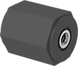
Electrical Insulating Linear Sleeve Bearings
Fixed Alignment
 |
0.001" Shaft Clearance—Bearings with 0.001" shaft clearance are less likely to bind on your shaft than bearings with 0.0005" shaft clearance.
Bearings | Retaining Rings | |||||||||||||||||
|---|---|---|---|---|---|---|---|---|---|---|---|---|---|---|---|---|---|---|
Temp., ° F | ||||||||||||||||||
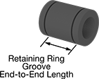
For Shaft Dia. | Shaft Clearance | Overall Lg. | OD | For Housing ID | With Retaining Ring Grooves | Retaining Ring Groove End-to-End Lg. | With End Seals | Dynamic Linear Load Cap. @ Speed | Static Load Cap., lb. | Min. | Max. | For Shaft Material | Each | Each | ||||
PTFE-Lined Fiberglass Bearings | ||||||||||||||||||
| 1/2" | 0.001" | 1 1/4" | 7/8" | 0.8750" to 0.8755" | Yes | 0.975" | No | 150 lb. @ 100 fpm | 3,100 | -400 | 375 | Aluminum, Stainless Steel | 8356K12 | 000000 | 9968K24 | 00000 | ||
| 5/8" | 0.001" | 1 1/2" | 1 1/8" | 1.1250" to 1.1255" | Yes | 1.116" | No | 250 lb. @ 100 fpm | 4,600 | -400 | 375 | Aluminum, Stainless Steel | 8356K13 | 00000 | 9968K25 | 0000 | ||
| 3/4" | 0.001" | 1 5/8" | 1 1/4" | 1.2500" to 1.2505" | Yes | 1.178" | No | 350 lb. @ 100 fpm | 6,100 | -400 | 375 | Aluminum, Stainless Steel | 8356K14 | 00000 | 9968K26 | 0000 | ||
| 1" | 0.001" | 2 1/4" | 1 9/16" | 1.5625" to 1.5630" | Yes | 1.765" | No | 600 lb. @ 100 fpm | 11,000 | -400 | 375 | Aluminum, Stainless Steel | 8356K15 | 00000 | 9968K27 | 0000 | ||
Press-In Threaded Inserts for Carbon Fiber, Fiberglass, and Garolite
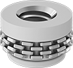 |
Add threads to dense composites without crushing or splitting them. Press these inserts into a drilled hole and the flexible metal teeth anchor them—no adhesives needed.
18-8 Stainless Steel and Nylon—With stainless steel threads and a nylon base, these inserts resist rust and mild chemicals.
Inserts | Installation Tools | |||||||||
|---|---|---|---|---|---|---|---|---|---|---|
Thread Size | Installed Lg. | Rows of Teeth | Drill Bit Size, mm | For Max. Hole Dia., mm | Each | Each | ||||
Standard Profile | ||||||||||
18-8 Stainless Steel and Nylon | ||||||||||
| 10-24 | 0.236" | 2 | 11.8 | 11.8 | 93907A101 | 00000 | 93913A101 | 000000 | ||
| 10-24 | 0.335" | 4 | 11.8 | 11.8 | 93907A102 | 0000 | 93913A101 | 00000 | ||
| 1/4"-20 | 0.197" | 1 | 11.8 | 11.8 | 93907A103 | 0000 | 93913A102 | 00000 | ||
| 1/4"-20 | 0.236" | 2 | 11.8 | 11.8 | 93907A104 | 0000 | 93913A102 | 00000 | ||
| 1/4"-20 | 0.315" | 4 | 11.8 | 11.8 | 93907A105 | 0000 | 93913A102 | 00000 | ||
| 1/4"-20 | 0.591" | 4 | 11.8 | 11.8 | 93907A106 | 0000 | 93913A102 | 00000 | ||
| M4 x 0.7 mm | 5 mm | 1 | 11.8 | 11.8 | 93918A101 | 0000 | 93913A103 | 00000 | ||
| M4 x 0.7 mm | 6 mm | 2 | 11.8 | 11.8 | 93918A102 | 0000 | 93913A103 | 00000 | ||
| M4 x 0.7 mm | 8.5 mm | 4 | 11.8 | 11.8 | 93918A103 | 0000 | 93913A103 | 00000 | ||
| M5 x 0.8 mm | 5 mm | 1 | 11.8 | 11.8 | 93918A104 | 0000 | 93913A104 | 00000 | ||
| M5 x 0.8 mm | 6 mm | 2 | 11.8 | 11.8 | 93918A105 | 0000 | 93913A104 | 00000 | ||
| M5 x 0.8 mm | 8.5 mm | 4 | 11.8 | 11.8 | 93918A106 | 0000 | 93913A104 | 00000 | ||
| M6 x 1 mm | 5 mm | 1 | 11.8 | 11.8 | 93918A107 | 0000 | 93913A105 | 00000 | ||
| M6 x 1 mm | 6 mm | 2 | 11.8 | 11.8 | 93918A108 | 0000 | 93913A105 | 00000 | ||
| M6 x 1 mm | 8.5 mm | 4 | 11.8 | 11.8 | 93918A109 | 0000 | 93913A105 | 00000 | ||
| M6 x 1 mm | 15 mm | 4 | 11.8 | 11.8 | 93918A110 | 0000 | 93913A105 | 00000 | ||
Tee-Nut Threaded Inserts for Fiberglass
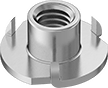 |
Reduce the risk of splitting or cracking fiberglass. These inserts have three short, thin prongs that won't dig too deep or wedge between layers of the material. Hammer them into a drilled hole and the wide flange distributes the load over a large area.
Zinc-Plated Steel—A step up from plain steel, the plating withstands occasional exposure to moisture.
Barrel | Flange | |||||||||||
|---|---|---|---|---|---|---|---|---|---|---|---|---|
Thread Size | Installed Lg. | Dia. | Lg. | Dia. | Thick. | Drill Bit Size | For Max. Hole Dia. | Pkg. Qty. | Pkg. | |||
Zinc-Plated Steel | ||||||||||||
| 8-32 | 0.289" | 0.22" | 1/4" | 1/2" | 0.04" | 7/32" | 0.219" | 100 | 90975A101 | 000000 | ||
| 10-32 | 0.227" | 0.243" | 3/16" | 1/2" | 0.04" | 1/4" | 0.250" | 100 | 90975A015 | 00000 | ||
| 10-32 | 0.500" | 0.243" | 3/8" | 1/2" | 0.04" | 1/4" | 0.250" | 25 | 90975A511 | 00000 | ||
| 1/4"-20 | 0.235" | 0.305" | 3/16" | 3/4" | 0.05" | 5/16" | 0.313" | 50 | 90975A071 | 00000 | ||
| M6 x 1 mm | 6.8 mm | 7.7 mm | 5.6 mm | 19.1 mm | 1.2 mm | 7.9 mm | 7.9 mm | 25 | 90975A411 | 00000 | ||
