


Body Material Body Material |
|---|
|
Set Point Set Point |
|---|
Connection Style Connection Style |
|---|
 |
| Threaded |
 |
| Socket Weld |
 |
| Compression |
Maximum Pressure Maximum Pressure |
|---|
|
Maximum Temperature Maximum Temperature |
|---|
|
Mounting Orientation Mounting Orientation |
|---|
|
Set Point Configuration Set Point Configuration |
|---|
|
Current Current |
|---|
Electrical Connection Type Electrical Connection Type |
|---|
|
Switch Starting Position Switch Starting Position |
|---|
DFARS (Defense Acquisition Regulations Supplement) DFARS (Defense AcquisitionRegulations Supplement) |
|---|
RoHS (Restriction of Hazardous Substances) RoHS (Restriction ofHazardous Substances) |
|---|
|
REACH (Registration, Evaluation, Authorization and Restriction of Chemicals) REACH (Registration,Evaluation, Authorization and Restriction of Chemicals) |
|---|
|
About Flowmeters and Totalizers
Flowmeters measure the rate of flow for a liquid or a gas. Totalizers measure the cumulative flow volume. Flowmeter/totalizers display both the flow rate and the cumulative flow volume.
More
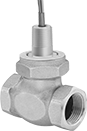
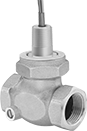
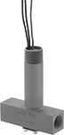
Compact Flow Switches for Water
These switches have a low-profile design to fit in water pipelines with limited clearance. They activate or deactivate equipment when the flow rate reaches your set point.
SPST-NO switches turn one circuit from “off” to “on” (normally open).
SPDT switches can be installed to turn one circuit from “off” to “on” (normally open) or from “on” to “off” (normally closed).
![]() For technical drawings and 3-D models, click on a part number.
For technical drawings and 3-D models, click on a part number.
| Pipe Size | Thread Type | Gender | Body Material | Max. Pressure | Temp. Range, °F | Voltage | Current | End-to-End Lg. | Choose a Set Point, gpm | Each | |
SPST-NO | |||||||||||
|---|---|---|---|---|---|---|---|---|---|---|---|
| 1/4 | NPT | Female | Polypropylene Plastic | 200 psi @ 70° F | 33° to 194° | 120V AC/ 240V AC | __ | 4 7/8" | 000000 | 000000 | |
| 3/8 | NPT | Male | Polypropylene Plastic | 125 psi @ 70° F | 33° to 212° | 120V AC | 0.2 A @ 120 V AC | 4" | 0000000 | 00000 | |
| Pipe Size | Thread Type | Gender | Body Material | Max. Pressure | Temp. Range, °F | Voltage | Current | Max. Current @ Max. Switching Voltage | Port-to-Port Lg. | Choose a Set Point, gpm | Each | |
SPST-NO | ||||||||||||
|---|---|---|---|---|---|---|---|---|---|---|---|---|
| 1/4 | NPT | Female | Polypropylene Plastic | 200 psi @ 70° F | 33° to 194° | 120V AC/ 240V AC | __ | 0.5 A @ 300 V AC; 0.7 A @ 350 V DC | 1 7/8" | 000000 | 000000 | |
| 3/4 | NPT | Female | Polypropylene Plastic | 100 psi @ 70° F | 0° to 210° | 120V AC/ 240V AC | 0.2 A @ 120 V AC | __ | 1 1/2" | 0.5 | 0000000 | 000000 |
SPDT | ||||||||||||
| 1/4 | NPT | Female | PPS Plastic | 250 psi @ 70° F | 32° to 225° | 120V AC/ 240V AC | 0.2 A @ 120 V AC | __ | 1 7/8" | 0000000 | 000000 | |
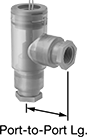
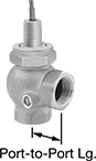
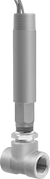
Compact Flow Switches for Oil
The low-profile metal body is designed for use in oil pipelines with limited clearance. These switches activate or deactivate equipment when the flow rate reaches your set point.
SPST-NO switches turn one circuit from “off” to “on” (normally open).
SPDT switches can be installed to turn one circuit from “off” to “on” (normally open) or from “on” to “off” (normally closed).
Switches with a 316 stainless steel body are more corrosion resistant than switches with a brass body.
![]() For technical drawings and 3-D models, click on a part number.
For technical drawings and 3-D models, click on a part number.

| Pipe Size | Thread Type | Gender | Body Material | Max. Pressure | Temp. Range, °F | Voltage | Current | End-to-End Lg. | Choose a Set Point, gpm | Each | |
| 3/8 | NPT | Male | Brass | 1500 psi @ 70° F | -20° to 275° | 120V AC 240V AC | 0.2 A @ 120 V AC | 3 7/16" | 000000 | 0000000 | |
| 3/8 | NPT | Male | 316 Stainless Steel | 1500 psi @ 70° F | -20° to 275° | 120V AC 240V AC | 0.2 A @ 120 V AC | 3 7/16" | 000000 | 000000 | |
| 1/2 | NPT | Male | Brass | 1500 psi @ 70° F | -20° to 275° | 120V AC 240V AC | 0.2 A @ 120 V AC | 4" | 000000 | 000000 |

Conduit | ||||||||||||||
|---|---|---|---|---|---|---|---|---|---|---|---|---|---|---|
| Pipe Size | Thread Type | Gender | Body Material | Max. Pressure | Temp. Range, °F | Voltage | Current | Trade Size | Thread Type | Gender | Port-to-Port Lg. | Choose a Set Point, gpm | Each | |
| 1/4 | NPT | Female | Brass | 1000 psi @ 70° F | -20° to 225° | 120V AC 240V AC | 0.2 A @ 120 V AC | 1/2 | NPT | Female | 2 1/16" | 000000 | 0000000 | |
| 1/4 | NPT | Female | Brass | 1000 psi @ 70° F | -20° to 225° | 120V AC 240V AC | 0.2 A @ 120 V AC | 1/2 | NPT | Female | 2 1/16" | 000000 | 000000 | |
Flow Switches for Water and Oil
These switches activate or deactivate equipment when the flow rate reaches your set point. They are single pole, double throw (SPDT) and can be installed to turn one circuit from “off” to “on” (normally open) or from “on” to “off” (normally closed).
Switches with a 316 stainless steel body are more corrosion resistant than switches with a bronze body.
![]() For technical drawings and 3-D models, click on a part number.
For technical drawings and 3-D models, click on a part number.
Conduit | |||||||||||||
|---|---|---|---|---|---|---|---|---|---|---|---|---|---|
| Pipe Size | Thread Type | Gender | Max. Pressure | Temp. Range, °F | Voltage | Current | Trade Size | Thread Type | Gender | End-to-End Lg. | Choose a Set Point, gpm | Each | |
Bronze Body | |||||||||||||
| 1 | NPT | Female | 400 psi @ 70° F | -20° to 300° | 120V AC/ 240V AC | 0.17 A @ 120 V AC | 1/2 | NPT | Male | 3 1/4" | 0000000 | 0000000 | |
| 1 1/4 | NPT | Female | 400 psi @ 70° F | -20° to 300° | 120V AC/ 240V AC | 0.17 A @ 120 V AC | 1/2 | NPT | Male | 4" | 0000000 | 000000 | |
| 1 1/2 | NPT | Female | 400 psi @ 70° F | -20° to 300° | 120V AC/ 240V AC | 0.17 A @ 120 V AC | 1/2 | NPT | Male | 4 1/2" | 0000000 | 000000 | |
| 2 | NPT | Female | 400 psi @ 70° F | -20° to 300° | 120V AC/ 240V AC | 0.17 A @ 120 V AC | 1/2 | NPT | Male | 5 3/8" | 0000000 | 000000 | |
316 Stainless Steel Body | |||||||||||||
| 1 | NPT | Female | 400 psi @ 70° F | -20° to 300° | 120V AC/ 240V AC | 0.17 A @ 120 V AC | 1/2 | NPT | Male | 3 1/4" | 0000000 | 000000 | |
| 1 1/4 | NPT | Female | 400 psi @ 70° F | -20° to 300° | 120V AC/ 240V AC | 0.17 A @ 120 V AC | 1/2 | NPT | Male | 4 1/2" | 0000000 | 00000000 | |
| 1 1/2 | NPT | Female | 400 psi @ 70° F | -20° to 300° | 120V AC/ 240V AC | 0.17 A @ 120 V AC | 1/2 | NPT | Male | 4 1/2" | 5 | 00000000 | 00000000 |
| 2 | NPT | Female | 400 psi @ 70° F | -20° to 300° | 120V AC/ 240V AC | 0.17 A @ 120 V AC | 1/2 | NPT | Male | 5 3/8" | 0000000 | 00000000 | |
Adjustable Flow Switches for Water and Oil
An adjustment screw lets you alter the set point to suit your application. These switches activate or deactivate equipment when the flow rate reaches your set point. All are single pole, double throw (SPDT) and can be installed to turn one circuit from “off” to “on” (normally open) or from “on” to “off” (normally closed).
![]() For technical drawings and 3-D models, click on a part number.
For technical drawings and 3-D models, click on a part number.
Hazardous Location Flow Switches for Water, Air, and Inert Gas
These switches are UL listed for environments with flammable gases and combustible dust. They activate or deactivate equipment when the flow rate reaches your set point. All are single pole, double throw (SPDT) and can be installed to turn one circuit from “off” to “on” (normally open) or from “on” to “off” (normally closed).
Switches with a brass body meet NEC Class I, Divisions 1 and 2, Groups B, C, and D; and NEC Class II, Divisions 1 and 2, Groups E, F, and G.
Switches with a 304 stainless steel body are more corrosion resistant than switches with a brass body and meet NEC Class I, Divisions 1 and 2, Groups A, B, C, and D; and NEC Class II, Divisions 1 and 2, Groups E, F, and G.
![]() For technical drawings and 3-D models, click on a part number.
For technical drawings and 3-D models, click on a part number.
Set Point | Conduit | |||||||||||||
|---|---|---|---|---|---|---|---|---|---|---|---|---|---|---|
| Pipe Size | Thread Type | Gender | For Water, gpm | For Air and Inert Gas, scfm | Max. Pressure | Temp. Range, °F | Voltage | Current | Trade Size | Thread Type | Gender | End-to-End Lg. | Each | |
Brass Body | ||||||||||||||
| 1/2 | NPT | Female | 1.5 | 6.5 | 250 psi @ 70° F | -4° to 220° | 120V AC/ 240V AC | 5 A @ 120 V AC | 3/4 | NPT | Male | 2 1/4" | 00000000 | 0000000 |
| 3/4 | NPT | Female | 2 | 10 | 250 psi @ 70° F | -4° to 220° | 120V AC/ 240V AC | 5 A @ 120 V AC | 3/4 | NPT | Male | 2 3/8" | 00000000 | 000000 |
| 1 | NPT | Female | 3 | 14 | 250 psi @ 70° F | -4° to 220° | 120V AC/ 240V AC | 5 A @ 120 V AC | 3/4 | NPT | Male | 2 1/2" | 00000000 | 000000 |
| 1 1/4 | NPT | Female | 4 | 21 | 250 psi @ 70° F | -4° to 220° | 120V AC/ 240V AC | 5 A @ 120 V AC | 3/4 | NPT | Male | 2 5/8" | 00000000 | 000000 |
| 1 1/2 | NPT | Female | 6 | 33 | 250 psi @ 70° F | -4° to 220° | 120V AC/ 240V AC | 5 A @ 120 V AC | 3/4 | NPT | Male | 2 7/8" | 00000000 | 000000 |
| 2 | NPT | Female | 10 | 43 | 250 psi @ 70° F | -4° to 220° | 120V AC/ 240V AC | 5 A @ 120 V AC | 3/4 | NPT | Male | 3" | 00000000 | 000000 |
304 Stainless Steel Body | ||||||||||||||
| 1/2 | NPT | Female | 1.5 | 6.5 | 2000 psi @ 70° F | -4° to 220° | 120V AC/ 240V AC | 5 A @ 120 V AC | 3/4 | NPT | Male | 2 1/4" | 00000000 | 000000 |
| 3/4 | NPT | Female | 2 | 10 | 2000 psi @ 70° F | -4° to 220° | 120V AC/ 240V AC | 5 A @ 120 V AC | 3/4 | NPT | Male | 2 5/8" | 00000000 | 000000 |
| 1 | NPT | Female | 3 | 14 | 2000 psi @ 70° F | -4° to 220° | 120V AC/ 240V AC | 5 A @ 120 V AC | 3/4 | NPT | Male | 3" | 00000000 | 000000 |
| 2 | NPT | Female | 10 | 43 | 2000 psi @ 70° F | -4° to 220° | 120V AC/ 240V AC | 5 A @ 120 V AC | 3/4 | NPT | Male | 4 3/4" | 00000000 | 00000000 |
Adjustable Hazardous Location Flow Switches for Water, Air, and Inert Gas
For applications with a variable flow rate in environments with flammable gases and combustible dust, these UL-listed switches have an adjustment screw to alter the set point. They activate or deactivate equipment when the flow rate reaches your set point. All are single pole, double throw (SPDT) and can be installed to turn one circuit from “off” to “on” (normally open) or from “on” to “off” (normally closed).
Switch with a brass body meets NEC Class I, Divisions 1 and 2, Groups B, C, and D; and NEC Class II, Divisions 1 and 2, Groups E, F, and G.
Switch with a 304 stainless steel body is more corrosion resistant than the switch with a brass body. It meets NEC Class I, Divisions 1 and 2, Groups A, B, C, and D; and NEC Class II, Divisions 1 and 2, Groups E, F, and G.
![]() For technical drawings and 3-D models, click on a part number.
For technical drawings and 3-D models, click on a part number.
Set Point | Conduit | |||||||||||||
|---|---|---|---|---|---|---|---|---|---|---|---|---|---|---|
| Pipe Size | Thread Type | Gender | For Water, gpm | For Air and Inert Gas, scfm | Max. Pressure | Temp. Range, °F | Voltage | Current | Trade Size | Thread Type | Gender | End-to-End Lg. | Each | |
Brass Body | ||||||||||||||
| 1/2 | NPT | Female | 0.04 to 0.75 | 0.18 to 2.7 | 1450 psi @ 70° F | -4° to 220° | 120V AC/ 240V AC | 5 A @ 120 V AC | 3/4 | NPT | Male | 3 5/8" | 00000000 | 0000000 |
304 Stainless Steel Body | ||||||||||||||
| 1/2 | NPT | Female | 0.04 to 0.75 | 0.18 to 2.7 | 1450 psi @ 70° F | -4° to 220° | 120V AC/ 240V AC | 5 A @ 120 V AC | 3/4 | NPT | Male | 3 5/8" | 00000000 | 000000 |
Washdown Flow Switches for Water and Oil
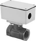
For protection from dirt, washdowns, and corrosion, these switches have an enclosure that meets IP66 and NEMA 4X. They activate or deactivate equipment when the flow rate reaches your set point and have an adjustment screw for altering the set point. All are single pole, double throw (SPDT) and can be installed to turn one circuit from “off” to “on” (normally open) or from “on” to “off” (normally closed).
![]() For technical drawings and 3-D models, click on a part number.
For technical drawings and 3-D models, click on a part number.
| Pipe Size | Thread Type | Gender | Max. Pressure | Temp. Range, °F | Voltage | Current | Conduit Trade Size | End-to-End Lg. | Choose a Set Point, gpm | Each | |
Bronze Body | |||||||||||
|---|---|---|---|---|---|---|---|---|---|---|---|
| 1/4 | NPT | Female | 400 psi @ 70° F | -30° to 212° | 120V AC | 0.4 A @ 120 V AC | 1/2 | 3 1/16" | 0000000 | 0000000 | |
| 1/2 | NPT | Female | 400 psi @ 70° F | -30° to 212° | 120V AC | 0.4 A @ 120 V AC | 1/2 | 3 1/16" | 0000000 | 000000 | |
| 3/4 | NPT | Female | 400 psi @ 70° F | -30° to 212° | 120V AC | 0.4 A @ 120 V AC | 1/2 | 3 1/16" | 0000000 | 000000 | |
| 1 | NPT | Female | 400 psi @ 70° F | -30° to 212° | 120V AC | 0.4 A @ 120 V AC | 1/2 | 3 1/16" | 0000000 | 000000 | |
| 1 1/2 | NPT | Female | 400 psi @ 70° F | -30° to 212° | 120V AC | 0.4 A @ 120 V AC | 1/2 | 3 1/16" | 0000000 | 000000 | |
| 2 | NPT | Female | 400 psi @ 70° F | -30° to 212° | 120V AC | 0.4 A @ 120 V AC | 1/2 | 3 3/16" | 0000000 | 000000 | |
Flow Switches with Indicator for Water

For flow monitoring at a glance, these switches have a plastic window with a rotor indicator that spins when flow is present. They activate or deactivate equipment when the flow rate reaches your set point. All have an adjustment screw for altering the set point to suit your application. Switches are single pole, double throw (SPDT) and can be installed to turn one circuit from "off" to "on" (normally open) or from "on" to "off" (normally closed).
Switches with a polypropylene body are lighter than sights with a metal body.
Switches with a 316 stainless steel body are more corrosion resistant than switches with a brass body.
![]() For technical drawings and 3-D models, click on a part number.
For technical drawings and 3-D models, click on a part number.
| Pipe Size | Thread Type | Gender | Set Point, gpm | Max. Pressure | Temp. Range, °F | Voltage | Current | End-to-End Lg. | Each | |
Polypropylene Plastic Body | ||||||||||
|---|---|---|---|---|---|---|---|---|---|---|
| 1/4 | NPT | Female | 0.1 to 5 | 100 psi @ 70° F | 33° to 180° | 120V AC | 0.3 A @ 120 V AC | 3 1/16" | 0000000 | 0000000 |
| 1/2 | NPT | Female | 1.5 to 20 | 100 psi @ 70° F | 33° to 180° | 120V AC | 0.3 A @ 120 V AC | 3 1/16" | 0000000 | 000000 |
Brass Body | ||||||||||
| 1/4 | NPT | Female | 0.1 to 5 | 200 psi @ 70° F | 33° to 212° | 120V AC | 0.3 A @ 120 V AC | 3" | 0000000 | 000000 |
| 1/2 | NPT | Female | 1.5 to 20 | 200 psi @ 70° F | 33° to 212° | 120V AC | 0.3 A @ 120 V AC | 3" | 0000000 | 000000 |
| 3/4 | NPT | Female | 5 to 30 | 200 psi @ 70° F | 33° to 212° | 120V AC | 0.3 A @ 120 V AC | 3 15/16" | 0000000 | 000000 |
| 1 | NPT | Female | 8 to 60 | 200 psi @ 70° F | 33° to 212° | 120V AC | 0.3 A @ 120 V AC | 3 15/16" | 0000000 | 000000 |
316 Stainless Steel Body | ||||||||||
| 1/2 | NPT | Female | 1.5 to 20 | 200 psi @ 70° F | 33° to 212° | 120V AC | 0.3 A @ 120 V AC | 3" | 0000000 | 000000 |
| 3/4 | NPT | Female | 5 to 30 | 200 psi @ 70° F | 33° to 212° | 120V AC | 0.3 A @ 120 V AC | 3 15/16" | 0000000 | 000000 |
| 1 | NPT | Female | 8 to 60 | 200 psi @ 70° F | 33° to 212° | 120V AC | 0.3 A @ 120 V AC | 3 15/16" | 0000000 | 000000 |
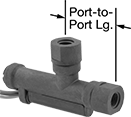
Compact Insertion Flow Switches for Water
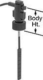
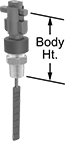
At half the height of standard insertion flow switches, these are often installed in tees or pipe outlets in low-clearance areas. They’re installed in tees or pipe outlets to detect the flow rate of liquid in contact with the sensing paddle. They activate or deactivate equipment when the flow rate reaches your set point. Switches are single pole, double throw (SPDT) and can be installed to turn one circuit from “off” to “on” (normally open). The flow rate varies based on the pipe size and the paddle length.
Maximum flow rate is how much water can temporarily flow through your pipe without damaging the switch.
Switches with a socket-weld connection are for use with unthreaded male pipe. Those with a threaded connection are for use with NPT female pipe.
Switches with a trimmable paddle can be cut to fit a range of pipe sizes. Those with a 301 stainless steel paddle can be used with higher maximum flow rates than switches with a Noryl plastic paddle.
![]() For technical drawings and 3-D models, click on a part number.
For technical drawings and 3-D models, click on a part number.
| Pipe Size | Thread Type | Gender | For Pipe Size | Set Point, gpm | Set Point Adjustment Method | Paddle Material | Max. Flow Rate, gpm | Max. Pressure | Temp. Range, °F | Voltage | Current | Body Ht. | Environmental Rating | Each | |
Noryl Plastic Body | |||||||||||||||
|---|---|---|---|---|---|---|---|---|---|---|---|---|---|---|---|
Socket-Weld Connection | |||||||||||||||
| 1/2 | __ | __ | 1/2 | 0.97 to 1.03 | __ | Noryl Plastic | 7.9 | 160 psi @ 70 ° F | -13° to 212° | 120V AC/ 240V AC | 1 A @ 120 V AC | 2 1/2" | IP65 | 00000000 | 0000000 |
| 3/4 | __ | __ | 3/4 | 1.87 to 1.94 | __ | Noryl Plastic | 21 | 160 psi @ 70 ° F | -13° to 212° | 120V AC/ 240V AC | 1 A @ 120 V AC | 2 1/2" | IP65 | 00000000 | 000000 |
| 3/4 | __ | __ | 1 1/2 to 3 | 8 to 23 | Trimmable Paddles | 301 Stainless Steel | 650 | 160 psi @ 70 ° F | -13° to 212° | 120V AC/ 240V AC | 1 A @ 120 V AC | 2 1/2" | IP65 | 00000000 | 000000 |
| 3/4 | __ | __ | 1 1/2 to 3 | 8 to 23 | Trimmable Paddles | Noryl Plastic | 390 | 160 psi @ 70 ° F | -13° to 212° | 120V AC/ 240V AC | 1 A @ 120 V AC | 2 1/2" | IP65 | 0000000 | 000000 |
| 1 | __ | __ | 1 | 2.4 to 2.7 | __ | Noryl Plastic | 40 | 160 psi @ 70 ° F | -13° to 212° | 120V AC/ 240V AC | 1 A @ 120 V AC | 2 1/2" | IP65 | 00000000 | 000000 |
Threaded Connection | |||||||||||||||
| 1/2 | NPT | Male | 1 1/2 to 8 | 4 to 240 | Trimmable Paddles | 301 Stainless Steel | 650 | 160 psi @ 70 ° F | -13° to 212° | 120V AC/ 240V AC | 1 A @ 120 V AC | 2 1/2" | IP65 | 00000000 | 000000 |
| 1/2 | NPT | Male | 1 1/2 to 8 | 4 to 240 | Trimmable Paddles | Noryl Plastic | 1,100 | 160 psi @ 70 ° F | -13° to 212° | 120V AC/ 240V AC | 1 A @ 120 V AC | 2 1/2" | IP65 | 0000000 | 000000 |
Insertion Flow Switches for Water
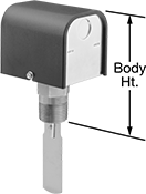
Install these switches in tees or pipe outlets to detect the flow rate of liquid in contact with the sensing paddle. They activate or deactivate equipment when the flow rate reaches your set point. Switches are single pole, double throw (SPDT) and can be installed to turn one circuit from “off” to “on” (normally open) or from “on” to “off” (normally closed). They come with four sensing paddles that can be trimmed to fit a range of pipe sizes. The flow rate varies based on the pipe size and paddle used.
Switch with a 316 stainless steel body is more corrosion resistant than switches with a brass body.
Switch with an enclosure that meets NEMA 4X provides protection from dirt, washdowns, and corrosive liquids.
![]() For technical drawings and 3-D models, click on a part number.
For technical drawings and 3-D models, click on a part number.
| Pipe Size | Thread Type | Gender | For Pipe Size | Set Point, gpm | Max. Pressure | Temp. Range, °F | Voltage | Current | Body Ht. | Environmental Rating | Specifications Met | Each | |
Brass Body | |||||||||||||
|---|---|---|---|---|---|---|---|---|---|---|---|---|---|
| 1 | NPT | Male | 1 to 6 | 5 to 245 | 160 psi @ 70° F | 33° to 225° | 120V AC/ 240V AC | 7.4 A @ 120 V AC | 5" | NEMA 4X | C-UL Listed, UL Recognized Component | 000000 | 0000000 |
| 1 | NPT | Male | 1 to 6 | 6 to 166 | 160 psi @ 70° F | 33° to 300° | 120V AC/ 240V AC | 7.4 A @ 120 V AC | 5" | __ | C-UL Listed, UL Listed | 000000 | 000000 |
316 Stainless Steel Body | |||||||||||||
| 1 | NPT | Male | 1 to 6 | 6 to 166 | 160 psi @ 70° F | 33° to 300° | 120V AC/ 240V AC | 7.4 A @ 120 V AC | 5" | __ | C-UL Listed, UL Listed | 000000 | 000000 |
Hazardous Location Insertion Flow Switches for Water, Oil, Air, and Inert Gas
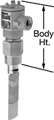
For installation in environments with flammable gases and combustible dust, these flow switches are UL listed for hazardous locations. They meet NEC Class I, Divisions 1 and 2, Groups C and D; and NEC Class II, Divisions 1 and 2, Groups E, F, and G. They’re installed in tees or pipe outlets to detect the flow rate of liquid in contact with the sensing paddle. Switches activate or deactivate equipment when the flow rate reaches your set point. All come with five sensing paddles that can be trimmed to fit a range of pipe sizes. The flow rate varies based on the pipe size and paddle used.
SPDT switches control one circuit. They can be installed to turn the circuit from “off” to “on” (normally open) or from “on” to “off” (normally closed).
DPDT switches control two circuits. They can be installed to turn both circuits from “off” to “on” (normally open) or from “on” to “off” (normally closed).
Switches with a 316 stainless steel body are more corrosion resistant than switches with a brass body.
![]() For technical drawings and 3-D models, click on a part number.
For technical drawings and 3-D models, click on a part number.
Set Point | Conduit | ||||||||||||||
|---|---|---|---|---|---|---|---|---|---|---|---|---|---|---|---|
| Pipe Size | Thread Type | Gender | For Pipe Size | For Water and Oil, gpm | For Air and Inert Gas, scfm | Max. Pressure | Temp. Range, °F | Voltage | Current | Trade Size | Thread Type | Gender | Body Ht. | Each | |
SPDT | |||||||||||||||
Brass Body | |||||||||||||||
| 1 1/2 | NPT | Male | 1 1/2 to 20 | 3 to 2,400 | 17 to 10,000 | 1000 psi @ 70° F | -4° to 275° | 120V AC 240V AC | 10 A @ 120 V AC | 3/4 | NPT | Female | 8" | 00000000 | 0000000 |
316 Stainless Steel Body | |||||||||||||||
| 1 1/2 | NPT | Male | 1 1/2 to 20 | 3 to 2,400 | 17 to 10,000 | 2000 psi @ 70° F | -4° to 275° | 120V AC 240V AC | 10 A @ 120 V AC | 3/4 | NPT | Female | 8" | 00000000 | 000000 |
DPDT | |||||||||||||||
Brass Body | |||||||||||||||
| 1 1/2 | NPT | Male | 1 1/2 to 20 | 3 to 2,400 | 17 to 10,000 | 1000 psi @ 70° F | -4° to 275° | 120V AC 240V AC | 10 A @ 120 V AC | 3/4 | NPT | Female | 8" | 00000000 | 000000 |
316 Stainless Steel Body | |||||||||||||||
| 1 1/2 | NPT | Male | 1 1/2 to 20 | 3 to 2,400 | 17 to 10,000 | 2000 psi @ 70° F | -4° to 275° | 120V AC 240V AC | 10 A @ 120 V AC | 3/4 | NPT | Female | 8" | 00000000 | 000000 |
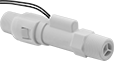
Flow Transmitters for Water

Send flow-rate readings to data recorders, loggers, and displays.
Transmitters with a 316 stainless steel body are more corrosion resistant than transmitters with a brass or polypropylene body.
![]() For technical drawings and 3-D models, click on a part number.
For technical drawings and 3-D models, click on a part number.
Output | |||||||||||||
|---|---|---|---|---|---|---|---|---|---|---|---|---|---|
| Pipe Connections | End-to-End Lg. | Flow Range, gpm | Accuracy | Max. Pressure | Temp. Range, °F | Seal Material | Mounting Orientation | Signal Connection | Signal, mA | Current | Wire Lead Lg. | Each | |
Polypropylene Plastic Body | |||||||||||||
Gallons per Minute | |||||||||||||
| 1/4 NPT Female | 3 1/16" | 0.1 to 5 | ±7% | 100 psi @ 70° F | 33° to 180° | Fluoroelastomer Rubber | Horizontal, Vertical | Wire Leads | 70 | 0.008 A @ 24 V DC | 24" | 0000000 | 0000000 |
| 1/2 NPT Female | 3 1/16" | 1.5 to 20 | ±15% | 100 psi @ 70° F | 33° to 180° | Fluoroelastomer Rubber | Horizontal, Vertical | Wire Leads | 70 | 0.008 A @ 24 V DC | 24" | 0000000 | 000000 |
Brass Body | |||||||||||||
Gallons per Minute | |||||||||||||
| 1/4 NPT Female | 3" | 0.1 to 5 | ±7% | 200 psi @ 70° F | 33° to 212° | Fluoroelastomer Rubber | Horizontal, Vertical | Wire Leads | 70 | 0.008 A @ 24 V DC | 24" | 0000000 | 000000 |
| 1/2 NPT Female | 3" | 1.5 to 20 | ±15% | 200 psi @ 70° F | 33° to 212° | Fluoroelastomer Rubber | Horizontal, Vertical | Wire Leads | 70 | 0.008 A @ 24 V DC | 24" | 0000000 | 000000 |
| 1 NPT Female | 3 15/16" | 8 to 60 | ±15% | 200 psi @ 70° F | 33° to 212° | Fluoroelastomer Rubber | Horizontal, Vertical | Wire Leads | 70 | 0.008 A @ 24 V DC | 24" | 0000000 | 000000 |
316 Stainless Steel Body | |||||||||||||
Gallons per Minute | |||||||||||||
| 1/2 NPT Female | 3" | 1.5 to 20 | ±15% | 200 psi @ 70° F | 33° to 212° | Fluoroelastomer Rubber | Horizontal, Vertical | Wire Leads | 70 | 0.008 A @ 24 V DC | 24" | 0000000 | 000000 |
| 3/4 NPT Female | 3 15/16" | 5 to 30 | ±15% | 200 psi @ 70° F | 33° to 212° | Fluoroelastomer Rubber | Horizontal, Vertical | Wire Leads | 70 | 0.008 A @ 24 V DC | 24" | 0000000 | 000000 |
| 1 NPT Female | 3 15/16" | 8 to 60 | ±15% | 200 psi @ 70° F | 33° to 212° | Fluoroelastomer Rubber | Horizontal, Vertical | Wire Leads | 70 | 0.008 A @ 24 V DC | 24" | 0000000 | 000000 |
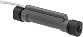
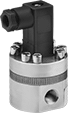
Compact Flow Transmitters for Water
Use these transmitters in areas with limited clearance to send flow-rate readings to data recorders, loggers, and displays. They have a 316 stainless steel body for corrosion resistance in harsh environments.
Optional display meter accepts flowmeter output signals and registers flow rate and total. The display can be manually reset.
![]() For technical drawings and 3-D models, click on a part number.
For technical drawings and 3-D models, click on a part number.
Output | |||||||||||||
|---|---|---|---|---|---|---|---|---|---|---|---|---|---|
| Pipe Connections | Overall Ht. | Dia. | Flow Range, ml/min. | Accuracy | Max. Pressure | Temp. Range, °F | Seal Material | Mounting Orientation | Signal Connection | Signal | Voltage | Each | |
316 Stainless Steel Body | |||||||||||||
Milliliters per Minute | |||||||||||||
| 1/8 NPT Female | 2 7/8" | 1 1/2" | 3 to 300 | ±0.5% | 1450 psi @ 70° F | -22° to 176° | Viton® Fluoroelastomer | Horizontal, Vertical | Wire Leads | 3V DC to 25V DC | 4V DC 26V DC | 0000000 | 000000000 |
| 1/8 NPT Female | 2 7/8" | 1 15/16" | 10 to 1,000 | ±0.5% | 1450 psi @ 70° F | -22° to 176° | Viton® Fluoroelastomer | Horizontal, Vertical | Wire Leads | 3V DC to 25V DC | 4V DC 26V DC | 0000000 | 00000000 |
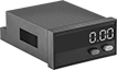
Overall | ||||||||
|---|---|---|---|---|---|---|---|---|
| Ht. | Wd. | Dp. | Wire Connection Type | Reset Type | Environmental Rating | Specifications Met | Each | |
| 0.945" | 1.89" | 2.729" | Screw Terminals | Button | IP65 | UL Recognized Component, C-UL Recognized Component, CE Marked | 0000000 | 0000000 |
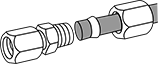
Flow Transmitters for Air
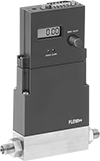
Calibrated for compressed air, these transmitters send flow-rate readings to data recorders, loggers, and displays. They have compression tube connections that bite down on hard metal and plastic tubing for a secure seal. The digital display shows the flow rate, so these transmitters can also be used as flowmeters. Fittings are 316 stainless steel for corrosion resistance in harsh environments.
![]() For technical drawings and 3-D models, click on a part number.
For technical drawings and 3-D models, click on a part number.
Output | |||||||||||||
|---|---|---|---|---|---|---|---|---|---|---|---|---|---|
| Tube Connections | End-to-End Lg. | Flow Range | Accuracy | Max. Pressure | Temp. Range, °F | Seal Material | Mounting Orientation | Signal Connection | Signal | Voltage | Plug Type | Each | |
ABS Plastic Body with 316 Stainless Steel | |||||||||||||
Cubic Centimeters per Minute | |||||||||||||
| Male Compression for 1/8" Tube OD | 4 7/8" | 1.08 to 54 cc/min. | ±3% | 150 psi @ 70° F | 32° to 122° | Elastomer Rubber | Horizontal | RS-232 Port | 4 to 20 mA | 120V AC 240V AC | Two Prong | 0000000 | 000000000 |
| Male Compression for 1/8" Tube OD | 4 7/8" | 4 to 200 cc/min. | ±3% | 150 psi @ 70° F | 32° to 122° | Elastomer Rubber | Horizontal | RS-232 Port | 4 to 20 mA | 120V AC 240V AC | Two Prong | 0000000 | 00000000 |
| Male Compression for 1/8" Tube OD | 4 7/8" | 10 to 500 cc/min. | ±3% | 150 psi @ 70° F | 32° to 122° | Elastomer Rubber | Horizontal | RS-232 Port | 4 to 20 mA | 120V AC 240V AC | Two Prong | 0000000 | 00000000 |
Liters per Minute | |||||||||||||
| Male Compression for 1/8" Tube OD | 4 7/8" | 0.02 to 1 lpm | ±3% | 150 psi @ 70° F | 32° to 122° | Elastomer Rubber | Horizontal | RS-232 Port | 4 to 20 mA | 120V AC 240V AC | Two Prong | 0000000 | 00000000 |
| Male Compression for 1/8" Tube OD | 4 7/8" | 0.1 to 5 lpm | ±3% | 150 psi @ 70° F | 32° to 122° | Elastomer Rubber | Horizontal | RS-232 Port | 4 to 20 mA | 120V AC 240V AC | Two Prong | 0000000 | 00000000 |
Airflow-Actuated HVAC Switches
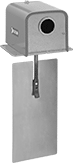
Use this switch to sense changes in airflow velocity in duct. The paddle extends into the duct and actuates the switch when airflow reaches the setpoint. Switch is rated NEMA 3R for protection from dirt, falling liquids, and light splashing.
Paddle | ||||||||||||||
|---|---|---|---|---|---|---|---|---|---|---|---|---|---|---|
| Setpoint, fpm | Temperature Range, °F | Current | Electrical Connection Type | Switch Type | For Conduit Trade Size | Knockout Dia. | Material | Ht. | Wd. | For Use Outdoors | Environmental Rating | Specifications Met | Each | |
Paddle Sensor | ||||||||||||||
| 350-500 | 32° to 104° | 10 A @ 240 V AC 16 A @ 120 V AC | Screw Terminal | SPDT | 1/2 | 7/8" | Stainless Steel | 6 7/8" | 3 1/8" | Yes | IP43, NEMA 3R | UL Listed, C-UL Listed, CE Marked | 0000000 | 0000000 |
Air-Pressure-Actuated HVAC Switches
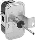
Often used to detect clogged air filters and iced air conditioner coils, these switches sense small changes in pressure between two points in your duct.
| Setpoint, in. of H2O | Accuracy, in. of H2O | Temperature Range, °F | Current | Electrical Connection Type | Switch Type | Max. Pressure, psi | Low Pressure Side Connection | High Pressure Side Inside Connection | High Pressure Side Outside Connection | Each | |
Diaphragm Sensor | |||||||||||
|---|---|---|---|---|---|---|---|---|---|---|---|
| 0.05-5 | 0.025 | -40° to 165° | 2.9 A @ 240 V AC 5.8 A @ 120 V AC | Hardwire | SPDT | 1 | 1/8 NPT Female | 1/8 NPT Female | 1/2 NPSM | 000000 | 0000000 |
| 0.05-5 | 0.04 | -40° to 165° | 4.9 A @ 240 V AC 9.8 A @ 120 V AC | Hardwire | SPDT | 1 | 1/8 NPT Female | 1/8 NPT Female | 1/2 NPSM | 000000 | 000000 |