


Find a gauge with the right connection material and dial type—many with traceable calibration certificates.
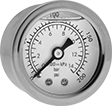
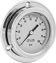
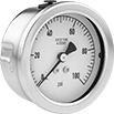
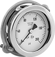
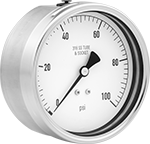
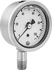
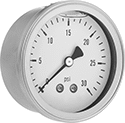
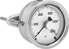
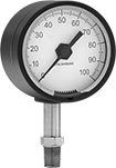
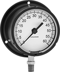
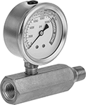
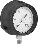
Vibration-Resistant Pressure Gauges
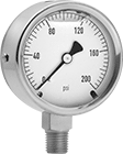 |  |  |
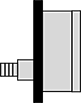
Bottom Connection | Center-Back Connection | Lower-Back Connection |
 | |
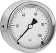
Bottom Connection | Center-Back Connection |
 | |
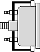
Lower-Back Connection |
Temp. Range, ° F | Bottom Connection | Center-Back Connection | Lower-Back Connection | ||||||||||||
|---|---|---|---|---|---|---|---|---|---|---|---|---|---|---|---|
Dial Dia. | Pipe Size | Environment | Process | Liquid Type | For Use With | Accuracy | Pressure Range | Each | Each | Each | |||||
Upright Mount | |||||||||||||||
NPT Male with Calibration Certificate Traceable to NIST | |||||||||||||||
| 2 1/2" | 1/4 | 0 to 140 | 0 to 140 | Glycerin | Air Carbon Dioxide Ethanol Hydraulic Fluid Natural Gas Water | ±1.5% Full Scale (Not Rated) | 0 to 10,000 psi | 3481K11 | 0000000 | 3481K21 | 0000000 | ——— | 0 | ||
| 4" | 1/4 | 0 to 140 | 0 to 140 | Glycerin | Air Carbon Dioxide Ethanol Hydraulic Fluid Natural Gas Water | ±1% Full Scale (Grade 1A) | 0 to 10,000 psi | 3481K12 | 000000 | ——— | 0 | 3481K22 | 0000000 | ||
 |  | | |
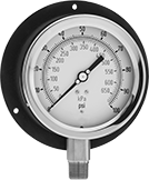
Bottom Connection | Center-Back Connection | Bottom Connection | Center-Back Connection |
Temp. Range, ° F | Bottom Connection | Center-Back Connection | |||||||||||
|---|---|---|---|---|---|---|---|---|---|---|---|---|---|
Dial Dia. | Pipe Size | Environment | Process | Liquid Type | For Use With | Accuracy | Pressure Range | Each | Each | ||||
Upright Mount | |||||||||||||
NPT Male | |||||||||||||
| 2 1/2" | 1/4 | 0 to 140 | 0 to 140 | Glycerin | Air Carbon Dioxide Hydraulic Fluid Natural Gas Water | ±1.5% Full Scale (Not Rated) | 0 to 10,000 psi/0 to 680 bar | 1798T11 | 000000 | 1798T21 | 000000 | ||
| |  |
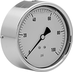
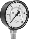
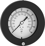
Bottom Connection | Center-Back Connection | Lower-Back Connection |
| |
Bottom Connection | Center-Back Connection |
| |
Lower-Back Connection |
Temp. Range, ° F | Bottom Connection | Center-Back Connection | Lower-Back Connection | ||||||||||||
|---|---|---|---|---|---|---|---|---|---|---|---|---|---|---|---|
Dial Dia. | Pipe Size | Environment | Process | Liquid Type | For Use With | Accuracy | Pressure Range | Each | Each | Each | |||||
Upright Mount | |||||||||||||||
NPT Male | |||||||||||||||
| 2 1/2" | 1/4 | 0 to 140 | 0 to 140 | Glycerin | Air Hydraulic Fluid Water | ±1% Midscale (Grade A) | 0 to 10,000 psi/0 to 68,000 kPa | 4053K15 | 000000 | 4053K18 | 000000 | ——— | 0 | ||
| 4" | 1/4 | 0 to 140 | 0 to 140 | Glycerin | Air Hydraulic Fluid Water | ±1% Full Scale (Grade 1A) | 0 to 10,000 psi/0 to 68,000 kPa | 4053K16 | 00000 | ——— | 0 | 4053K17 | 000000 | ||
NPT Male with Calibration Certificate Traceable to NIST | |||||||||||||||
| 2 1/2" | 1/4 | 0 to 140 | 0 to 140 | Glycerin | Air Hydraulic Fluid Water | ±1% Midscale (Grade A) | 0 to 10,000 psi/0 to 68,000 kPa | 4053K23 | 000000 | 4053K25 | 000000 | ——— | 0 | ||
| 4" | 1/4 | 0 to 140 | 0 to 140 | Glycerin | Air Hydraulic Fluid Water | ±1% Full Scale (Grade 1A) | 0 to 10,000 psi/0 to 68,000 kPa | 4053K24 | 000000 | ——— | 0 | 4053K26 | 000000 | ||
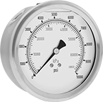
High-Accuracy Vibration- and Corrosion-Resistant Pressure Gauges
 |  |  |
Bottom Connection | Lower-Back Connection | Lower-Back Connection (Flange Mount) |
|  | |
Bottom Connection | Lower-Back Connection | Lower-Back Connection (Flange Mount) |
Bottom Connection | Lower-Back Connection | Lower-Back Connection (Flange Mount) | |||||||||||||||||||
|---|---|---|---|---|---|---|---|---|---|---|---|---|---|---|---|---|---|---|---|---|---|
Temp. Range, ° F | Bolt | Flange | |||||||||||||||||||
Dial Dia. | Pipe Size | Environment | Process | Liquid Type | For Use With | Accuracy | Pressure Range | Each | Each | Mounting Fasteners Included | Circle Dia. | Hole Dia. | No. of Holes | Location | OD | Each | |||||
Upright Mount | |||||||||||||||||||||
NPT Male | |||||||||||||||||||||
| 2 1/2" | 1/4 | 0 to 155 | 0 to 140 | Glycerin | Air Hydraulic Fluid Water | ±1% Full Scale (Grade 1A) | 0 to 10,000 psi | 4088K3 | 0000000 | 4088K6 | 0000000 | No | 2 15/16" | 9/64" | 3 | Front | 3 3/8" | 4088K7 | 0000000 | ||
| 4" | 1/4 | 0 to 140 | 0 to 210 | Glycerin | Air Hydraulic Fluid Water | ±1% Full Scale (Grade 1A) | 0 to 10,000 psi | 4088K511 | 000000 | 4088K821 | 000000 | No | 4 9/16" | 3/16" | 3 | Front | 5 3/16" | 4088K92 | 000000 | ||
| 6" | 1/4 | 0 to 155 | 0 to 140 | Glycerin | Air Hydraulic Fluid Water | ±0.5% Full Scale (Grade 2A) | 0 to 10,000 psi | 4088K1 | 000000 | 4088K2 | 000000 | No | 7" | 15/64" | 3 | Front | 7 3/4" | 4088K4 | 000000 | ||
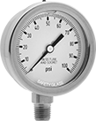
High-Accuracy Corrosion-Resistant Pressure Gauges
 |  |  |  |
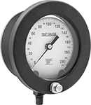
Bottom Connection | Center-Back Connection | Center-Back Connection (Panel Mount) | Lower-Back Connection |
|  | | |
Bottom Connection | Center-Back Connection | Center-Back Connection (Panel Mount) | Lower-Back Connection |
Temp. Range, ° F | Bottom Connection | Center-Back Connection | Center-Back Connection (Panel Mount) | Lower-Back Connection | |||||||||||||
|---|---|---|---|---|---|---|---|---|---|---|---|---|---|---|---|---|---|
Dial Dia. | Pipe Size | Environment | Process | For Use With | Accuracy | Pressure Range | Each | Each | For Panel Cutout Dia. | Each | Each | ||||||
Upright Mount | |||||||||||||||||
NPT Male | |||||||||||||||||
| 2 1/2" | 1/4 | -40 to 140 | -40 to 390 | Air Diesel Fuel Gasoline Hydraulic Fluid Natural Gas Water | ±1.5% Full Scale (Not Rated) | 0 to 10,000 psi | 3852K125 | 0000000 | 3852K225 | 0000000 | 2 1/2" | 3852K425 | 0000000 | ——— | 0 | ||
| 4" | 1/2 | -40 to 140 | -40 to 390 | Air Diesel Fuel Gasoline Hydraulic Fluid Natural Gas Water | ±1% Full Scale (Grade 1A) | 0 to 10,000 psi | 3852K875 | 000000 | ——— | 0 | — | ——— | 0 | 3852K925 | 0000000 | ||
NPT Male with Calibration Certificate Traceable to NIST | |||||||||||||||||
| 2 1/2" | 1/4 | -40 to 140 | -40 to 390 | Air Diesel Fuel Gasoline Hydraulic Fluid Natural Gas Water | ±1.5% Full Scale (Not Rated) | 0 to 10,000 psi | 3906K11 | 000000 | 3906K31 | 000000 | — | ——— | 0 | ——— | 0 | ||
| 4" | 1/2 | -40 to 140 | -40 to 390 | Air Diesel Fuel Gasoline Hydraulic Fluid Natural Gas Water | ±1% Full Scale (Grade 1A) | 0 to 10,000 psi | 3906K21 | 000000 | ——— | 0 | — | ——— | 0 | 3906K41 | 000000 | ||
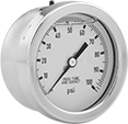
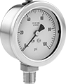
Vibration- and Corrosion-Resistant Pressure Gauges
 |  |  |
Bottom Connection | Center-Back Connection | Lower-Back Connection |
| | |
Bottom Connection | Center-Back Connection | Lower-Back Connection |
Temp. Range, ° F | Bottom Connection | Center-Back Connection | Lower-Back Connection | |||||||||||||
|---|---|---|---|---|---|---|---|---|---|---|---|---|---|---|---|---|
Dial Dia. | Pipe Size | Environment | Process | Mounting Position | Liquid Type | For Use With | Accuracy | Pressure Range | Each | Each | Each | |||||
NPT Male with Calibration Certificate Traceable to NIST | ||||||||||||||||
| 2 1/2" | 1/4 | 0 to 140 | 0 to 212 | Upright | Glycerin | Air Diesel Fuel Gasoline Hydraulic Fluid Natural Gas Water | ±1.5% Full Scale (Not Rated) | 0 to 10,000 psi | 3902K11 | 0000000 | 3902K41 | 0000000 | ——— | 0 | ||
| 4" | 1/2 | 0 to 140 | 0 to 212 | Upright | Glycerin | Air Diesel Fuel Gasoline Hydraulic Fluid Natural Gas Water | ±1% Full Scale (Grade 1A) | 0 to 10,000 psi | 3902K21 | 000000 | ——— | 0 | 3902K51 | 0000000 | ||
Maximum-Indicating Vibration-Resistant Pressure Gauges
 |  |  | | | |
Bottom Connection | Center-Back Connection | Center-Back Connection (Panel Mount) | Bottom Connection | Center-Back Connection | Center-Back Connection (Panel Mount) |
Temp. Range, ° F | Bottom Connection | Center-Back Connection | Center-Back Connection (Panel Mount) | ||||||||||||||
|---|---|---|---|---|---|---|---|---|---|---|---|---|---|---|---|---|---|
Dial Dia. | Pipe Size | Environment | Process | Liquid Type | Features | For Use With | Accuracy | Pressure Range | Each | Each | For Panel Cutout Dia. | Each | |||||
Upright Mount | |||||||||||||||||
NPT Male | |||||||||||||||||
| 2 1/2" | 1/4 | 0 to 140 | 0 to 140 | Glycerin | Red Pressure Spike Needle | Air Carbon Dioxide Ethanol Hydraulic Fluid Natural Gas Water | ±1.5% Full Scale (Not Rated) | 0 to 10,000 psi | 3842K11 | 0000000 | 3842K21 | 0000000 | 2 1/2" | 3842K81 | 0000000 | ||
NPT Male with Calibration Certificate Traceable to NIST | |||||||||||||||||
| 2 1/2" | 1/4 | 0 to 140 | 0 to 140 | Glycerin | Red Pressure Spike Needle | Air Carbon Dioxide Ethanol Hydraulic Fluid Natural Gas Water | ±1.5% Full Scale (Not Rated) | 0 to 10,000 psi | 3842K31 | 000000 | 3842K41 | 000000 | 2 1/2" | 3842K83 | 000000 | ||
Extreme-Temperature Pressure Gauges
 |  | ||
Bottom Connection | Bottom Connection (Flange Mount) | Bottom Connection | Bottom Connection (Flange Mount) |
Bottom Connection | Bottom Connection (Flange Mount) | ||||||||||||||||||
|---|---|---|---|---|---|---|---|---|---|---|---|---|---|---|---|---|---|---|---|
Environment Temp. Range, ° F | Process Temp. Range, ° F | Flange | Bolt | ||||||||||||||||
Dial Dia. | Pipe Size | Min. | Max. | Min. | Max. | For Use With | Pressure Range | Each | Location | OD | Mounting Fasteners Included | Circle Dia. | Hole Dia. | No. of Holes | Each | ||||
Upright Mount | |||||||||||||||||||
NPT Male | |||||||||||||||||||
| 2 1/2" | 1/4 | -65 | 400 | -65 | 600 | Air Diesel Fuel Gasoline Hydraulic Fluid Natural Gas Water | 0 to 10,000 psi | 9891T23 | 0000000 | — | — | — | — | — | — | ——— | 0 | ||
| 3 1/2" | 1/4 | -65 | 400 | -65 | 600 | Air Diesel Fuel Gasoline Hydraulic Fluid Natural Gas Water | 0 to 10,000 psi | ——— | 0 | Back | 4 3/4" | No | 4 1/4" | 7/32" | 3 | 9891T24 | 0000000 | ||
| |
Bottom Connection (Flange Mount) | Bottom Connection (Flange Mount) |
Bottom Connection (Flange Mount) | |||||||||||||||
|---|---|---|---|---|---|---|---|---|---|---|---|---|---|---|---|
Environment Temp. Range, ° F | Process Temp. Range, ° F | Mounting | |||||||||||||
Dial Dia. | Pipe Size | Min. | Max. | Min. | Max. | Case Color | For Use With | Pressure Range | Fasteners Included | Hole Dia. | No. of Holes | Each | |||
Upright Mount | |||||||||||||||
NPT Male | |||||||||||||||
| 4 1/2" | 1/2 | -65 | 400 | -65 | 600 | Yellow | Air Diesel Fuel Gasoline Hydraulic Fluid Natural Gas Water | 0 to 10,000 psi | No | 7/32" | 3 | 9891T25 | 0000000 | ||
Pressure Gauges for Hydraulic Jacks
Pressure Test Gauges
 | |
Bottom Connection/Flange Mount | Bottom Connection |
Pressure, psi | Mounting Holes | Bottom Connection/Flange Mount | |||||||||||||
|---|---|---|---|---|---|---|---|---|---|---|---|---|---|---|---|
Range | Graduations | Numeric Increments | Accuracy | Environment Temp. Range, ° F | Process Temp. Range, ° F | Case Color | Mounting Fasteners Included | Dia. | No. of | For Use With | Features | Each | |||
NPT Male | |||||||||||||||
4 1/2" Diameter Dial—1/2 Pipe Size | |||||||||||||||
| 0 to 10,000 | 100 | 1,000 | ±0.5% Full Scale (Grade 2A) | 0 to 150 | 0 to 210 | Black | No | 1/4" | 3 | Air, Diesel Fuel, Gasoline, Hydraulic Fluid, Natural Gas, Water | Glow-in-the-Dark Dial, Safety Case | 4063K156 | 0000000 | ||
| 0 to 10,000 | 100 | 1,000 | ±0.5% Full Scale (Grade 2A) | 0 to 150 | 0 to 210 | Black | No | 1/4" | 3 | Air, Diesel Fuel, Gasoline, Hydraulic Fluid, Natural Gas, Water | Safety Case | 4065K726 | 000000 | ||
NPT Male—Calibration Certificate Traceable to NIST | |||||||||||||||
4 1/2" Diameter Dial—1/2 Pipe Size | |||||||||||||||
| 0 to 10,000 | 100 | 1,000 | ±0.5% Full Scale (Grade 2A) | 0 to 150 | 0 to 210 | Black | No | 1/4" | 3 | Air, Diesel Fuel, Gasoline, Hydraulic Fluid, Natural Gas, Water | Glow-in-the-Dark Dial, Safety Case | 4063K326 | 000000 | ||
| 0 to 10,000 | 100 | 1,000 | ±0.5% Full Scale (Grade 2A) | 0 to 150 | 0 to 210 | Black | No | 1/4" | 3 | Air, Diesel Fuel, Gasoline, Hydraulic Fluid, Natural Gas, Water | Safety Case | 4065K206 | 000000 | ||
 | |
Bottom Connection/Flange Mount | Bottom Connection |
Pressure | Mounting Holes | Bottom Connection/Flange Mount | |||||||||||||
|---|---|---|---|---|---|---|---|---|---|---|---|---|---|---|---|
Range | Graduations | Numeric Increments | Accuracy | Environment Temp. Range, ° F | Process Temp. Range, ° F | Case Color | Mounting Fasteners Included | Dia. | No. of | For Use With | Features | Each | |||
NPT Male | |||||||||||||||
4 1/2" Diameter Dial—1/2 Pipe Size | |||||||||||||||
| 0 psi to 10,000 psi 0 kPa to 68,500 kPa | 100 psi, 500 kPa | 1,000 psi; 5,000 kPa | ±0.5% Full Scale (Grade 2A) | 0 to 150 | 0 to 210 | Black | No | 1/4" | 3 | Air, Diesel Fuel, Gasoline, Hydraulic Fluid, Natural Gas, Water | Safety Case | 4065K46 | 0000000 | ||
NPT Male—Calibration Certificate Traceable to NIST | |||||||||||||||
4 1/2" Diameter Dial—1/2 Pipe Size | |||||||||||||||
| 0 psi to 10,000 psi 0 kPa to 68,500 kPa | 100 psi, 500 kPa | 1,000 psi; 5,000 kPa | ±0.5% Full Scale (Grade 2A) | 0 to 150 | 0 to 210 | Black | No | 1/4" | 3 | Air, Diesel Fuel, Gasoline, Hydraulic Fluid, Natural Gas, Water | Safety Case | 4065K227 | 000000 | ||
|  |
Bottom Connection/Flange Mount | Lower-Back Connection/Flange Mount |
Bottom Connection |
 |
Lower-Back Connection |
Bottom Connection/Flange Mount | Lower-Back Connection/Flange Mount | |||||||||||||||||||
|---|---|---|---|---|---|---|---|---|---|---|---|---|---|---|---|---|---|---|---|---|
Pressure | Bolt | Flange | Flange | |||||||||||||||||
Range | Graduations | Numeric Increments | Accuracy | Environment Temp. Range, ° F | Process Temp. Range, ° F | Mounting Fasteners Included | For Use With | Circle Dia. | No. of Holes | Hole Dia. | Location | OD | Each | Location | OD | Each | ||||
NPT Male | ||||||||||||||||||||
4 1/2" Diameter Dial—1/2 Pipe Size | ||||||||||||||||||||
| 0 psi to 10,000 psi 0 kPa to 68,500 kPa | 100 psi, 500 kPa | 1,000 psi; 10,000 kPa | ±0.5% Full Scale (Grade 2A) | -40 to 150 | -40 to 225 | No | Air, Hydraulic Fluid, Natural Gas, Water | 5 3/8" | 3 | 13/64" | Back | 5 7/8" | 4008K27 | 0000000 | Front | 6" | 4008K76 | 0000000 | ||
NPT Male—Calibration Certificate Traceable to NIST | ||||||||||||||||||||
4 1/2" Diameter Dial—1/2 Pipe Size | ||||||||||||||||||||
| 0 psi to 10,000 psi 0 kPa to 68,500 kPa | 100 psi, 500 kPa | 1,000 psi; 10,000 kPa | ±0.5% Full Scale (Grade 2A) | -40 to 150 | -40 to 225 | No | Air, Hydraulic Fluid, Natural Gas, Water | 5 3/8" | 3 | 13/64" | Back | 5 7/8" | 4008K116 | 000000 | Front | 6" | 4008K227 | 000000 | ||
High-Accuracy Pressure Test Gauges
 | |
Bottom Connection/Flange Mount | |||||||||||||||||
|---|---|---|---|---|---|---|---|---|---|---|---|---|---|---|---|---|---|
Pressure, psi | Bolt | Flange | |||||||||||||||
Range | Graduations | Numeric Increments | Accuracy | Environment Temp. Range, ° F | Process Temp. Range, ° F | Case Color | Mounting Fasteners Included | For Use With | Circle Dia. | Hole Thread Size | No. of Holes | Location | OD | Each | |||
NPT Male | |||||||||||||||||
4 1/2" Diameter Dial—1/2 Pipe Size | |||||||||||||||||
| 0 to 10,000 | 100 | 500 | ±0.25% Full Scale (Grade 3A) | -20 to 200 | -20 to 250 | Black | No | Air, Ethyl Alcohol, Hydraulic Fluid, Natural Gas, Nitrogen, Water | 5 3/8" | 10-24 | 3 | Front | 6 3/32" | 4009K532 | 0000000 | ||
6" Diameter Dial—1/2 Pipe Size | |||||||||||||||||
| 0 to 10,000 | 100 | 500 | ±0.25% Full Scale (Grade 3A) | -20 to 200 | -20 to 250 | Black | No | Air, Ethyl Alcohol, Hydraulic Fluid, Natural Gas, Nitrogen, Water | 7" | 1/4"-20 | 3 | Front | 7 9/16" | 4009K562 | 000000 | ||
NPT Male—Calibration Certificate Traceable to NIST | |||||||||||||||||
4 1/2" Diameter Dial—1/2 Pipe Size | |||||||||||||||||
| 0 to 10,000 | 50 | 500 | ±0.25% Full Scale (Grade 3A) | -20 to 200 | -20 to 250 | Black | No | Air, Ethyl Alcohol, Hydraulic Fluid, Natural Gas, Nitrogen, Water | 5 3/8" | 10-24 | 3 | Front | 6 3/32" | 4009K636 | 000000 | ||
6" Diameter Dial—1/2 Pipe Size | |||||||||||||||||
| 0 to 10,000 | 20 | 500 | ±0.25% Full Scale (Grade 3A) | -20 to 200 | -20 to 250 | Black | No | Air, Ethyl Alcohol, Hydraulic Fluid, Natural Gas, Nitrogen, Water | 7" | 1/4"-20 | 3 | Front | 7 9/16" | 4009K736 | 000000 | ||
Corrosion-Resistant Pressure Test Gauges
 | |
Bottom Connection | Bottom Connection |
Pressure, psi | Bottom Connection | |||||||||
|---|---|---|---|---|---|---|---|---|---|---|
Range | Graduations | Numeric Increments | Accuracy | Environment Temp. Range, ° F | Process Temp. Range, ° F | For Use With | Each | |||
NPT Male—Calibration Certificate Traceable to NIST | ||||||||||
4 1/2" Diameter Dial—1/2 Pipe Size | ||||||||||
| 0 to 10,000 | 100 | 1,000 | ±0.5% Full Scale (Grade 2A) | -40 to 150 | -40 to 225 | Air, Hydraulic Fluid, Natural Gas, Water | 3702K558 | 0000000 | ||
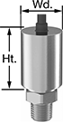
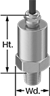
Pressure Transmitters
 |
Pressure Range, psi | Max. Continuous Pressure, psi | Max. Short-Term Pressure, psi | Input Voltage, V DC | Ht. | Wd. | Enclosure Rating | Certification | For Use With | Accuracy | Housing Material | Connection Material | Temp. Range, ° F | Each | |||
|---|---|---|---|---|---|---|---|---|---|---|---|---|---|---|---|---|
1/4 NPT Male Pipe Connection | ||||||||||||||||
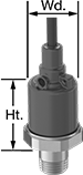
| 0 to 10,000 | 10,000 | 12,000 | 9 to 36 | 1 15/16" | 15/16" | IP67, NEMA 4X | UL Recognized Component, C-UL Recognized Component, CE Marked | Air Argon Diesel Fuel Gasoline Hydraulic Fluid Nitrogen Water | ±1.0% | Glass-Filled Nylon | 304 Stainless Steel | -40 to 255 | 3196K572 | 0000000 | ||
 |
Pressure Range, psi | Max. Continuous Pressure, psi | Max. Short-Term Pressure, psi | Input Voltage, V DC | Ht. | Wd. | Enclosure Rating | Certification | For Use With | Accuracy | Housing Material | Connection Material | Temp. Range, ° F | Each | |||
|---|---|---|---|---|---|---|---|---|---|---|---|---|---|---|---|---|
1/4 NPT Male Pipe Connection | ||||||||||||||||
| 0 to 10,000 | 10,000 | 12,000 | 9 to 36 | 1 11/16" | 15/16" | IP67, NEMA 4X | UL Recognized Component, C-UL Recognized Component, CE Marked | Air Argon Diesel Fuel Gasoline Hydraulic Fluid Nitrogen Water | ±1.0% | Glass-Filled Nylon | 304 Stainless Steel | -40 to 255 | 3196K133 | 0000000 | ||
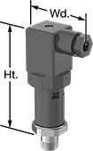 |
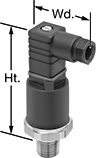
Pressure Range, psi | Max. Continuous Pressure, psi | Max. Short-Term Pressure, psi | Input Voltage, V DC | Electrical Connection Thread Size | Ht. | Wd. | Enclosure Rating | Certification | For Use With | Accuracy | Housing Material | Connection Material | Temp. Range, ° F | Each | |||
|---|---|---|---|---|---|---|---|---|---|---|---|---|---|---|---|---|---|
1/4 NPT Male Pipe Connection | |||||||||||||||||
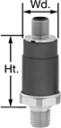
| 0 to 10,000 | 10,000 | 12,000 | 9 to 36 | PG-9 | 3 7/16" | 1 5/16" | IP65, NEMA 4X | UL Recognized Component, C-UL Recognized Component, CE Marked | Air Argon Diesel Fuel Gasoline Hydraulic Fluid Nitrogen Water | ±1.0% | Glass-Filled Nylon | 304 Stainless Steel | -40 to 255 | 3196K612 | 0000000 | ||
 |
Pressure Transmitters | Pressure Transmitters with Calibration Certificate Traceable to NIST | ||||||||||||||||||
|---|---|---|---|---|---|---|---|---|---|---|---|---|---|---|---|---|---|---|---|
Pressure Range, psi | Max. Continuous Pressure, psi | Max. Short-Term Pressure, psi | Input Voltage, V DC | Electrical Connection Thread Size | Ht. | Wd. | Enclosure Rating | Certification | For Use With | Accuracy | Housing Material | Connection Material | Temp. Range, ° F | Each | Each | ||||
1/8 NPT Male Pipe Connection | |||||||||||||||||||
| 0 to 10,000 | 10,000 | 12,000 | 9 to 36 | PG-7 | 2 5/8" | 1 3/8" | IP65, NEMA 4X | UL Recognized Component, C-UL Recognized Component, CE Marked | Air Argon Diesel Fuel Gasoline Hydraulic Fluid Nitrogen Water | ±1.0% | Glass-Filled Nylon | 304 Stainless Steel | -40 to 255 | 3196K389 | 0000000 | ——— | 0 | ||
1/4 NPT Male Pipe Connection | |||||||||||||||||||
| 0 to 10,000 | 10,000 | 12,000 | 9 to 36 | PG-7 | 2 5/8" | 1 3/8" | IP65, NEMA 4X | UL Recognized Component, C-UL Recognized Component, CE Marked | Air Argon Diesel Fuel Gasoline Hydraulic Fluid Nitrogen Water | ±1.0% | Glass-Filled Nylon | 304 Stainless Steel | -40 to 255 | 3196K852 | 000000 | 3196K872 | 0000000 | ||
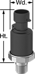 |
Pressure Range, psi | Max. Continuous Pressure, psi | Max. Short-Term Pressure, psi | Input Voltage, V DC | Ht. | Wd. | Enclosure Rating | Certification | For Use With | Accuracy | Housing Material | Connection Material | Temp. Range, ° F | Each | |||
|---|---|---|---|---|---|---|---|---|---|---|---|---|---|---|---|---|
1/4 NPT Male Pipe Connection | ||||||||||||||||
| 0 to 10,000 | 10,000 | 12,000 | 9 to 36 | 2 1/16" | 1 1/16" | IP67, NEMA 4X | UL Recognized Component, C-UL Recognized Component, CE Marked | Air Argon Diesel Fuel Gasoline Hydraulic Fluid Nitrogen Water | ±1.0% | Glass-Filled Nylon | 304 Stainless Steel | -40 to 255 | 3196K453 | 0000000 | ||
 |
Pressure Range, psi | Max. Continuous Pressure, psi | Max. Short-Term Pressure, psi | Input Voltage, V DC | Ht. | Wd. | Enclosure Rating | Certification | For Use With | Accuracy | Housing Material | Connection Material | Temp. Range, ° F | Each | |||
|---|---|---|---|---|---|---|---|---|---|---|---|---|---|---|---|---|
1/4 NPT Male Pipe Connection | ||||||||||||||||
| 0 to 10,000 | 10,000 | 12,000 | 9 to 36 | 2 1/16" | 1 1/16" | IP67, NEMA 4X | UL Recognized Component, C-UL Recognized Component, CE Marked | Air Argon Diesel Fuel Gasoline Hydraulic Fluid Nitrogen Water | ±1.0% | Glass-Filled Nylon | 304 Stainless Steel | -40 to 255 | 3196K466 | 0000000 | ||
|
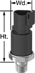
Pressure Range, psi | Max. Continuous Pressure, psi | Max. Short-Term Pressure, psi | Input Voltage, V DC | Ht. | Wd. | Enclosure Rating | Certification | For Use With | Accuracy | Housing Material | Connection Material | Temp. Range, ° F | Each | |||
|---|---|---|---|---|---|---|---|---|---|---|---|---|---|---|---|---|
1/4 NPT Male Pipe Connection | ||||||||||||||||
| 0 to 10,000 | 10,000 | 12,000 | 9 to 36 | 1 15/16" | 15/16" | IP67, NEMA 4X | UL Recognized Component, C-UL Recognized Component, CE Marked | Air Argon Diesel Fuel Gasoline Hydraulic Fluid Nitrogen Water | ±1.0% | Glass-Filled Nylon | 304 Stainless Steel | -40 to 255 | 3196K528 | 0000000 | ||
|
Pressure Range, psi | Max. Continuous Pressure, psi | Max. Short-Term Pressure, psi | Input Voltage, V DC | Ht. | Wd. | Enclosure Rating | Certification | For Use With | Accuracy | Housing Material | Connection Material | Temp. Range, ° F | Each | |||
|---|---|---|---|---|---|---|---|---|---|---|---|---|---|---|---|---|
1/4 NPT Male Pipe Connection | ||||||||||||||||
| 0 to 10,000 | 10,000 | 12,000 | 9 to 36 | 1 15/16" | 15/16" | IP67, NEMA 4X | UL Recognized Component, C-UL Recognized Component, CE Marked | Air Argon Diesel Fuel Gasoline Hydraulic Fluid Nitrogen Water | ±1.0% | Glass-Filled Nylon | 304 Stainless Steel | -40 to 255 | 3196K543 | 0000000 | ||
|
Pressure Range, psi | Max. Continuous Pressure, psi | Max. Short-Term Pressure, psi | Input Voltage, V DC | Ht. | Wd. | Enclosure Rating | Certification | For Use With | Accuracy | Housing Material | Connection Material | Temp. Range, ° F | Each | |||
|---|---|---|---|---|---|---|---|---|---|---|---|---|---|---|---|---|
1/4 NPT Male Pipe Connection | ||||||||||||||||
| 0 to 10,000 | 10,000 | 12,000 | 9 to 36 | 1 11/16" | 7/8" | IP67, NEMA 4X | UL Recognized Component, C-UL Recognized Component, CE Marked | Air Argon Diesel Fuel Gasoline Hydraulic Fluid Nitrogen Water | ±1.0% | Glass-Filled Nylon | 304 Stainless Steel | -40 to 255 | 3196K514 | 0000000 | ||
|
Pressure Range, psi | Max. Continuous Pressure, psi | Max. Short-Term Pressure, psi | Input Voltage, V DC | Electrical Connection Thread Size | Ht. | Wd. | Enclosure Rating | Certification | For Use With | Accuracy | Housing Material | Connection Material | Temp. Range, ° F | Each | |||
|---|---|---|---|---|---|---|---|---|---|---|---|---|---|---|---|---|---|
1/4 NPT Male Pipe Connection | |||||||||||||||||
| 0 to 10,000 | 10,000 | 12,000 | 9 to 36 | PG-9 | 3 7/16" | 1 5/16" | IP65, NEMA 4X | UL Recognized Component, C-UL Recognized Component, CE Marked | Air Argon Diesel Fuel Gasoline Hydraulic Fluid Nitrogen Water | ±1.0% | Glass-Filled Nylon | 304 Stainless Steel | -40 to 255 | 3196K585 | 0000000 | ||
|
Pressure Range, psi | Max. Continuous Pressure, psi | Max. Short-Term Pressure, psi | Input Voltage, V DC | Electrical Connection Thread Size | Ht. | Wd. | Enclosure Rating | Certification | For Use With | Accuracy | Housing Material | Connection Material | Temp. Range, ° F | Each | |||
|---|---|---|---|---|---|---|---|---|---|---|---|---|---|---|---|---|---|
1/4 NPT Male Pipe Connection | |||||||||||||||||
| 0 to 10,000 | 10,000 | 12,000 | 9 to 36 | PG-7 | 2 5/8" | 1 3/8" | IP65, NEMA 4X | UL Recognized Component, C-UL Recognized Component, CE Marked | Air Argon Diesel Fuel Gasoline Hydraulic Fluid Nitrogen Water | ±1.0% | Glass-Filled Nylon | 304 Stainless Steel | -40 to 255 | 3196K349 | 0000000 | ||
|
Pressure Range, psi | Max. Continuous Pressure, psi | Max. Short-Term Pressure, psi | Input Voltage, V DC | Ht. | Wd. | Enclosure Rating | Certification | For Use With | Accuracy | Housing Material | Connection Material | Temp. Range, ° F | Each | |||
|---|---|---|---|---|---|---|---|---|---|---|---|---|---|---|---|---|
1/4 NPT Male Pipe Connection | ||||||||||||||||
| 0 to 10,000 | 10,000 | 12,000 | 14 to 36 | 1 15/16" | 15/16" | IP67, NEMA 4X | UL Recognized Component, C-UL Recognized Component, CE Marked | Air Argon Diesel Fuel Gasoline Hydraulic Fluid Nitrogen Water | ±1.0% | Glass-Filled Nylon | 304 Stainless Steel | -40 to 255 | 3196K557 | 0000000 | ||
|
Pressure Range, psi | Max. Continuous Pressure, psi | Max. Short-Term Pressure, psi | Input Voltage, V DC | Ht. | Wd. | Enclosure Rating | Certification | For Use With | Accuracy | Housing Material | Connection Material | Temp. Range, ° F | Each | |||
|---|---|---|---|---|---|---|---|---|---|---|---|---|---|---|---|---|
1/4 NPT Male Pipe Connection | ||||||||||||||||
| 0 to 10,000 | 10,000 | 12,000 | 14 to 36 | 1 11/16" | 15/16" | IP67, NEMA 4X | UL Recognized Component, C-UL Recognized Component, CE Marked | Air Argon Diesel Fuel Gasoline Hydraulic Fluid Nitrogen Water | ±1.0% | Glass-Filled Nylon | 304 Stainless Steel | -40 to 255 | 3196K336 | 0000000 | ||
|
Pressure Range, psi | Max. Continuous Pressure, psi | Max. Short-Term Pressure, psi | Input Voltage, V DC | Electrical Connection Thread Size | Ht. | Wd. | Enclosure Rating | Certification | For Use With | Accuracy | Housing Material | Connection Material | Temp. Range, ° F | Each | |||
|---|---|---|---|---|---|---|---|---|---|---|---|---|---|---|---|---|---|
1/4 NPT Male Pipe Connection | |||||||||||||||||
| 0 to 10,000 | 10,000 | 12,000 | 14 to 36 | PG-9 | 3 7/16" | 1 5/16" | IP65, NEMA 4X | UL Recognized Component, C-UL Recognized Component, CE Marked | Air Argon Diesel Fuel Gasoline Hydraulic Fluid Nitrogen Water | ±1.0% | Glass-Filled Nylon | 304 Stainless Steel | -40 to 255 | 3196K598 | 0000000 | ||
|
Pressure Transmitters | Pressure Transmitters with Calibration Certificate Traceable to NIST | ||||||||||||||||||
|---|---|---|---|---|---|---|---|---|---|---|---|---|---|---|---|---|---|---|---|
Pressure Range, psi | Max. Continuous Pressure, psi | Max. Short-Term Pressure, psi | Input Voltage, V DC | Electrical Connection Thread Size | Ht. | Wd. | Enclosure Rating | Certification | For Use With | Accuracy | Housing Material | Connection Material | Temp. Range, ° F | Each | Each | ||||
1/4 NPT Male Pipe Connection | |||||||||||||||||||
| 0 to 10,000 | 10,000 | 12,000 | 14 to 36 | PG-7 | 2 5/8" | 1 3/8" | IP65, NEMA 4X | UL Recognized Component, C-UL Recognized Component, CE Marked | Air Argon Diesel Fuel Gasoline Hydraulic Fluid Nitrogen Water | ±1.0% | Glass-Filled Nylon | 304 Stainless Steel | -40 to 255 | 3196K862 | 0000000 | 3196K882 | 0000000 | ||
Vibration-Resistant Pressure Test Gauges
| |
Bottom Connection/Flange Mount | Bottom Connection |
Pressure, psi | Mounting Holes | Bottom Connection/Flange Mount | |||||||||||||
|---|---|---|---|---|---|---|---|---|---|---|---|---|---|---|---|
Range | Graduations | Numeric Increments | Accuracy | Environment Temp. Range, ° F | Process Temp. Range, ° F | Case Color | Mounting Fasteners Included | Dia. | No. of | For Use With | Features | Each | |||
NPT Male | |||||||||||||||
4 1/2" Diameter Dial—1/2 Pipe Size | |||||||||||||||
| 0 to 10,000 | 100 | 1,000 | ±0.5% Full Scale (Grade 2A) | 0 to 150 | 0 to 210 | Black | No | 1/4" | 3 | Air, Diesel Fuel, Gasoline, Hydraulic Fluid, Natural Gas, Water | Glow-in-the-Dark Dial, Safety Case | 4063K176 | 0000000 | ||
| 0 to 10,000 | 100 | 1,000 | ±0.5% Full Scale (Grade 2A) | 0 to 150 | 0 to 210 | Black | No | 1/4" | 3 | Air, Diesel Fuel, Gasoline, Hydraulic Fluid, Natural Gas, Water | Safety Case | 4065K826 | 000000 | ||
NPT Male—Calibration Certificate Traceable to NIST | |||||||||||||||
4 1/2" Diameter Dial—1/2 Pipe Size | |||||||||||||||
| 0 to 10,000 | 100 | 1,000 | ±0.5% Full Scale (Grade 2A) | 0 to 150 | 0 to 210 | Black | No | 1/4" | 3 | Air, Diesel Fuel, Gasoline, Hydraulic Fluid, Natural Gas, Water | Glow-in-the-Dark Dial, Safety Case | 4063K337 | 000000 | ||
| 0 to 10,000 | 100 | 1,000 | ±0.5% Full Scale (Grade 2A) | 0 to 150 | 0 to 210 | Black | No | 1/4" | 3 | Air, Diesel Fuel, Gasoline, Hydraulic Fluid, Natural Gas, Water | Safety Case | 4065K246 | 000000 | ||
 | |
Bottom Connection/Flange Mount | Bottom Connection |
Pressure | Mounting Holes | Bottom Connection/Flange Mount | |||||||||||||
|---|---|---|---|---|---|---|---|---|---|---|---|---|---|---|---|
Range | Graduations | Numeric Increments | Accuracy | Environment Temp. Range, ° F | Process Temp. Range, ° F | Case Color | Mounting Fasteners Included | Dia. | No. of | For Use With | Features | Each | |||
NPT Male | |||||||||||||||
4 1/2" Diameter Dial—1/2 Pipe Size | |||||||||||||||
| 0 psi to 10,000 psi 0 kPa to 68,500 kPa | 100 psi, 500 kPa | 1,000 psi; 5,000 kPa | ±0.5% Full Scale (Grade 2A) | 0 to 150 | 0 to 210 | Black | No | 1/4" | 3 | Air, Diesel Fuel, Gasoline, Hydraulic Fluid, Natural Gas, Water | Safety Case | 4065K625 | 0000000 | ||
NPT Male—Calibration Certificate Traceable to NIST | |||||||||||||||
4 1/2" Diameter Dial—1/2 Pipe Size | |||||||||||||||
| 0 psi to 10,000 psi 0 kPa to 68,500 kPa | 100 psi, 500 kPa | 1,000 psi; 5,000 kPa | ±0.5% Full Scale (Grade 2A) | 0 to 150 | 0 to 210 | Black | No | 1/4" | 3 | Air, Diesel Fuel, Gasoline, Hydraulic Fluid, Natural Gas, Water | Safety Case | 4065K186 | 000000 | ||
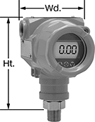
High-Accuracy Pressure Transmitters
 |
Transmitters with Calibration Certificate Traceable to NIST | ||||||||||||||||
|---|---|---|---|---|---|---|---|---|---|---|---|---|---|---|---|---|
Pressure Range, psi | Max. Continuous Pressure, psi | Max. Short-Term Pressure, psi | Input Voltage, V DC | Pipe Size | Ht. | Wd. | Temp. Range, ° F | Enclosure Rating | For Use With | Pipe Connection | Housing Material | Connection Material | Each | |||
4 mA to 20 mA Output Signal—Wire Lead Connection | ||||||||||||||||
±0.25% Accuracy | ||||||||||||||||
| 0 to 10,000 | 10,000 | 12,500 | 9 to 30 | 1/4 | 2 1/8" | 1" | -40 to 255 | IP67, NEMA 4X | Air Argon Diesel Fuel Gasoline Hydraulic Fluid Nitrogen Water | NPT Male | 304 Stainless Steel | 17-4 PH Stainless Steel | 3920N21 | 0000000 | ||
Easy-Setup Pressure Transmitters
 |
Pressure Range, psi | Max. Continuous Pressure, psi | Max. Short-Term Pressure, psi | Input Voltage, V DC | Ht. | Wd. | Enclosure Rating | Certification | For Use With | Accuracy | Housing Material | Connection Material | Temp. Range, ° F | Each | |||
|---|---|---|---|---|---|---|---|---|---|---|---|---|---|---|---|---|
HART Communication Protocol | ||||||||||||||||
1/2 NPT Male Pipe Connection | ||||||||||||||||
| 0 to 10,000 | 10,000 | 16,000 | 11 to 55 | 5 1/8" | 3 21/32" | IP66, NEMA 4X | CE Marked | Air Argon Hydraulic Fluid Nitrogen Water | ±0.075% | Aluminum | 316 Stainless Steel, Hastelloy Nickel | -40 to 180 | 3262N18 | 0000000 | ||
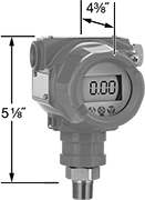
Hazardous-Location Easy-Setup Pressure Transmitters
 |
Pressure Range, psi | Max. Continuous Pressure, psi | Max. Short-Term Pressure, psi | Input Voltage, V DC | Ht. | Wd. | Hazardous Location Rating | Enclosure Rating | Certification | For Use With | Accuracy | Housing Material | Connection Material | Temp. Range, ° F | Each | |||
|---|---|---|---|---|---|---|---|---|---|---|---|---|---|---|---|---|---|
HART Communication Protocol | |||||||||||||||||
1/2 NPT Male Pipe Connection | |||||||||||||||||
| 0 to 10,000 | 10,000 | 16,000 | 11 to 55 | 5 1/8" | 4 3/8" | NEC Class I Divisions 1, 2 Groups A, B, C, D | IP66, NEMA 4X | CE Marked, CSA Certified | Air Argon Hydraulic Fluid Nitrogen Water | ±0.075% | Aluminum | Hastelloy Nickel | -40 to 180 | 8874N18 | 0000000 | ||
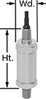
Hazardous-Location Pressure Transmitters
 |
Pressure Range, psi | Max. Continuous Pressure, psi | Max. Short-Term Pressure, psi | Input Voltage, V DC | Ht. | Wd. | Hazardous Location Rating | Enclosure Rating | Certification | For Use With | Accuracy | Housing Material | Connection Material | Temp. Range, ° F | Each | |||
|---|---|---|---|---|---|---|---|---|---|---|---|---|---|---|---|---|---|
1/4 NPT Male Pipe Connection | |||||||||||||||||
| 0 to 10,000 | 10,000 | 17,500 | 10 to 30 | 3 5/16" | 1 1/16" | NEC Class I Divisions 1, 2 Groups A, B, C, D | IP67 | CE Marked, CSA Certified, FM Approved | Air Argon Diesel Fuel Gasoline Hydraulic Fluid Nitrogen Water | ±0.25% | 316 Stainless Steel | 316 Stainless Steel | -40 to 130 | 5484N18 | 0000000 | ||
Economy Pressure Transmitters
 |
Pressure Range, psi | Max. Continuous Pressure, psi | Max. Short-Term Pressure, psi | Input Voltage, V DC | Ht. | Wd. | Enclosure Rating | Certification | For Use With | Accuracy | Housing Material | Connection Material | Temp. Range, ° F | Each | |||
|---|---|---|---|---|---|---|---|---|---|---|---|---|---|---|---|---|
1/4 NPT Male Pipe Connection | ||||||||||||||||
| 0 to 10,000 | 10,000 | 12,000 | 12 to 36 | 1 13/16" | 15/16" | IP65 | CE Marked | Air Argon Diesel Fuel Hydraulic Fluid Nitrogen Water | ±1.5% | 304 Stainless Steel | 304 Stainless Steel | -20 to 220 | 6017N23 | 0000000 | ||
