Filter by
Length
Electrical Connection

Heat Cable Type
Watt Density
Maximum Temperature
Temperature Control Type
Export Control Classification Number (ECCN)
DFARS Specialty Metals

About Heating Tape
Compare self-regulating and constant-watt heating tape. Plus, learn how to install it and how to calculate your power needs.
Self-Regulating Heating Tape for Pipes and Tubes
 |
Hardwire |
 |
Plug In |
5-15 |
When the ambient temperature changes, these heaters automatically adjust the heat output along the length of their cable. Also known as self-regulating heat cable, they don’t require a separate temperature switch or controller. These heaters use their full wattage for more heat when surrounding temperatures are low and reduce their wattage when temperatures are high. Heat output can simultaneously vary at multiple points along a single cable. They’re often used to maintain liquid temperature and viscosity and provide freeze protection in pipe and tube systems. All are CSA certified for pipe freeze protection and are rated for outdoor use. Heaters can overlap without creating hot spots or risking burnout. A protective rubber cover provides corrosion resistance and durability.
Note: Only install these heaters in accessible locations; do not install them behind walls, underground, or in other difficult-to-access areas. Use fiberglass tape or heat-transfer putty to install them directly on surfaces that are free of dirt, grease, and rough edges. Do not use electrical tape, duct tape, metal bands, or wire. To prevent heat loss and protect heaters from moisture and corrosion, wrap them with fiberglass insulation.
Plug In—Heaters with a plug are also CSA certified for roof and gutter de-icing applications. The plug has an indicator light that shows when the system has power.
Watt Density, W/ft | |||||||||||||||||
|---|---|---|---|---|---|---|---|---|---|---|---|---|---|---|---|---|---|
Lg., ft. | Wattage, W | @40°F | @80°F | @100°F | Current, amp | Wd. | Thk. | Environment Temp. Range, ° F | NEMA Type | Cord Lg., ft. | Cable Cover Material | For Surface Material | For Use Outdoors | Each | |||
Hardwire | |||||||||||||||||
240V AC, Single Phase | |||||||||||||||||
| 6 | 36 | 6 | 3 | 1.5 | 0.15 | 7/16" | 1/4" | -40 to 150 | — | 6 | Rubber | Metal, Plastic | Yes | 3580K71 | 0000000 | ||
| 12 | 72 | 6 | 3 | 1.5 | 0.3 | 7/16" | 1/4" | -40 to 150 | — | 6 | Rubber | Metal, Plastic | Yes | 3580K72 | 000000 | ||
| 18 | 108 | 6 | 3 | 1.5 | 0.45 | 7/16" | 1/4" | -40 to 150 | — | 6 | Rubber | Metal, Plastic | Yes | 3580K73 | 000000 | ||
| 24 | 144 | 6 | 3 | 1.5 | 0.6 | 7/16" | 1/4" | -40 to 150 | — | 6 | Rubber | Metal, Plastic | Yes | 3580K74 | 000000 | ||
Plug In—Straight-Blade | |||||||||||||||||
120V AC, Single Phase | |||||||||||||||||
| 6 | 36 | 6 | 3 | 1.5 | 0.3 | 7/16" | 1/4" | -40 to 150 | 5-15 | 6 | Rubber | Metal, Plastic | Yes | 3580K61 | 000000 | ||
| 12 | 72 | 6 | 3 | 1.5 | 0.6 | 7/16" | 1/4" | -40 to 150 | 5-15 | 6 | Rubber | Metal, Plastic | Yes | 3580K62 | 000000 | ||
| 18 | 108 | 6 | 3 | 1.5 | 0.9 | 7/16" | 1/4" | -40 to 150 | 5-15 | 6 | Rubber | Metal, Plastic | Yes | 3580K63 | 000000 | ||
| 24 | 144 | 6 | 3 | 1.5 | 1.2 | 7/16" | 1/4" | -40 to 150 | 5-15 | 6 | Rubber | Metal, Plastic | Yes | 3580K64 | 000000 | ||
| 50 | 300 | 6 | 3 | 1.5 | 2.5 | 7/16" | 1/4" | -40 to 150 | 5-15 | 6 | Rubber | Metal, Plastic | Yes | 3580K65 | 000000 | ||
| 75 | 450 | 6 | 3 | 1.5 | 3.75 | 7/16" | 1/4" | -40 to 150 | 5-15 | 6 | Rubber | Metal, Plastic | Yes | 3580K66 | 000000 | ||
| 100 | 600 | 6 | 3 | 1.5 | 5 | 7/16" | 1/4" | -40 to 150 | 5-15 | 6 | Rubber | Metal, Plastic | Yes | 3580K67 | 000000 | ||
Cut-to-Length Self-Regulating Heating Tape for Pipes and Tubes
 |
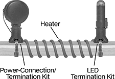
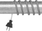
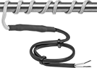
Shown with LED Termination Kit |
 |
Shown with Power-Connection/Termination Kit |
Also known as self-regulating heat cable, these heaters automatically adjust heat output at different points along their length to account for differences in environmental temperature. They output their full wattage where temperature is low and heat is needed. Where it’s warmer, they output reduced wattage. They’re often used to maintain liquid temperature and viscosity and provide freeze protection in pipe and tube systems. Heaters can be overlapped without creating hot spots or risking burnout. All require a power connection/termination kit (sold separately).
Note: Only install these heaters in accessible locations; do not install them behind walls, underground, or in other difficult-to-access areas. Use fiberglass tape or heat-transfer putty to install them directly on surfaces that are free of dirt, grease, and rough edges. Do not use electrical tape, duct tape, metal bands, or wire. To prevent heat loss and protect heaters from moisture and corrosion, wrap them with fiberglass insulation.
Heating Tape
 |
Watt Density, W/ft | Per Ft. | |||||||||||||
|---|---|---|---|---|---|---|---|---|---|---|---|---|---|---|
@50°F | @100°F | @150°F | Wd. | Thk. | Max. Lg., ft. | Environment Temp. Range, ° F | Electrical Connection Type | For Surface Material | For Use Outdoors | 1-99 | 100-Up | |||
150° F Maximum Heat Output | ||||||||||||||
120V AC, Single Phase | ||||||||||||||
| 3 | 1 | 0.5 | 1/2" | 3/16" | 500 | -60 to 185 | Hardwire | Metal, Plastic | No | 3597K11 | 00000 | 00000 | ||
| 5 | 2.5 | 1 | 1/2" | 3/16" | 500 | -60 to 185 | Hardwire | Metal, Plastic | No | 3597K12 | 0000 | 0000 | ||
| 8 | 4.5 | 1.7 | 1/2" | 3/16" | 500 | -60 to 185 | Hardwire | Metal, Plastic | No | 3597K13 | 0000 | 0000 | ||
| 10 | 5.5 | 2 | 1/2" | 3/16" | 500 | -60 to 185 | Hardwire | Metal, Plastic | No | 3597K14 | 00000 | 0000 | ||
240V AC, Single Phase | ||||||||||||||
| 3 | 1 | 0.5 | 1/2" | 3/16" | 500 | -60 to 185 | Hardwire | Metal, Plastic | No | 3597K15 | 0000 | 0000 | ||
| 5 | 2.5 | 1 | 1/2" | 3/16" | 500 | -60 to 185 | Hardwire | Metal, Plastic | No | 3597K16 | 0000 | 0000 | ||
| 8 | 4.5 | 1.7 | 1/2" | 3/16" | 500 | -60 to 185 | Hardwire | Metal, Plastic | No | 3597K17 | 0000 | 0000 | ||
| 10 | 5.5 | 2 | 1/2" | 3/16" | 500 | -60 to 185 | Hardwire | Metal, Plastic | No | 3597K18 | 00000 | 0000 | ||
Plastic Cable Cover
 |
Heaters with a plastic cable cover are rated for use in hazardous locations. They are also more corrosion resistant and durable than heaters without a cable cover.
Watt Density, W/ft | Per Ft. | ||||||||||||||
|---|---|---|---|---|---|---|---|---|---|---|---|---|---|---|---|
@50°F | @100°F | @150°F | Wd. | Thk. | Max. Lg., ft. | Environment Temp. Range, ° F | Electrical Connection Type | For Surface Material | Hazardous Location Rating | For Use Outdoors | 1-99 | 100-Up | |||
150° F Maximum Heat Output | |||||||||||||||
120V AC, Single Phase | |||||||||||||||
| 3 | 1.5 | 0.2 | 9/16" | 1/4" | 500 | -60 to 185 | Hardwire | Metal, Plastic | Ex E II NEC Class I Divisions 1, 2 Groups A, B, C, D NEC Class II Divisions 1, 2 Groups E, F, G NEC Class III Divisions 1, 2 AEx E II | No | 3597K19 | 000000 | 00000 | ||
| 5 | 2.5 | 1 | 9/16" | 1/4" | 500 | -60 to 185 | Hardwire | Metal, Plastic | Ex E II NEC Class I Divisions 1, 2 Groups A, B, C, D NEC Class II Divisions 1, 2 Groups E, F, G NEC Class III Divisions 1, 2 AEx E II | No | 3597K21 | 00000 | 0000 | ||
| 8 | 4.5 | 1.8 | 9/16" | 1/4" | 500 | -60 to 185 | Hardwire | Metal, Plastic | Ex E II NEC Class I Divisions 1, 2 Groups A, B, C, D NEC Class II Divisions 1, 2 Groups E, F, G NEC Class III Divisions 1, 2 AEx E II | No | 3597K22 | 00000 | 0000 | ||
| 10 | 5.7 | 2.1 | 9/16" | 1/4" | 500 | -60 to 185 | Hardwire | Metal, Plastic | Ex E II NEC Class I Divisions 1, 2 Groups A, B, C, D NEC Class II Divisions 1, 2 Groups E, F, G NEC Class III Divisions 1, 2 AEx E II | No | 3597K23 | 00000 | 0000 | ||
240V AC, Single Phase | |||||||||||||||
| 8 | 4.5 | 1.8 | 9/16" | 1/4" | 500 | -60 to 185 | Hardwire | Metal, Plastic | Ex E II NEC Class I Divisions 1, 2 Groups A, B, C, D NEC Class II Divisions 1, 2 Groups E, F, G NEC Class III Divisions 1, 2 AEx E II | No | 3597K24 | 00000 | 0000 | ||
| 10 | 5.7 | 2.1 | 9/16" | 1/4" | 500 | -60 to 185 | Hardwire | Metal, Plastic | Ex E II NEC Class I Divisions 1, 2 Groups A, B, C, D NEC Class II Divisions 1, 2 Groups E, F, G NEC Class III Divisions 1, 2 AEx E II | No | 3597K26 | 00000 | 0000 | ||
250° F Maximum Heat Output | |||||||||||||||
120V AC, Single Phase | |||||||||||||||
| 9 | — | 6 | 7/16" | 1/4" | 500 | -75 to 400 | Hardwire | Metal, Plastic | Ex Eb IIC Ex Tb IIIC NEC Class I Divisions 1, 2 Groups A, B, C, D NEC Class II Divisions 1, 2 Groups E, F, G NEC Class III Divisions 1, 2 NEC Zone 1 Groups IIC, IIB, IIA NEC Zone 21 Groups IIIC, IIIB, IIIA AEx Eb IIC Gb AEx Tb IIIC Db | No | 36005K15 | 00000 | 00000 | ||
| 12 | — | 8.5 | 7/16" | 1/4" | 500 | -75 to 400 | Hardwire | Metal, Plastic | Ex Eb IIC Ex Tb IIIC NEC Class I Divisions 1, 2 Groups A, B, C, D NEC Class II Divisions 1, 2 Groups E, F, G NEC Class III Divisions 1, 2 NEC Zone 1 Groups IIC, IIB, IIA NEC Zone 21 Groups IIIC, IIIB, IIIA AEx Eb IIC Gb AEx Tb IIIC Db | No | 36005K16 | 00000 | 00000 | ||
| 15 | — | 11 | 7/16" | 1/4" | 500 | -75 to 400 | Hardwire | Metal, Plastic | Ex Eb IIC Ex Tb IIIC NEC Class I Divisions 1, 2 Groups A, B, C, D NEC Class II Divisions 1, 2 Groups E, F, G NEC Class III Divisions 1, 2 NEC Zone 1 Groups IIC, IIB, IIA NEC Zone 21 Groups IIIC, IIIB, IIIA AEx Eb IIC Gb AEx Tb IIIC Db | No | 36005K17 | 00000 | 00000 | ||
| 20 | — | 15 | 7/16" | 1/4" | 500 | -75 to 400 | Hardwire | Metal, Plastic | Ex Eb IIC Ex Tb IIIC NEC Class I Divisions 1, 2 Groups A, B, C, D NEC Class II Divisions 1, 2 Groups E, F, G NEC Class III Divisions 1, 2 NEC Zone 1 Groups IIC, IIB, IIA NEC Zone 21 Groups IIIC, IIIB, IIIA AEx Eb IIC Gb AEx Tb IIIC Db | No | 36005K18 | 00000 | 00000 | ||
240V AC, Single Phase | |||||||||||||||
| 12 | — | 8.5 | 7/16" | 1/4" | 500 | -75 to 400 | Hardwire | Metal, Plastic | Ex Eb IIC Ex Tb IIIC NEC Class I Divisions 1, 2 Groups A, B, C, D NEC Class II Divisions 1, 2 Groups E, F, G NEC Class III Divisions 1, 2 NEC Zone 1 Groups IIC, IIB, IIA NEC Zone 21 Groups IIIC, IIIB, IIIA AEx Eb IIC Gb AEx Tb IIIC Db | No | 36005K19 | 00000 | 00000 | ||
| 20 | — | 15 | 7/16" | 1/4" | 500 | -75 to 400 | Hardwire | Metal, Plastic | Ex Eb IIC Ex Tb IIIC NEC Class I Divisions 1, 2 Groups A, B, C, D NEC Class II Divisions 1, 2 Groups E, F, G NEC Class III Divisions 1, 2 NEC Zone 1 Groups IIC, IIB, IIA NEC Zone 21 Groups IIIC, IIIB, IIIA AEx Eb IIC Gb AEx Tb IIIC Db | No | 36005K25 | 00000 | 00000 | ||
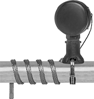
Constant-Wattage Heating Tape with Adjustable Temperature Control for Pipes and Tubes
 | 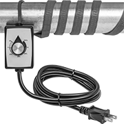 |
Hardwire | Plug In |
Turn the dial to control the percentage of time that these heaters cycle on, from 5% to 100%. Commonly used to thaw pipes, prevent valves from freezing, and heat beakers and flasks in labs, they're good for temporary and occasional use where rapid heating is required but precise temperature control is not.
Unlike self-regulating heaters, these provide a consistent heat output wattage along the entire length of the cable, regardless of the environmental temperature. They do not have a temperature sensor, so you should only use them in areas where you can monitor them with a thermometer (sold separately). Do not use behind walls, underground, or in other difficult-to-access areas.
With a rubber coating, these heaters are both moisture and chemical resistant. Install them onto surfaces that are free of dirt, grease, and rough edges using fiberglass tape or heat-transfer putty. Do not use electrical tape, duct tape, metal bands, or wire. To prevent burnout, make sure they're in full contact with the surface and have no overlap. To prevent heat loss, wrap with fiberglass insulation.
Hardwire—240V AC, Single Phase | Plug In—120V AC, Single Phase | |||||||||||||||
|---|---|---|---|---|---|---|---|---|---|---|---|---|---|---|---|---|
Lg., ft. | Wattage, W | Watt Density, W/ft | Thk. | Environment Temp. Range, ° F | Cord Lg., ft. | Cable Cover Material | For Surface Material | For Use Outdoors | Current, amp | Each | Current, amp | Each | ||||
1/2" Wide | ||||||||||||||||
| 2 | 72 | 36 | 3/16" | -30 to 450 | 6 | Rubber | Metal | No | 0.3 | 3631K31 | 0000000 | 0.6 | 3631K21 | 0000000 | ||
| 4 | 144 | 36 | 3/16" | -30 to 450 | 6 | Rubber | Metal | No | 0.6 | 3631K32 | 000000 | 1.2 | 3631K22 | 000000 | ||
| 6 | 216 | 36 | 3/16" | -30 to 450 | 6 | Rubber | Metal | No | 0.9 | 3631K33 | 000000 | 1.8 | 3631K23 | 000000 | ||
| 8 | 288 | 36 | 3/16" | -30 to 450 | 6 | Rubber | Metal | No | 1.2 | 3631K34 | 000000 | 2.4 | 3631K24 | 000000 | ||
| 10 | 360 | 36 | 3/16" | -30 to 450 | 6 | Rubber | Metal | No | 1.5 | 3631K35 | 000000 | 3 | 3631K25 | 000000 | ||
| 12 | 432 | 36 | 3/16" | -30 to 450 | 6 | Rubber | Metal | No | 1.8 | 3631K102 | 000000 | 3.6 | 3631K101 | 000000 | ||
| 14 | 504 | 36 | 3/16" | -30 to 450 | 6 | Rubber | Metal | No | — | ——— | 0 | 4.2 | 3631K201 | 000000 | ||
| 16 | 576 | 36 | 3/16" | -30 to 450 | 6 | Rubber | Metal | No | — | ——— | 0 | 4.8 | 3631K301 | 000000 | ||
| 18 | 648 | 36 | 3/16" | -30 to 450 | 6 | Rubber | Metal | No | — | ——— | 0 | 5.4 | 3631K401 | 000000 | ||
| 20 | 720 | 36 | 3/16" | -30 to 450 | 6 | Rubber | Metal | No | 3 | 3631K502 | 000000 | 6 | 3631K501 | 000000 | ||
1" Wide | ||||||||||||||||
| 2 | 144 | 72 | 3/16" | -30 to 450 | 6 | Rubber | Metal | No | 0.6 | 3631K71 | 000000 | 1.2 | 3631K61 | 000000 | ||
| 4 | 288 | 72 | 3/16" | -30 to 450 | 6 | Rubber | Metal | No | 1.2 | 3631K72 | 000000 | 2.4 | 3631K62 | 000000 | ||
| 6 | 432 | 72 | 3/16" | -30 to 450 | 6 | Rubber | Metal | No | 1.8 | 3631K73 | 000000 | 3.6 | 3631K63 | 000000 | ||
| 8 | 576 | 72 | 3/16" | -30 to 450 | 6 | Rubber | Metal | No | 2.4 | 3631K74 | 000000 | 4.8 | 3631K64 | 000000 | ||
| 10 | 720 | 72 | 3/16" | -30 to 450 | 6 | Rubber | Metal | No | 3 | 3631K75 | 000000 | 6 | 3631K65 | 000000 | ||
| 12 | 864 | 72 | 3/16" | -30 to 450 | 6 | Rubber | Metal | No | 3.6 | 3631K602 | 000000 | 7.2 | 3631K601 | 000000 | ||
| 14 | 1,008 | 72 | 3/16" | -30 to 450 | 6 | Rubber | Metal | No | — | ——— | 0 | 8.4 | 3631K701 | 000000 | ||
| 16 | 1,152 | 72 | 3/16" | -30 to 450 | 6 | Rubber | Metal | No | — | ——— | 0 | 9.6 | 3631K801 | 000000 | ||
| 18 | 1,296 | 72 | 3/16" | -30 to 450 | 6 | Rubber | Metal | No | — | ——— | 0 | 10.8 | 3631K901 | 000000 | ||
| 20 | 1,440 | 72 | 3/16" | -30 to 450 | 6 | Rubber | Metal | No | 6 | 3631K79 | 000000 | 12 | 3631K69 | 000000 | ||
2" Wide | ||||||||||||||||
| 2 | 288 | 144 | 3/16" | -30 to 450 | 6 | Rubber | Metal | No | — | ——— | 0 | 2.4 | 3631K41 | 000000 | ||
| 4 | 576 | 144 | 3/16" | -30 to 450 | 6 | Rubber | Metal | No | — | ——— | 0 | 4.8 | 3631K42 | 000000 | ||
| 6 | 864 | 144 | 3/16" | -30 to 450 | 6 | Rubber | Metal | No | — | ——— | 0 | 7.2 | 3631K43 | 000000 | ||
| 8 | 1,152 | 144 | 3/16" | -30 to 450 | 6 | Rubber | Metal | No | — | ——— | 0 | 9.6 | 3631K44 | 000000 | ||
| 10 | 1,440 | 144 | 3/16" | -30 to 450 | 6 | Rubber | Metal | No | 6 | 3631K55 | 000000 | 12 | 3631K45 | 000000 | ||
3" Wide | ||||||||||||||||
| 2 | 432 | 216 | 3/16" | -30 to 450 | 6 | Rubber | Metal | No | — | ——— | 0 | 3.6 | 3631K81 | 000000 | ||
| 4 | 864 | 216 | 3/16" | -30 to 450 | 6 | Rubber | Metal | No | — | ——— | 0 | 7.2 | 3631K82 | 000000 | ||
| 6 | 1,296 | 216 | 3/16" | -30 to 450 | 6 | Rubber | Metal | No | — | ——— | 0 | 10.8 | 3631K83 | 000000 | ||
| 8 | 1,440 | 180 | 3/16" | -30 to 450 | 6 | Rubber | Metal | No | — | ——— | 0 | 12 | 3631K84 | 000000 | ||
| 10 | 1,440 | 144 | 3/16" | -30 to 450 | 6 | Rubber | Metal | No | — | ——— | 0 | 12 | 3631K85 | 000000 | ||
| 10 | 1,800 | 180 | 3/16" | -30 to 450 | 6 | Rubber | Metal | No | 7.5 | 3631K95 | 000000 | — | ——— | 0 | ||
Ultra-High Temperature Constant-Wattage Heating Tape for Pipes and Tubes
Lg., ft. | Wattage, W | Watt Density, W/ft | Current, amp | Wd. | Thk. | Environment Temp. Range, ° F | Cord Lg., ft. | Cable Cover Material | For Surface Material | For Use Outdoors | Each | |||
|---|---|---|---|---|---|---|---|---|---|---|---|---|---|---|
Hardwire | ||||||||||||||
 | ||||||||||||||
120V AC, Single Phase | ||||||||||||||
| 2 | 39 | 19.5 | 0.3 | 1/2" | 1/8" | -60 to 1,400 | — | Fiberglass | Ceramic, Glass, Metal | No | 4550T152 | 000000 | ||
| 2 | 104 | 52 | 0.9 | 1/2" | 1/8" | -60 to 1,400 | — | Fiberglass | Ceramic, Glass, Metal | No | 4550T211 | 00000 | ||
| 2 | 156 | 78 | 1.3 | 1/2" | 1/8" | -60 to 1,400 | — | Fiberglass | Ceramic, Glass, Metal | No | 4550T111 | 00000 | ||
| 4 | 78 | 19.5 | 0.7 | 1/2" | 1/8" | -60 to 1,400 | — | Fiberglass | Ceramic, Glass, Metal | No | 4550T162 | 00000 | ||
| 4 | 208 | 52 | 1.7 | 1/2" | 1/8" | -60 to 1,400 | — | Fiberglass | Ceramic, Glass, Metal | No | 4550T221 | 00000 | ||
| 4 | 312 | 78 | 2.6 | 1/2" | 1/8" | -60 to 1,400 | — | Fiberglass | Ceramic, Glass, Metal | No | 4550T121 | 00000 | ||
| 6 | 117 | 19.5 | 1 | 1/2" | 1/8" | -60 to 1,400 | — | Fiberglass | Ceramic, Glass, Metal | No | 4550T172 | 00000 | ||
| 6 | 312 | 52 | 2.6 | 1/2" | 1/8" | -60 to 1,400 | — | Fiberglass | Ceramic, Glass, Metal | No | 4550T231 | 00000 | ||
| 6 | 468 | 78 | 3.9 | 1/2" | 1/8" | -60 to 1,400 | — | Fiberglass | Ceramic, Glass, Metal | No | 4550T131 | 00000 | ||
| 8 | 156 | 19.5 | 1.3 | 1/2" | 1/8" | -60 to 1,400 | — | Fiberglass | Ceramic, Glass, Metal | No | 4550T182 | 000000 | ||
| 8 | 416 | 52 | 3.5 | 1/2" | 1/8" | -60 to 1,400 | — | Fiberglass | Ceramic, Glass, Metal | No | 4550T241 | 000000 | ||
| 8 | 624 | 78 | 5.2 | 1/2" | 1/8" | -60 to 1,400 | — | Fiberglass | Ceramic, Glass, Metal | No | 4550T141 | 000000 | ||
| 10 | 195 | 19.5 | 1.6 | 1/2" | 1/8" | -60 to 1,400 | — | Fiberglass | Ceramic, Glass, Metal | No | 4550T192 | 000000 | ||
| 10 | 520 | 52 | 4.3 | 1/2" | 1/8" | -60 to 1,400 | — | Fiberglass | Ceramic, Glass, Metal | No | 4550T251 | 000000 | ||
| 12 | 234 | 19.5 | 2 | 1/2" | 1/8" | -60 to 1,400 | — | Fiberglass | Ceramic, Glass, Metal | No | 4550T262 | 000000 | ||
| 16 | 312 | 19.5 | 2.6 | 1/2" | 1/8" | -60 to 1,400 | — | Fiberglass | Ceramic, Glass, Metal | No | 4550T272 | 000000 | ||
240V AC, Single Phase | ||||||||||||||
| 2 | 39 | 19.5 | 0.2 | 1/2" | 1/8" | -60 to 1,400 | — | Fiberglass | Ceramic, Glass, Metal | No | 4550T153 | 00000 | ||
| 2 | 104 | 52 | 0.4 | 1/2" | 1/8" | -60 to 1,400 | — | Fiberglass | Ceramic, Glass, Metal | No | 4550T212 | 00000 | ||
| 2 | 156 | 78 | 0.7 | 1/2" | 1/8" | -60 to 1,400 | — | Fiberglass | Ceramic, Glass, Metal | No | 4550T112 | 00000 | ||
| 4 | 78 | 19.5 | 0.3 | 1/2" | 1/8" | -60 to 1,400 | — | Fiberglass | Ceramic, Glass, Metal | No | 4550T163 | 00000 | ||
| 4 | 208 | 52 | 0.9 | 1/2" | 1/8" | -60 to 1,400 | — | Fiberglass | Ceramic, Glass, Metal | No | 4550T222 | 00000 | ||
| 4 | 312 | 78 | 1.3 | 1/2" | 1/8" | -60 to 1,400 | — | Fiberglass | Ceramic, Glass, Metal | No | 4550T122 | 00000 | ||
| 6 | 117 | 19.5 | 0.5 | 1/2" | 1/8" | -60 to 1,400 | — | Fiberglass | Ceramic, Glass, Metal | No | 4550T173 | 00000 | ||
| 6 | 312 | 52 | 1.3 | 1/2" | 1/8" | -60 to 1,400 | — | Fiberglass | Ceramic, Glass, Metal | No | 4550T232 | 00000 | ||
| 6 | 468 | 78 | 2 | 1/2" | 1/8" | -60 to 1,400 | — | Fiberglass | Ceramic, Glass, Metal | No | 4550T132 | 00000 | ||
| 8 | 156 | 19.5 | 0.7 | 1/2" | 1/8" | -60 to 1,400 | — | Fiberglass | Ceramic, Glass, Metal | No | 4550T183 | 000000 | ||
| 8 | 416 | 52 | 1.7 | 1/2" | 1/8" | -60 to 1,400 | — | Fiberglass | Ceramic, Glass, Metal | No | 4550T242 | 000000 | ||
| 8 | 624 | 78 | 2.6 | 1/2" | 1/8" | -60 to 1,400 | — | Fiberglass | Ceramic, Glass, Metal | No | 4550T142 | 000000 | ||
| 10 | 195 | 19.5 | 0.8 | 1/2" | 1/8" | -60 to 1,400 | — | Fiberglass | Ceramic, Glass, Metal | No | 4550T193 | 000000 | ||
| 10 | 520 | 52 | 2.2 | 1/2" | 1/8" | -60 to 1,400 | — | Fiberglass | Ceramic, Glass, Metal | No | 4550T252 | 000000 | ||
| 12 | 234 | 19.5 | 1 | 1/2" | 1/8" | -60 to 1,400 | — | Fiberglass | Ceramic, Glass, Metal | No | 4550T263 | 000000 | ||
| 16 | 312 | 19.5 | 1.3 | 1/2" | 1/8" | -60 to 1,400 | — | Fiberglass | Ceramic, Glass, Metal | No | 4550T273 | 000000 | ||
Plug In—Straight-Blade | ||||||||||||||
 | ||||||||||||||
120V AC, Single Phase | ||||||||||||||
| 2 | 39 | 19.5 | 0.3 | 1/2" | 1/8" | -60 to 1,400 | 2 | Fiberglass | Ceramic, Glass, Metal | No | 4550T151 | 00000 | ||
| 2 | 104 | 52 | 0.9 | 1/2" | 1/8" | -60 to 1,400 | 2 | Fiberglass | Ceramic, Glass, Metal | No | 4550T213 | 00000 | ||
| 2 | 156 | 78 | 1.3 | 1/2" | 1/8" | -60 to 1,400 | 2 | Fiberglass | Ceramic, Glass, Metal | No | 4550T113 | 00000 | ||
| 4 | 78 | 19.5 | 0.7 | 1/2" | 1/8" | -60 to 1,400 | 2 | Fiberglass | Ceramic, Glass, Metal | No | 4550T161 | 00000 | ||
| 4 | 208 | 52 | 1.7 | 1/2" | 1/8" | -60 to 1,400 | 2 | Fiberglass | Ceramic, Glass, Metal | No | 4550T223 | 00000 | ||
| 4 | 312 | 78 | 2.6 | 1/2" | 1/8" | -60 to 1,400 | 2 | Fiberglass | Ceramic, Glass, Metal | No | 4550T123 | 00000 | ||
| 6 | 117 | 19.5 | 1 | 1/2" | 1/8" | -60 to 1,400 | 2 | Fiberglass | Ceramic, Glass, Metal | No | 4550T171 | 00000 | ||
| 6 | 312 | 52 | 2.6 | 1/2" | 1/8" | -60 to 1,400 | 2 | Fiberglass | Ceramic, Glass, Metal | No | 4550T233 | 00000 | ||
| 6 | 468 | 78 | 3.9 | 1/2" | 1/8" | -60 to 1,400 | 2 | Fiberglass | Ceramic, Glass, Metal | No | 4550T133 | 00000 | ||
| 8 | 156 | 19.5 | 1.3 | 1/2" | 1/8" | -60 to 1,400 | 2 | Fiberglass | Ceramic, Glass, Metal | No | 4550T181 | 000000 | ||
| 8 | 416 | 52 | 3.5 | 1/2" | 1/8" | -60 to 1,400 | 2 | Fiberglass | Ceramic, Glass, Metal | No | 4550T243 | 000000 | ||
| 8 | 624 | 78 | 5.2 | 1/2" | 1/8" | -60 to 1,400 | 2 | Fiberglass | Ceramic, Glass, Metal | No | 4550T143 | 000000 | ||
| 10 | 195 | 19.5 | 1.6 | 1/2" | 1/8" | -60 to 1,400 | 2 | Fiberglass | Ceramic, Glass, Metal | No | 4550T191 | 000000 | ||
| 10 | 520 | 52 | 4.3 | 1/2" | 1/8" | -60 to 1,400 | 2 | Fiberglass | Ceramic, Glass, Metal | No | 4550T253 | 000000 | ||
| 12 | 234 | 19.5 | 2 | 1/2" | 1/8" | -60 to 1,400 | 2 | Fiberglass | Ceramic, Glass, Metal | No | 4550T261 | 000000 | ||
| 16 | 312 | 19.5 | 2.6 | 1/2" | 1/8" | -60 to 1,400 | 2 | Fiberglass | Ceramic, Glass, Metal | No | 4550T271 | 000000 | ||
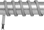
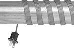
Constant-Wattage Heating Tape with Temperature Control for Pipes and Tubes
 |
5-15 |
A nonadjustable thermostat turns these heaters on when the temperature drops below 38° F and turns them off when the temperature reaches 45° F. Often used to maintain liquid temperature and viscosity and provide freeze protection in pipe and tube systems, they supply the same wattage regardless of the surrounding temperature and are less prone to power surges than self-regulating heaters. To prevent burnout, they should be installed straight along pipes and tubes; they must not be overlapped or spiraled and must be in full contact with the surface being heated. All are rated for outdoor use. The plastic cable cover provides corrosion resistance and durability. Heaters have a plug with an indicator light that shows when the system has power.
Note: Only install these heaters in accessible locations; do not install them behind walls, underground, or in other difficult-to-access areas. Use fiberglass tape or heat-transfer putty to install them directly on surfaces that are free of dirt, grease, and rough edges. Do not use electrical tape, duct tape, metal bands, or wire. To prevent heat loss and protect heaters from moisture and corrosion, wrap them with fiberglass insulation.
Lg., ft. | Wattage, W | Watt Density, W/ft | Current, amp | Wd. | Thk. | Environment Temp. Range, ° F | For Pipe Dia. | NEMA Type | Cord Lg., ft. | Cable Cover Material | For Surface Material | For Use Outdoors | Each | |||
|---|---|---|---|---|---|---|---|---|---|---|---|---|---|---|---|---|
Plug In—Straight-Blade | ||||||||||||||||
120V AC, Single Phase | ||||||||||||||||
| 3 | 21 | 7 | 0.2 | 1/2" | 3/8" | -40 to 155 | 3/4" to 1 1/2" | 5-15 | 2 | Plastic | Metal, Plastic | Yes | 3554K21 | 000000 | ||
| 6 | 42 | 7 | 0.4 | 1/2" | 3/8" | -40 to 155 | 3/4" to 1 1/2" | 5-15 | 2 | Plastic | Metal, Plastic | Yes | 3554K22 | 00000 | ||
| 9 | 63 | 7 | 0.5 | 1/2" | 3/8" | -40 to 155 | 3/4" to 1 1/2" | 5-15 | 2 | Plastic | Metal, Plastic | Yes | 3554K23 | 00000 | ||
| 12 | 84 | 7 | 0.7 | 1/2" | 3/8" | -40 to 155 | 3/4" to 1 1/2" | 5-15 | 2 | Plastic | Metal, Plastic | Yes | 3554K24 | 00000 | ||
| 15 | 105 | 7 | 0.9 | 1/2" | 3/8" | -40 to 155 | 3/4" to 1 1/2" | 5-15 | 2 | Plastic | Metal, Plastic | Yes | 3554K25 | 00000 | ||
| 18 | 126 | 7 | 1.1 | 1/2" | 3/8" | -40 to 155 | 3/4" to 1 1/2" | 5-15 | 2 | Plastic | Metal, Plastic | Yes | 3554K26 | 00000 | ||
| 24 | 168 | 7 | 1.4 | 1/2" | 3/8" | -40 to 155 | 3/4" to 1 1/2" | 5-15 | 2 | Plastic | Metal, Plastic | Yes | 3554K27 | 00000 | ||
| 30 | 210 | 7 | 1.8 | 1/2" | 3/8" | -40 to 155 | 3/4" to 1 1/2" | 5-15 | 2 | Plastic | Metal, Plastic | Yes | 3554K28 | 00000 | ||
| 40 | 280 | 7 | 2.3 | 1/2" | 3/8" | -40 to 155 | 3/4" to 1 1/2" | 5-15 | 2 | Plastic | Metal, Plastic | Yes | 3554K29 | 00000 | ||
| 60 | 420 | 7 | 3.5 | 1/2" | 3/8" | -40 to 155 | 3/4" to 1 1/2" | 5-15 | 2 | Plastic | Metal, Plastic | Yes | 3554K31 | 00000 | ||
| 80 | 560 | 7 | 4.7 | 1/2" | 3/8" | -40 to 155 | 3/4" to 1 1/2" | 5-15 | 2 | Plastic | Metal, Plastic | Yes | 3554K32 | 00000 | ||
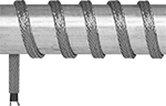
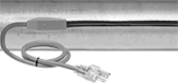
Cut-to-Length Constant-Wattage Heating Tape for Pipes and Tubes
 |
With a cable that supplies the same wattage along the entire length, these heaters remain consistent regardless of the surrounding temperature. All require a temperature switch or controller (sold separately) to regulate heat output. They’re often used to maintain liquid temperature and viscosity and provide freeze protection in pipe and tube systems. To prevent burnout, heaters must not be overlapped and must be in full contact with the surface being heated. All have a plastic cable cover for corrosion resistance and durability. They are FM approved for hazardous locations. A power-connection/termination kit (sold separately) is required.
Note: Only install these heaters in accessible locations; do not install them behind walls, underground, or in other difficult-to-access areas. Use fiberglass tape or heat-transfer putty to install them directly on surfaces that are free of dirt, grease, and rough edges. Do not use electrical tape, duct tape, metal bands, or wire. To prevent heat loss and protect heaters from moisture and corrosion, wrap them with fiberglass insulation.
Per Ft. | ||||||||||||||
|---|---|---|---|---|---|---|---|---|---|---|---|---|---|---|
Watt Density, W/ft | Wd. | Thk. | Max. Lg., ft. | Environment Temp. Range, ° F | Electrical Connection Type | Cable Cover Material | For Surface Material | Hazardous Location Rating | For Use Outdoors | 1-99 | 100-Up | |||
150° F Maximum Heat Output | ||||||||||||||
120V AC, Single Phase | ||||||||||||||
| 2.5 | 1/2" | 11/32" | 500 | -40 to 400 | Hardwire | Plastic | Metal | Ex E II NEC Class I Divisions 1, 2 Groups A, B, C, D NEC Class II Divisions 1, 2 Groups E, F, G NEC Class III Divisions 1, 2 AEx E II | No | 35535K12 | 000000 | 000000 | ||
| 5 | 1/2" | 11/32" | 500 | -40 to 400 | Hardwire | Plastic | Metal | Ex E II NEC Class I Divisions 1, 2 Groups A, B, C, D NEC Class II Divisions 1, 2 Groups E, F, G NEC Class III Divisions 1, 2 AEx E II | No | 35535K13 | 00000 | 00000 | ||
| 8 | 1/2" | 11/32" | 500 | -40 to 400 | Hardwire | Plastic | Metal | Ex E II NEC Class I Divisions 1, 2 Groups A, B, C, D NEC Class II Divisions 1, 2 Groups E, F, G NEC Class III Divisions 1, 2 AEx E II | No | 35535K14 | 00000 | 00000 | ||
| 10 | 1/2" | 11/32" | 500 | -40 to 400 | Hardwire | Plastic | Metal | Ex E II NEC Class I Divisions 1, 2 Groups A, B, C, D NEC Class II Divisions 1, 2 Groups E, F, G NEC Class III Divisions 1, 2 AEx E II | No | 35535K15 | 00000 | 00000 | ||
240V AC, Single Phase | ||||||||||||||
| 5 | 1/2" | 11/32" | 500 | -40 to 400 | Hardwire | Plastic | Metal | Ex E II NEC Class I Divisions 1, 2 Groups A, B, C, D NEC Class II Divisions 1, 2 Groups E, F, G NEC Class III Divisions 1, 2 AEx E II | No | 35535K16 | 00000 | 00000 | ||
480V AC, Single Phase | ||||||||||||||
| 10 | 1/2" | 11/32" | 500 | -40 to 400 | Hardwire | Plastic | Metal | Ex E II NEC Class I Divisions 1, 2 Groups A, B, C, D NEC Class II Divisions 1, 2 Groups E, F, G NEC Class III Divisions 1, 2 AEx E II | No | 35535K17 | 00000 | 00000 | ||
300° F Maximum Heat Output | ||||||||||||||
120V AC, Single Phase | ||||||||||||||
| 10 | 1/2" | 11/32" | 500 | -60 to 500 | Hardwire | Plastic | Metal | Ex E II NEC Class I Divisions 1, 2 Groups A, B, C, D NEC Class II Divisions 1, 2 Groups E, F, G NEC Class III Divisions 1, 2 AEx E II | No | 35535K23 | 00000 | 00000 | ||
| 15 | 1/2" | 11/32" | 500 | -60 to 500 | Hardwire | Plastic | Metal | Ex E II NEC Class I Divisions 1, 2 Groups A, B, C, D NEC Class II Divisions 1, 2 Groups E, F, G NEC Class III Divisions 1, 2 AEx E II | No | 35535K24 | 00000 | 00000 | ||
240V AC, Single Phase | ||||||||||||||
| 10 | 1/2" | 11/32" | 500 | -60 to 500 | Hardwire | Plastic | Metal | Ex E II NEC Class I Divisions 1, 2 Groups A, B, C, D NEC Class II Divisions 1, 2 Groups E, F, G NEC Class III Divisions 1, 2 AEx E II | No | 35535K25 | 00000 | 00000 | ||
| 15 | 1/2" | 11/32" | 500 | -60 to 500 | Hardwire | Plastic | Metal | Ex E II NEC Class I Divisions 1, 2 Groups A, B, C, D NEC Class II Divisions 1, 2 Groups E, F, G NEC Class III Divisions 1, 2 AEx E II | No | 35535K26 | 00000 | 00000 | ||
480V AC, Single Phase | ||||||||||||||
| 10 | 1/2" | 11/32" | 500 | -60 to 500 | Hardwire | Plastic | Metal | NEC Class I Divisions 1, 2 Groups A, B, C, D NEC Class II Divisions 1, 2 Groups E, F, G NEC Class III Divisions 1, 2 NEC Zone 1 Groups IIC, IIB, IIA | No | 35535K27 | 00000 | 00000 | ||
| 15 | 1/2" | 11/32" | 500 | -60 to 500 | Hardwire | Plastic | Metal | NEC Class I Divisions 1, 2 Groups A, B, C, D NEC Class II Divisions 1, 2 Groups E, F, G NEC Class III Divisions 1, 2 NEC Zone 1 Groups IIC, IIB, IIA | No | 35535K28 | 00000 | 00000 | ||
| 20 | 1/2" | 11/32" | 500 | -60 to 500 | Hardwire | Plastic | Metal | NEC Class I Divisions 1, 2 Groups A, B, C, D NEC Class II Divisions 1, 2 Groups E, F, G NEC Class III Divisions 1, 2 NEC Zone 1 Groups IIC, IIB, IIA | No | 35535K29 | 00000 | 00000 | ||
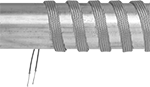
High-Temperature Constant-Wattage Heating Tape for Pipes and Tubes
 |  |
Hardwire | Plug In |
With a maximum heat output of 900° F, these heaters are often used for thawing frozen pipes and rapid spot heating. They supply the same wattage along the entire length of the cable, so they remain consistent regardless of the surrounding temperature. To prevent burnout, heaters must not be overlapped and must be in full contact with the surface being heated.
Note: Only install these heaters in accessible locations; do not install them behind walls, underground, or in other difficult-to-access areas. Use fiberglass tape to install them directly on surfaces that are free of dirt, grease, and rough edges. Do not use electrical tape, duct tape, metal bands, or wire. To prevent heat loss and protect heaters from moisture and corrosion, wrap them with fiberglass insulation.
Hardwire—Hardwire heaters require a temperature switch or controller for regulating heat output.
Plug In—Heaters with a plug require a power controller (sold separately).
Hardwire | Plug In | |||||||||||||||
|---|---|---|---|---|---|---|---|---|---|---|---|---|---|---|---|---|
Lg. | Wattage, W | Watt Density, W/ft | Current, amp | Cable Cover Material | For Surface Material | For Use Outdoors | Thk. | Environment Temp. Range, ° F | Each | Thk. | Environment Temp. Range, ° F | Each | ||||
120V AC, Single Phase | ||||||||||||||||
| 6" | 25 | 50 | 0.2 | Fiberglass | Metal | No | 0.17" | -100 to 900 | 3641K21 | 000000 | — | — | ——— | 0 | ||
| 8" | 35 | 52.5 | 0.3 | Fiberglass | Metal | No | — | — | ——— | 0 | 0.3" | -50 to 900 | 3641K11 | 0000000 | ||
| 12" | 50 | 50 | 0.4 | Fiberglass | Metal | No | 0.17" | -100 to 900 | 3641K22 | 00000 | 0.3" | -50 to 900 | 3641K12 | 000000 | ||
| 24" | 100 | 50 | 0.8 | Fiberglass | Metal | No | 0.17" | -100 to 900 | 3641K23 | 00000 | 0.3" | -50 to 900 | 3641K13 | 000000 | ||
| 36" | 125 | 41.5 | 1 | Fiberglass | Metal | No | 0.17" | -100 to 900 | 3641K24 | 00000 | 0.3" | -50 to 900 | 3641K14 | 000000 | ||
| 60" | 250 | 50 | 2.1 | Fiberglass | Metal | No | 0.17" | -100 to 900 | 3641K25 | 00000 | 0.3" | -50 to 900 | 3641K15 | 000000 | ||
| 96" | 400 | 50 | 3.3 | Fiberglass | Metal | No | 0.17" | -100 to 900 | 3641K26 | 00000 | 0.3" | -50 to 900 | 3641K16 | 000000 | ||
| 120" | 500 | 50 | 4.2 | Fiberglass | Metal | No | 0.17" | -100 to 900 | 3641K27 | 000000 | 0.3" | -50 to 900 | 3641K17 | 000000 | ||
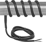
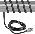
Ultra-Flexible Constant-Wattage Heating Tape for Pipes and Tubes
 |
Hardwire |
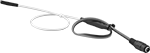 |
Plug In Barrel Connection |
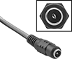 |
Closeup View of 2.1 mm ID Barrel Connector |
Wrap the flexible heating element around small-diameter pipes and tubes or pack it into tight spaces. These heaters maintain a consistent heat output along the entire length of the cable, regardless of the environmental temperature. All require a temperature switch or controller to regulate heat output. They do not produce an electromagnetic field, so they can be used near electronics.
Note: Only install these heaters in accessible locations; do not install them behind walls, underground, or in other difficult-to-access areas. Use fiberglass tape or heat-transfer putty to install them directly on surfaces that are free of dirt, grease, and rough edges. Do not use electrical tape, duct tape, metal bands, or wire. To prevent heat loss and protect heaters from moisture and corrosion, wrap them with fiberglass insulation.
2.1 mm Plug End ID—Pair heaters with a 2.1 mm ID barrel connector with an AC adapter (not included) to power them from a standard AC wall outlet.
Tape | Adapters | |||||||||||||
|---|---|---|---|---|---|---|---|---|---|---|---|---|---|---|
Lg., ft. | Wattage, W | Watt Density | Current, amp | Wd. | Thk. | Environment Temp. Range, ° F | Cable Cover Material | For Surface Material | Each | Each | ||||
Hardwire | ||||||||||||||
120V AC, Single Phase | ||||||||||||||
| 2 1/2 | 36 | 2 W/in² | 0.3 | 0.5" | 0.06" | -75 to 250 | Silicone Rubber | Ceramic, Glass, Metal, Plastic | 2156T101 | 0000000 | ——— | 0 | ||
| 4 | 48 | 2 W/in² | 0.4 | 0.5" | 0.06" | -75 to 250 | Silicone Rubber | Ceramic, Glass, Metal, Plastic | 2156T103 | 000000 | ——— | 0 | ||
| 5 1/2 | 72 | 2 W/in² | 0.6 | 0.5" | 0.06" | -75 to 250 | Silicone Rubber | Ceramic, Glass, Metal, Plastic | 2156T105 | 000000 | ——— | 0 | ||
| 8 | 92 | 2 W/in² | 0.77 | 0.5" | 0.06" | -75 to 250 | Silicone Rubber | Ceramic, Glass, Metal, Plastic | 2156T107 | 000000 | ——— | 0 | ||
240V AC, Single Phase | ||||||||||||||
| 2 1/2 | 36 | 2 W/in² | 0.15 | 0.5" | 0.06" | -75 to 250 | Silicone Rubber | Ceramic, Glass, Metal, Plastic | 2156T102 | 000000 | ——— | 0 | ||
| 4 | 48 | 2 W/in² | 0.2 | 0.5" | 0.06" | -75 to 250 | Silicone Rubber | Ceramic, Glass, Metal, Plastic | 2156T104 | 000000 | ——— | 0 | ||
| 5 1/2 | 72 | 2 W/in² | 0.3 | 0.5" | 0.06" | -75 to 250 | Silicone Rubber | Ceramic, Glass, Metal, Plastic | 2156T106 | 000000 | ——— | 0 | ||
| 8 | 92 | 2 W/in² | 0.38 | 0.5" | 0.06" | -75 to 250 | Silicone Rubber | Ceramic, Glass, Metal, Plastic | 2156T108 | 000000 | ——— | 0 | ||
12V DC | ||||||||||||||
| 1 | 3 | 3 W/ft | 0.3 | 0.12" | 0.06" | -30 to 220 | Polymer Fiber | Metal, Plastic | 2156T12 | 00000 | ——— | 0 | ||
| 2 | 6 | 3 W/ft | 0.5 | 0.12" | 0.06" | -30 to 220 | Polymer Fiber | Metal, Plastic | 2156T22 | 00000 | ——— | 0 | ||
| 3 | 9 | 3 W/ft | 0.8 | 0.12" | 0.06" | -30 to 220 | Polymer Fiber | Metal, Plastic | 2156T32 | 00000 | ——— | 0 | ||
| 4 | 12 | 3 W/ft | 1 | 0.12" | 0.06" | -30 to 220 | Polymer Fiber | Metal, Plastic | 2156T42 | 00000 | ——— | 0 | ||
24V DC | ||||||||||||||
| 2 | 6 | 3 W/ft | 0.3 | 0.12" | 0.06" | -30 to 220 | Polymer Fiber | Metal, Plastic | 2156T52 | 00000 | ——— | 0 | ||
| 4 | 12 | 3 W/ft | 0.5 | 0.12" | 0.06" | -30 to 220 | Polymer Fiber | Metal, Plastic | 2156T62 | 00000 | ——— | 0 | ||
| 6 | 18 | 3 W/ft | 0.8 | 0.12" | 0.06" | -30 to 220 | Polymer Fiber | Metal, Plastic | 2156T72 | 00000 | ——— | 0 | ||
| 8 | 24 | 3 W/ft | 1 | 0.12" | 0.06" | -30 to 220 | Polymer Fiber | Metal, Plastic | 2156T82 | 00000 | ——— | 0 | ||
36V DC | ||||||||||||||
| 3 | 9 | 3 W/ft | 0.3 | 0.12" | 0.06" | -30 to 220 | Polymer Fiber | Metal, Plastic | 2156T13 | 00000 | ——— | 0 | ||
| 6 | 18 | 3 W/ft | 0.5 | 0.12" | 0.06" | -30 to 220 | Polymer Fiber | Metal, Plastic | 2156T14 | 00000 | ——— | 0 | ||
| 9 | 27 | 3 W/ft | 0.8 | 0.12" | 0.06" | -30 to 220 | Polymer Fiber | Metal, Plastic | 2156T15 | 00000 | ——— | 0 | ||
| 12 | 36 | 3 W/ft | 1 | 0.12" | 0.06" | -30 to 220 | Polymer Fiber | Metal, Plastic | 2156T16 | 000000 | ——— | 0 | ||
Plug In—2.1 mm Barrel | ||||||||||||||
12V DC | ||||||||||||||
| 1 | 3 | 3 W/ft | 0.3 | 0.12" | 0.06" | -30 to 220 | Polymer Fiber | Metal, Plastic | 2156T17 | 00000 | 70235K49 | 00000 | ||
| 2 | 6 | 3 W/ft | 0.5 | 0.12" | 0.06" | -30 to 220 | Polymer Fiber | Metal, Plastic | 2156T21 | 00000 | 70235K49 | 0000 | ||
| 3 | 9 | 3 W/ft | 0.8 | 0.12" | 0.06" | -30 to 220 | Polymer Fiber | Metal, Plastic | 2156T31 | 00000 | 70235K96 | 0000 | ||
| 4 | 12 | 3 W/ft | 1 | 0.12" | 0.06" | -30 to 220 | Polymer Fiber | Metal, Plastic | 2156T41 | 00000 | 70235K96 | 0000 | ||
24V DC | ||||||||||||||
| 2 | 6 | 3 W/ft | 0.3 | 0.12" | 0.06" | -30 to 220 | Polymer Fiber | Metal, Plastic | 2156T51 | 00000 | 70235K99 | 00000 | ||
| 4 | 12 | 3 W/ft | 0.5 | 0.12" | 0.06" | -30 to 220 | Polymer Fiber | Metal, Plastic | 2156T61 | 00000 | 70235K99 | 00000 | ||
| 6 | 18 | 3 W/ft | 0.8 | 0.12" | 0.06" | -30 to 220 | Polymer Fiber | Metal, Plastic | 2156T71 | 00000 | 70235K99 | 00000 | ||
| 8 | 24 | 3 W/ft | 1 | 0.12" | 0.06" | -30 to 220 | Polymer Fiber | Metal, Plastic | 2156T81 | 00000 | 70235K99 | 00000 | ||
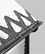
Roof and Gutter Heat Cables
 |  |  |
No. Included | Electrical | |||||||||||
|---|---|---|---|---|---|---|---|---|---|---|---|---|
Lg., ft. | Wattage, W | Watt Density, W/ft | Current, amp | Roof Clips | Downspout Spacers | Connection | No. of Blades | Cord Lg., ft. | Each | |||
120V AC, Single Phase | ||||||||||||
| 30 | 150 | 5 | 1.3 | 19 | 16 | Straight Blade | 3 | 6 | 3546K34 | 000000 | ||
| 60 | 300 | 5 | 2.5 | 38 | 32 | Straight Blade | 3 | 6 | 3546K35 | 00000 | ||
| 80 | 400 | 5 | 3.3 | 57 | 48 | Straight Blade | 3 | 6 | 3546K36 | 00000 | ||
| 100 | 500 | 5 | 4.2 | 76 | 64 | Straight Blade | 3 | 6 | 3546K37 | 00000 | ||
| 120 | 600 | 5 | 5 | 76 | 64 | Straight Blade | 3 | 6 | 3546K44 | 000000 | ||
| 160 | 800 | 5 | 6.7 | 95 | 80 | Straight Blade | 3 | 6 | 3546K45 | 000000 | ||
| 200 | 1,000 | 5 | 8.3 | 133 | 112 | Straight Blade | 3 | 6 | 3546K46 | 000000 | ||
| 240 | 1,200 | 5 | 10 | 152 | 128 | Straight Blade | 3 | 6 | 3546K47 | 000000 | ||
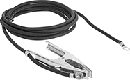
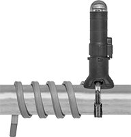
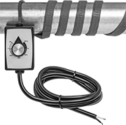
Pipe Thawers
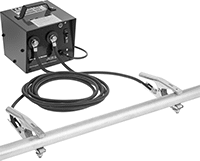 |
Thaw pipe without direct access to or knowing exactly where the frozen section is. Unlike pipe heating tape and cable, you only need to place a clamp on each side of the frozen section, so these thawers can warm pipe that is underground, beneath floors, and behind walls. The heater warms pipe with low-voltage, high-current power so just the outer layers of ice thaw, allowing water pressure to melt the rest of the ice. The frozen section can include turns, so the run of pipe you're thawing can be longer than the distance the cables reach.
Adjustable Output Current—Thawers with an adjustable output current have a switch to flip between low-power usage and high-power usage. The low-power setting works with 15 amp circuit breakers, which are common. The high-power setting can thaw pipes quicker and thaw longer pipes.
Minimum Distance Between Clamps—The clamps must be placed at least 15 ft. apart to prevent tripping a circuit breaker and can reach up to 40 ft. apart.
For Pipe | Cable | Electrical | Housing | |||||||||||||||||
|---|---|---|---|---|---|---|---|---|---|---|---|---|---|---|---|---|---|---|---|---|
Lg., ft. | Size | Minimum Distance Between Clamps, ft. | Output Current | Input Current | Lg., ft. | Cover Material | Environment Temp. Range, ° F | Connection Type | Phase | Wattage, W | Ht. | Wd. | Dp. | Material | For Surface Material | For Use Outdoors | Each | |||
Fixed Output Current | ||||||||||||||||||||
| 15 to 100 | 1/2, 3/4, 1, 1 1/4, 1 1/2 | 15 | 320 amp | 13 amp | 20 | TPE | 0 to 80 | Plug In | Single | 1,560 | 8" | 8" | 8" | Steel | Metal | No | 4336N11 | 000000000 | ||
Adjustable Output Current | ||||||||||||||||||||
| 15 to 175 | 1/2, 3/4, 1, 1 1/4, 1 1/2 | 15 | 320 amp 400 amp | 14 amp 20 amp | 20 | TPE | 0 to 80 | Plug In | Single | 2,400 | 8" | 8" | 8" | Steel | Metal | No | 4336N12 | 00000000 | ||