


Filter by
For Material Thickness


DFARS Specialty Metals
Length
Body Material
Export Control Classification Number (ECCN)
Mount Type
Handle Material
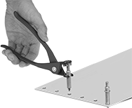
Hole-Grip Panel Alignment Clamps
 |
OD | For Drill Bit Size | For Material Thk. | Holding Cap. | Overall Lg. | Each | |||
|---|---|---|---|---|---|---|---|---|
Steel Body | ||||||||
| 3/32" | 40 Ga. | 0" to 1/4" | Not Rated | 2" | 5099A29 | 00000 | ||
| 3/32" | 40 Ga. | 0" to 1/2" | Not Rated | 2" | 5099A12 | 0000 | ||
| 1/8" | 30 Ga. | 0" to 1/4" | Not Rated | 2" | 5099A32 | 0000 | ||
| 1/8" | 30 Ga. | 0" to 1/2" | Not Rated | 2" | 5099A13 | 0000 | ||
| 5/32" | 20 Ga. | 0" to 1/4" | Not Rated | 2" | 5099A34 | 0000 | ||
| 5/32" | 20 Ga. | 0" to 1/2" | Not Rated | 2" | 5099A14 | 0000 | ||
| 3/16" | 10 Ga. | 0" to 1/4" | Not Rated | 2" | 5099A33 | 0000 | ||
| 3/16" | 10 Ga. | 0" to 1/2" | Not Rated | 2" | 5099A15 | 0000 | ||
| 7/32" | 7/32" | 0" to 1/4" | Not Rated | 2 1/16" | 5099A45 | 0000 | ||
| 7/32" | 7/32" | 0" to 1/2" | Not Rated | 2 7/16" | 5099A46 | 0000 | ||
| 1/4" | 1/4" | 0" to 1/4" | Not Rated | 2" | 5099A31 | 0000 | ||
| 1/4" | 1/4" | 0" to 1/2" | Not Rated | 2 7/16" | 5099A16 | 0000 | ||
Pliers-Activated Spring Panel Alignment Clamps
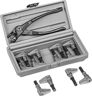
Hole-grip Panel Alignment Clamp Sets
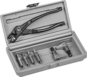 |
Sets include clamps and installation pliers. Insert clamps into drilled holes in sheet material to grip and align while riveting or soldering.
No. of Pieces | Includes | Container Type | Each | ||
|---|---|---|---|---|---|
| 7 | One 2 1/4" Lg. 3/32" OD Steel Hole-Grip Clamp with 1/4" Max. Opening (For No. 40 drill bit size) One 2 1/4" Lg. 1/8" OD Steel Hole-Grip Clamp with 1/4" Max. Opening (For No. 30 drill bit size) One 2 1/4" Lg. 3/16" OD Steel Hole-Grip Clamp with 1/4" Max. Opening (For No. 10 drill bit size) One 2 1/4" Lg. 1/4" OD Steel Hole-Grip Clamp with 1/4" Max. Opening (For 1/4" drill bit size) Two 2 1/8" Lg. Pliers-Activated Spring Clamps with 1/2" Max. Jaw Opening and Aluminum Jaws 7 1/4" Lg. Steel Clamp Installation Pliers | Plastic Case | 5099A21 | 000000 | |
| 51 | Ten 2 1/4" Lg. 3/32" OD Steel Hole-Grip Clamps with 1/4" Max. Opening (For No. 40 drill bit size) Ten 2 1/4" Lg. 1/8" OD Steel Hole-Grip Clamps with 1/4" Max. Opening (For No. 30 drill bit size) Ten 2 1/4" Lg. 5/32" OD Steel Hole-Grip Clamps with 1/4" Max. Opening (For No. 20 drill bit size) Ten 2 1/4" Lg. 3/16" OD Steel Hole-Grip Clamps with 1/4" Max. Opening (For No. 10 drill bit size) Ten 2 1/4" Lg. 1/4" OD Steel Hole-Grip Clamps with 1/4" Max. Opening (For 1/4" drill bit size) 7 1/4" Lg. Steel Clamp Installation Pliers | Plastic Case | 5099A27 | 000000 |
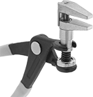
Pliers-Activated Spring Panel Alignment Clamp Sets
 |  |  |
Jaw | |||||||||
|---|---|---|---|---|---|---|---|---|---|
No. of Pieces | Includes | Reach Lg. | Wd. | Material | Container Type | Each | |||
Steel Body | |||||||||
| 13 | Six 2 1/8" Lg. Clamps with 1/2" Max. Opening Six 2 1/2" Lg. Clamps with 3/4" Max. Opening 7 1/4" Lg. Clamp Installation Pliers | 1" | 1/4" | Aluminum | Plastic Case | 5099A25 | 0000000 | ||
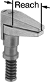
Expandable Cam Handles for Unthreaded Holes
Unthreaded-Plug Mount
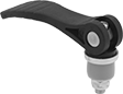 | 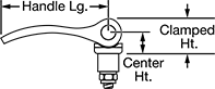 |
Plastic Handle—Made of plastic, these handles resist oil, grease, and solvents.
Handle, mm | ||||||||||||
|---|---|---|---|---|---|---|---|---|---|---|---|---|
For Hole Dia., mm | For Max. Material Thk. | Lg. | Wd. | Ctr. Ht., mm | Clamped Ht., mm | Max. Clamping Force, lbf | Plug Material | Washer Material | Each | |||
Black Plastic Handle | ||||||||||||
| 12 | 5/32" | 72 | 16 | 14 | 22 | 11 | Rubber | Plastic | 1359N11 | 000000 | ||
| 14 | 5/32" | 72 | 16 | 14 | 22 | 13 | Rubber | Plastic | 1359N12 | 00000 | ||
| 16 | 1/4" | 100 | 24 | 16 | 29 | 13 | Rubber | Plastic | 1359N13 | 00000 | ||
| 18 | 1/4" | 100 | 24 | 16 | 29 | 22 | Rubber | Plastic | 1359N14 | 00000 | ||
| 20 | 1/4" | 100 | 24 | 16 | 29 | 22 | Rubber | Plastic | 1359N15 | 00000 | ||
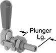
Hole-Mount Push/Pull Toggle Clamps with Locking Handle
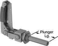 |
Push the lever to lock the handle and prevent accidental opening. Panel mount these clamps through a hole with the included nut, or drill and tap a hole to flush mount. They have an internally threaded plunger to accommodate threaded holding screws and other threaded fixtures (not included).
Push-Only Clamp—Push-only clamps secure when the plunger is fully extended.
Push/Pull Clamp—Push/pull clamps secure in two positions—when the plunger is fully extended and when the plunger is fully retracted.
Plunger | When Clamped | ||||||||||||||
|---|---|---|---|---|---|---|---|---|---|---|---|---|---|---|---|
Holding Cap., lb. | Lg. | Travel | Shape | Dia. | Thread Location | Thread Size | Thread Lg. | Overall Ht. | Overall Lg. | Grip Style | Includes | Each | |||
Push/Pull—Steel | |||||||||||||||
| 450 | 1 1/2" | 1 1/2" | Round | 1/2" | Internal | 5/16"-18 | 1 3/8" | 4 3/16" | 5 1/2" | Cushion | Mounting Nut | 6124A17 | 0000000 | ||
Push Only—Steel | |||||||||||||||
| 750 | 2 3/4" | 2 5/8" | Round | 5/8" | Internal | 3/8"-16 | 1 1/4" | 4 7/8" | 7 1/8" | Cushion | Mounting Nut | 6124A27 | 00000 | ||
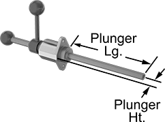
Hole-Mount Push/Pull Toggle Clamps
 |
Panel mount through a hole with the included nut, or drill and tap a hole to flush mount. A pushing or pulling motion holds workpieces from the side. These clamps secure in two positions—when the plunger is fully extended and when the plunger is fully retracted. The plunger is internally threaded to accommodate threaded holding screws and other threaded fixtures (not included).
18-8 Stainless Steel Body—Stainless steel clamps have good corrosion resistance.
Plunger | When Clamped | ||||||||||||||
|---|---|---|---|---|---|---|---|---|---|---|---|---|---|---|---|
Holding Cap., lb. | Lg. | Travel | Shape | Dia. | Thread Location | Thread Size | Thread Lg. | Overall Ht. | Overall Lg. | Grip Style | Includes | Each | |||
Push/Pull—Steel | |||||||||||||||
| 200 | 1 5/16" | 3/4" | Round | 3/8" | Internal | 1/4"-20 | 5/8" | 3 1/8" | 2 7/16" | Cushion | Mounting Nut | 5093A56 | 000000 | ||
| 200 | 1 5/16" | 3/4" | Round | 3/8" | Internal | M6 | 16 mm | 3 1/8" | 2 7/16" | Cushion | Mounting Nut | 5093A42 | 00000 | ||
| 300 | 2 3/16" | 1 1/2" | Round | 7/16" | Internal | 5/16"-18 | 1" | 4 3/16" | 4 1/4" | Cushion | Mounting Nut | 5093A63 | 00000 | ||
| 300 | 2 3/16" | 1 1/2" | Round | 7/16" | Internal | M8 | 25 mm | 4 3/16" | 4 1/4" | Cushion | Mounting Nut | 5093A37 | 00000 | ||
| 450 | 2 1/4" | 1 1/2" | Round | 1/2" | Internal | 5/16"-18 | 1" | 4 1/4" | 5 5/8" | Cushion | Mounting Nut | 5093A81 | 00000 | ||
| 700 | 3 5/8" | 2 5/8" | Round | 5/8" | Internal | M10 | 32 mm | 5 5/8" | 6 11/16" | Cushion | Mounting Nut | 5093A38 | 00000 | ||
Push/Pull—18-8 Stainless Steel | |||||||||||||||
| 200 | 1 5/16" | 3/4" | Round | 3/8" | Internal | 1/4"-20 | 5/8" | 3 1/8" | 2 7/16" | Cushion | Mounting Nut | 5093A72 | 00000 | ||
| 200 | 1 5/16" | 3/4" | Round | 3/8" | Internal | M6 | 16 mm | 3 1/8" | 2 7/16" | Cushion | Mounting Nut | 5093A39 | 00000 | ||
| 300 | 2 3/16" | 1 1/2" | Round | 7/16" | Internal | 5/16"-18 | 1" | 4 3/16" | 4 1/4" | Cushion | Mounting Nut | 5093A69 | 00000 | ||
| 400 | 2 3/16" | 1 1/2" | Round | 7/16" | Internal | M8 | 25 mm | 4 3/16" | 4 1/4" | Cushion | Mounting Nut | 5093A44 | 00000 | ||
| 700 | 3 5/8" | 2 5/8" | Round | 5/8" | Internal | 3/8"-16 | 1 1/4" | 5 5/8" | 6 11/16" | Cushion | Mounting Nut | 5093A76 | 000000 | ||
| 700 | 3 5/8" | 2 5/8" | Round | 5/8" | Internal | M10 | 32 mm | 5 5/8" | 6 11/16" | Cushion | Mounting Nut | 5093A91 | 000000 | ||
Revolving Screw Clamps
Screw Clamps
Clamps
 |
Clamps | Extra-Large Steel Tips | Nonmarring Plastic Tips | Replacement Thumb Screw Retaining Springs | |||||||||||||
|---|---|---|---|---|---|---|---|---|---|---|---|---|---|---|---|---|
Tip | Handle | |||||||||||||||
Thread Size | Lg. | Dia. | Lg. | Ht. | Wd. | Max. Swivel Angle | Material | Each | Each | Each | Each | |||||
| 1/4"-20 | 2" | 3/8" | 1/4" | 5/8" | 1 1/8" | 10° | Steel | 90747A150 | 000000 | 90165A301 | 00000 | 90165A602 | 00000 | 90165A701 | 00000 | |
| 1/4"-20 | 2 3/4" | 3/8" | 1/4" | 5/8" | 1 1/8" | 10° | Steel | 90747A160 | 00000 | 90165A301 | 0000 | 90165A602 | 0000 | 90165A701 | 0000 | |
| 1/4"-20 | 3 1/2" | 3/8" | 1/4" | 5/8" | 1 1/8" | 10° | Steel | 90747A170 | 00000 | 90165A301 | 0000 | 90165A602 | 0000 | 90165A701 | 0000 | |
| 3/8"-16 | 1 5/16" | 1/2" | 1/4" | 1" | 2" | 10° | Steel | 90747A180 | 00000 | 90165A321 | 0000 | 90165A622 | 0000 | 90165A703 | 0000 | |
| 3/8"-16 | 2 13/16" | 1/2" | 1/4" | 1" | 2" | 10° | Steel | 90747A190 | 00000 | 90165A321 | 0000 | 90165A622 | 0000 | 90165A703 | 0000 | |
| 3/8"-16 | 4 5/16" | 1/2" | 1/4" | 1" | 2" | 10° | Steel | 90747A210 | 00000 | 90165A321 | 0000 | 90165A622 | 0000 | 90165A703 | 0000 | |
| 1/2"-13 | 2 1/16" | 5/8" | 3/8" | 1 1/8" | 2 1/2" | 10° | Steel | 90747A220 | 00000 | 90165A331 | 0000 | 90165A632 | 0000 | 90165A704 | 0000 | |
| 1/2"-13 | 3 9/16" | 5/8" | 3/8" | 1 1/8" | 2 1/2" | 10° | Steel | 90747A230 | 00000 | 90165A331 | 0000 | 90165A632 | 0000 | 90165A704 | 0000 | |
| 1/2"-13 | 5 1/16" | 5/8" | 3/8" | 1 1/8" | 2 1/2" | 10° | Steel | 90747A240 | 00000 | 90165A331 | 0000 | 90165A632 | 0000 | 90165A704 | 0000 | |
| 5/8"-11 | 2 3/8" | 3/4" | 1/2" | 1 1/4" | 3" | 10° | Steel | 90747A250 | 00000 | 90165A341 | 0000 | 90165A642 | 0000 | 90165A705 | 0000 | |
| 5/8"-11 | 3 7/8" | 3/4" | 1/2" | 1 1/4" | 3" | 10° | Steel | 90747A260 | 00000 | 90165A341 | 0000 | 90165A642 | 0000 | 90165A705 | 0000 | |
| 5/8"-11 | 5 3/8" | 3/4" | 1/2" | 1 1/4" | 3" | 10° | Steel | 90747A270 | 00000 | 90165A341 | 0000 | 90165A642 | 0000 | 90165A705 | 0000 | |
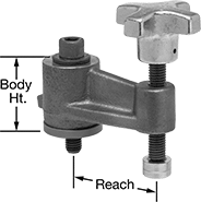
Hole-Mount Adjustable-Travel Push/Pull Clamps
 |
Drill a hole to mount these clamps through a surface and secure the mounting flange with screws. The plunger can be locked at any position along its travel. Push the plunger forward until it contacts the workpiece and then rotate the lever handle to clamp a workpiece from the side. The plunger is internally threaded to accommodate threaded holding screws and other threaded fixtures (not included).
Plunger | When Clamped | ||||||||||||||
|---|---|---|---|---|---|---|---|---|---|---|---|---|---|---|---|
Holding Cap., lb. | Lg. | Ht. | Travel | Shape | Dia. | Thread Location | Thread Size | Thread Lg., mm | Overall Ht. | Overall Lg. | Grip Style | Each | |||
Push/Pull—Steel | |||||||||||||||
| 600 | 7 7/8" | 7/8" | 7 7/8" | Round | 1/2" | Internal | M6 | 12 | 5 1/8" | 13" | Plain | 5010A91 | 0000000 | ||
Hole-Mount Screw Clamps
 |  |
Clamp built into a press |
Also known as press screws, mount these clamps through a drilled hole and turn the crank to move the jaw end of the screw in and out.
Jaw | Handle | Overall | Mounting Hole | |||||||||||
|---|---|---|---|---|---|---|---|---|---|---|---|---|---|---|
Screw Lg. | For Hole Size | Lg. | Wd. | Screw Material | Style | Material | Lg. | Wd. | No. of | Dia. | Mounting Fasteners Included | Each | ||
| 9" | 1" | 1 3/8" | 1 3/8" | Steel | Crank | 18-8 Stainless Steel | 12" | 6" | 4 | 1/8" | No | 5096A14 | 000000 | |
| 12" | 1" | 1 3/8" | 1 3/8" | Steel | Crank | 18-8 Stainless Steel | 14 1/2" | 6" | 4 | 1/8" | No | 5096A16 | 00000 | |
| 18" | 1" | 1 3/8" | 1 3/8" | Steel | Crank | 18-8 Stainless Steel | 20 1/2" | 6" | 4 | 1/8" | No | 5096A18 | 00000 | |
