


Mounting Hole Center-to-Center Mounting HoleCenter-to-Center |
|---|

|
|
|
For Cylinder Mounting Pattern For Cylinder Mounting Pattern |
|---|
|
DFARS (Defense Acquisition Regulations Supplement) DFARS (Defense AcquisitionRegulations Supplement) |
|---|
Maximum Pressure Maximum Pressure |
|---|
|
For Ram Capacity For Ram Capacity |
|---|
|
Maximum Push Force Maximum Push Force |
|---|
|
|
REACH (Registration, Evaluation, Authorization and Restriction of Chemicals) REACH (Registration,Evaluation, Authorization and Restriction of Chemicals) |
|---|
|
RoHS (Restriction of Hazardous Substances) RoHS (Restriction ofHazardous Substances) |
|---|
|
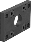
Mounting Plates for Hydraulic Jacks
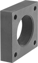
Thread one of these plates onto your ram to mount it at the point of use.
![]() For technical drawings and 3-D models, click on a part number.
For technical drawings and 3-D models, click on a part number.
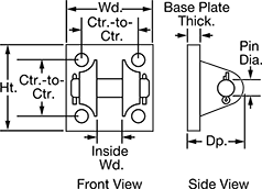
Pivot Brackets for Hydraulic Cylinders
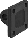

Pivot brackets are designed to be used with clevis rod ends and clevis pins (each component sold separately). When connected to a clevis rod end, they allow a hydraulic cylinder to move in an arc. Do not mount pivot brackets directly onto the cylinder.
![]() For technical drawings and 3-D models, click on a part number.
For technical drawings and 3-D models, click on a part number.
Mounting Hole | |||||||||||
|---|---|---|---|---|---|---|---|---|---|---|---|
| For Pin Dia. | Wd. | Ht. | Dp. | Base Plate Thick. | Dia. | Ctr.-to-Ctr. | Mounting Fasteners Included | Material | For Cylinder Mounting Pattern | Each | |
| 1/2" | 2 1/2" | 2 1/2" | 1 5/8" | 3/8" | 3/8" | 1 5/8" | No | Steel | NFPA Light Duty, NFPA Heavy Duty, JIC Heavy Duty | 00000000 | 000000 |
| 3/4" | 3 1/2" | 3 1/2" | 2 5/8" | 5/8" | 1/2" | 2 9/16" | No | Steel | NFPA Light Duty, NFPA Heavy Duty, JIC Heavy Duty | 00000000 | 00000 |
| 1" | 4 1/2" | 4 1/2" | 3 1/4" | 3/4" | 5/8" | 3 1/4" | No | Steel | NFPA Light Duty, NFPA Heavy Duty, JIC Heavy Duty | 00000000 | 00000 |
| 1 3/8" | 5" | 5" | 4 3/8" | 7/8" | 5/8" | 3 13/16" | No | Iron | NFPA Light Duty, NFPA Heavy Duty, JIC Heavy Duty | 00000000 | 000000 |
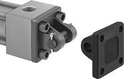
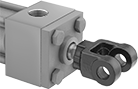
Clevis Brackets with Clevis Pin for Hydraulic Cylinders
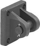
Mount a clevis bracket directly to a hydraulic cylinder using the included fasteners. Clevis brackets allow hydraulic cylinders to create a bend or pivot when connected to a pivot bracket. They include a clevis pin.
![]() For technical drawings and 3-D models, click on a part number.
For technical drawings and 3-D models, click on a part number.
Mounting Hole | |||||||||||||
|---|---|---|---|---|---|---|---|---|---|---|---|---|---|
| Pin Dia. | Wd. | Ht. | Dp. | Jaw Opening Wd. | Base Plate Thick. | Dia. | Ctr.-to-Ctr. | Mounting Fasteners Included | Material | For Cylinder Mounting Pattern | Includes | Each | |
| 1/2" | 2 1/2" | 2 1/2" | 1 5/8" | 3/4" | 3/8" | 3/8" | 1 5/8" | Yes | Steel | NFPA Heavy Duty, JIC Heavy Duty | Clevis Pin, Two Cotter Pins | 00000000 | 0000000 |
| 3/4" | 3" | 3" | 2 5/8" | 1 1/4" | 5/8" | 9/16" | 2 1/16" | Yes | Steel | NFPA Heavy Duty, JIC Heavy Duty | Clevis Pin, Two Cotter Pins | 00000000 | 000000 |
| 3/4" | 3 1/2" | 3 1/2" | 2 5/8" | 1 1/4" | 5/8" | 9/16" | 2 9/16" | Yes | Steel | NFPA Heavy Duty, JIC Heavy Duty | Clevis Pin, Two Cotter Pins | 00000000 | 000000 |
| 1" | 4 1/2" | 4 1/2" | 3 1/4" | 1 1/2" | 3/4" | 5/8" | 3 1/4" | Yes | Steel | NFPA Heavy Duty, JIC Heavy Duty | Clevis Pin, Two Cotter Pins | 00000000 | 000000 |
| 1 3/8" | 5" | 5" | 4 3/8" | 2 1/16" | 7/8" | 5/8" | 3 13/16" | Yes | Steel | NFPA Heavy Duty, JIC Heavy Duty | Clevis Pin, Two Cotter Pins | 00000000 | 000000 |
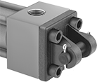
Front/Rear Flanges for Hydraulic Cylinders
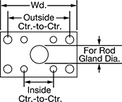
These flanges can mount on either end of the hydraulic cylinder. Use them to connect a cylinder to another part of the hydraulic system.
![]() For technical drawings and 3-D models, click on a part number.
For technical drawings and 3-D models, click on a part number.
Inside Mounting Hole | Outside Mounting Hole | |||||||||||
|---|---|---|---|---|---|---|---|---|---|---|---|---|
| Wd. | Ht. | Thick. | For Rod Gland Dia. | Dia. | Ctr.-to-Ctr. | Dia. | Ctr.-to-Ctr. | Mounting Fasteners Included | Material | For Cylinder Mounting Pattern | Each | |
| 4 1/4" | 2 1/2" | 3/8" | 7/8" | 3/8" | 1 5/8" | 7/16" | 3 7/16" | Yes | Steel | NFPA Heavy Duty, JIC Heavy Duty | 000000000 | 0000000 |
| 5 1/8" | 3" | 5/8" | 1 3/8" | 1/2" | 2 1/16" | 9/16" | 4 1/8" | Yes | Steel | NFPA Heavy Duty, JIC Heavy Duty | 000000000 | 000000 |
| 5 5/8" | 3 1/2" | 5/8" | 1 3/8" | 1/2" | 2 9/16" | 9/16" | 4 5/8" | Yes | Steel | NFPA Heavy Duty, JIC Heavy Duty | 000000000 | 000000 |
| 7 1/8" | 4 1/2" | 3/4" | 1 15/16" | 5/8" | 3 1/4" | 11/16" | 5 7/8" | Yes | Steel | NFPA Heavy Duty, JIC Heavy Duty | 000000000 | 000000 |
| 7 5/8" | 5" | 7/8" | 2 7/16" | 5/8" | 3 13/16" | 11/16" | 6 3/8" | Yes | Steel | NFPA Heavy Duty, JIC Heavy Duty | 000000000 | 000000 |
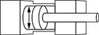
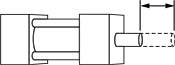
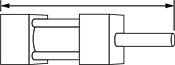
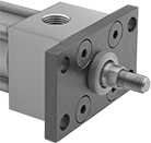
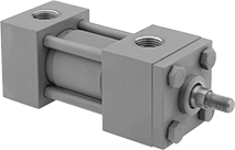
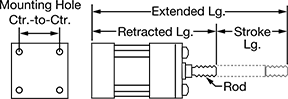
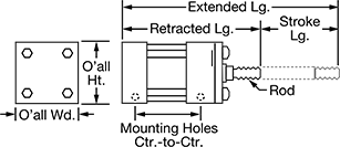
Hydraulic Cylinders
For easy interchangeability, the mounting footprint of these cylinders meets NFPA and JIC (Joint Industrial Congress) industry standards. All have two hydraulic ports: one to extend the piston rod and another to retract it. Cylinders with no cushion have a compact size. Those with an adjustable cushion reduce shock to internal components and lessen machine noise.
![]() For technical drawings and 3-D models, click on a part number.
For technical drawings and 3-D models, click on a part number.
O'all | Mounting Hole | Inlet/Outlet Connection— NPT | ||||||||||||||
|---|---|---|---|---|---|---|---|---|---|---|---|---|---|---|---|---|
| Stroke Lg. | Max. Push Force, lbs. | Max. Pull Force, lbs. | Retracted Lg. | Extended Lg. | Rod Thread Size | Wd. | Ht. | Ctr.-to-Ctr. | Thread Size | Pipe Size | Dash Size | Body Material | Max. Pressure, psi | Air Cushion Type | Each | |
NFPA and JIC Heavy Duty Mounting Pattern | ||||||||||||||||
1 1/2" Bore Dia. | ||||||||||||||||
| 1" | 4,420 | 3,650 | 7 3/8" | 8 3/8" | 7/16"-20 | 2 1/2" | 2 1/2" | 1 5/8" | 3/8"-24 | 1/2 | 08 | Steel | 2,500 | No Cushion | 000000000 | 0000000 |
| 2" | 4,420 | 3,650 | 8 3/8" | 10 3/8" | 7/16"-20 | 2 1/2" | 2 1/2" | 1 5/8" | 3/8"-24 | 1/2 | 08 | Steel | 2,500 | No Cushion | 000000000 | 000000 |
| 3" | 4,420 | 3,650 | 9 3/8" | 12 3/8" | 7/16"-20 | 2 1/2" | 2 1/2" | 1 5/8" | 3/8"-24 | 1/2 | 08 | Steel | 2,500 | No Cushion | 000000000 | 000000 |
| 4" | 4,420 | 3,650 | 10 3/8" | 14 3/4" | 7/16"-20 | 2 1/2" | 2 1/2" | 1 5/8" | 3/8"-24 | 1/2 | 08 | Steel | 2,500 | Adjustable Cushion | 000000000 | 000000 |
| 5" | 4,420 | 3,650 | 11 3/8" | 16 3/8" | 7/16"-20 | 2 1/2" | 2 1/2" | 1 5/8" | 3/8"-24 | 1/2 | 08 | Steel | 2,500 | Adjustable Cushion | 000000000 | 000000 |
2" Bore Dia. | ||||||||||||||||
| 1" | 7,850 | 5,900 | 8 1/8" | 9 1/8" | 3/4"-16 | 3" | 3" | 2 1/16" | 1/2"-20 | 1/2 | 08 | Steel | 2,500 | No Cushion | 000000000 | 000000 |
| 2" | 7,850 | 5,900 | 9 1/8" | 11 1/8" | 3/4"-16 | 3" | 3" | 2 1/16" | 1/2"-20 | 1/2 | 08 | Steel | 2,500 | No Cushion | 000000000 | 000000 |
| 3" | 7,850 | 5,900 | 10 1/8" | 13 1/8" | 3/4"-16 | 3" | 3" | 2 1/16" | 1/2"-20 | 1/2 | 08 | Steel | 2,500 | No Cushion | 000000000 | 000000 |
| 4" | 7,850 | 5,900 | 11 1/8" | 15 1/8" | 3/4"-16 | 3" | 3" | 2 1/16" | 1/2"-20 | 1/2 | 08 | Steel | 2,500 | Adjustable Cushion | 000000000 | 000000 |
| 5" | 7,850 | 5,900 | 12 1/8" | 17 1/8" | 3/4"-16 | 3" | 3" | 2 1/16" | 1/2"-20 | 1/2 | 08 | Steel | 2,500 | Adjustable Cushion | 000000000 | 000000 |
2 1/2" Bore Dia. | ||||||||||||||||
| 1" | 12,270 | 10,320 | 8 1/4" | 9 1/4" | 3/4"-16 | 3 1/2" | 3 1/2" | 2 9/16" | 1/2"-20 | 1/2 | 08 | Steel | 2,500 | No Cushion | 000000000 | 000000 |
| 2" | 12,270 | 10,320 | 9 1/4" | 11 1/4" | 3/4"-16 | 3 1/2" | 3 1/2" | 2 9/16" | 1/2"-20 | 1/2 | 08 | Steel | 2,500 | No Cushion | 000000000 | 000000 |
| 3" | 12,270 | 10,320 | 10 1/4" | 13 1/4" | 3/4"-16 | 3 1/2" | 3 1/2" | 2 9/16" | 1/2"-20 | 1/2 | 08 | Steel | 2,500 | No Cushion | 000000000 | 000000 |
| 4" | 12,270 | 10,320 | 11 1/4" | 15 1/4" | 3/4"-16 | 3 1/2" | 3 1/2" | 2 9/16" | 1/2"-20 | 1/2 | 08 | Steel | 2,500 | Adjustable Cushion | 000000000 | 000000 |
| 5" | 12,270 | 10,320 | 12 1/4" | 17 1/4" | 3/4"-16 | 3 1/2" | 3 1/2" | 2 9/16" | 1/2"-20 | 1/2 | 08 | Steel | 2,500 | Adjustable Cushion | 000000000 | 000000 |
3 1/4" Bore Dia. | ||||||||||||||||
| 1" | 20,750 | 17,020 | 9 3/4" | 10 3/4" | 1"-14 | 4 1/2" | 4 1/2" | 3 1/4" | 5/8"-18 | 3/4 | 12 | Steel | 2,500 | No Cushion | 000000000 | 000000 |
| 2" | 20,750 | 17,020 | 10 3/4" | 12 3/4" | 1"-14 | 4 1/2" | 4 1/2" | 3 1/4" | 5/8"-18 | 3/4 | 12 | Steel | 2,500 | No Cushion | 000000000 | 000000 |
| 3" | 20,750 | 17,020 | 11 3/4" | 14 3/4" | 1"-14 | 4 1/2" | 4 1/2" | 3 1/4" | 5/8"-18 | 3/4 | 12 | Steel | 2,500 | No Cushion | 000000000 | 000000 |
| 4" | 20,750 | 17,020 | 12 3/4" | 16 3/4" | 1"-14 | 4 1/2" | 4 1/2" | 3 1/4" | 5/8"-18 | 3/4 | 12 | Steel | 2,500 | Adjustable Cushion | 000000000 | 00000000 |
| 5" | 20,750 | 17,020 | 13 3/4" | 18 3/4" | 1"-14 | 4 1/2" | 4 1/2" | 3 1/4" | 5/8"-18 | 3/4 | 12 | Steel | 2,500 | Adjustable Cushion | 000000000 | 00000000 |
4" Bore Dia. | ||||||||||||||||
| 1" | 31,420 | 25,400 | 10 5/8" | 11 5/8" | 1 1/4"-12 | 5" | 5" | 3 13/16" | 5/8"-18 | 3/4 | 12 | Steel | 2,500 | No Cushion | 000000000 | 00000000 |
| 2" | 31,420 | 25,400 | 11 5/8" | 13 5/8" | 1 1/4"-12 | 5" | 5" | 3 13/16" | 5/8"-18 | 3/4 | 12 | Steel | 2,500 | No Cushion | 000000000 | 00000000 |
| 3" | 31,420 | 25,400 | 12 5/8" | 15 5/8" | 1 1/4"-12 | 5" | 5" | 3 13/16" | 5/8"-18 | 3/4 | 12 | Steel | 2,500 | No Cushion | 000000000 | 00000000 |
| 4" | 31,420 | 25,400 | 13 5/8" | 17 5/8" | 1 1/4"-12 | 5" | 5" | 3 13/16" | 5/8"-18 | 3/4 | 12 | Steel | 2,500 | Adjustable Cushion | 000000000 | 00000000 |
| 5" | 31,420 | 25,400 | 14 5/8" | 19 5/8" | 1 1/4"-12 | 5" | 5" | 3 13/16" | 5/8"-18 | 3/4 | 12 | Steel | 2,500 | Adjustable Cushion | 000000000 | 00000000 |
| For Bore Dia. | Each | |
| 1 1/2" | 00000000 | 000000 |
| 2", 2 1/2" | 00000000 | 00000 |
| 3 1/4" | 00000000 | 00000 |
| 4" | 00000000 | 00000 |
| For Bore Dia. | Mounting Fasteners Included | Each | |
| 1 1/2" | No | 00000000 | 000000 |
| 2", 2 1/2" | No | 00000000 | 00000 |
| 3 1/4" | No | 00000000 | 00000 |
| 4" | No | 00000000 | 000000 |
| For Bore Dia. | Each | |
| 1 1/2" | 00000000 | 00000 |
| 2", 2 1/2" | 00000000 | 00000 |
| 3 1/4" | 00000000 | 00000 |
| 4" | 00000000 | 00000 |