


Filter by
System of Measurement
Thread Size


Hole Shape
Insert Material

Stud Material
DFARS Specialty Metals
Export Control Classification Number (ECCN)
Handle Style
Thread Direction
Fastener Head Type
Threaded-Hole Knobs
 |
Style 26 |
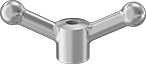
Install these knobs on a threaded stud. They provide a secure grip to position, tighten, and hold fixtures, equipment, and machinery.
Style 26—Five-Arm Grip
|
Style 26 |
Thread | Head, mm | Hub, mm | Each | |||||||
|---|---|---|---|---|---|---|---|---|---|---|
Sz. | Dp., mm | Dia. | Ht. | Dia. | Ht. | 1-9 | 10-Up | |||
Aluminum | ||||||||||
| M16 × 2 mm | 28 | 70 | 23 | 26 | 23 | 62015K512 | 000000 | 000000 | ||
Threaded Through-Hole Knobs
 |
Style 13 |
Long shafts can thread through these knobs for mounting versatility. The knobs provide a secure grip to position, tighten, and hold fixtures, equipment, and machinery.
Threaded-Hole-Mount Ball Knobs

Machine Handles
Adjustable Handles
 |  |
Style 3—Threaded Stud | Style 3—Threaded Hole |
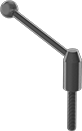
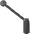
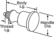
Also known as clamping handles, use these standard adjustable handles for applications involving frequent positioning, tightening, and holding adjustments. Lift the handle to rotate freely; then release the handle to engage and tighten.
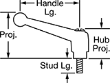
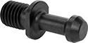
Style 3—Threaded Stud
| 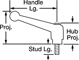 |
Threaded-stud handles mount into a threaded hole.
Powder-Coated Zinc Alloy—Powder-coated zinc alloy handles have good corrosion resistance.
303 Stainless Steel—303 stainless steel handles have excellent corrosion resistance, making them the best choice for harsh environments. They also have good chemical resistance.
Thread Size | Stud Lg., mm | Handle Lg., mm | Projection, mm | Hub Projection, mm | Stud Material | Color | Each | |||
|---|---|---|---|---|---|---|---|---|---|---|
Powder-Coated Zinc Alloy | ||||||||||
| M16 x 2 mm | 50 | 110 | 79 | 51 | Steel | Black | 6848K59 | 000000 | ||
| M16 x 2 mm | 60 | 110 | 79 | 51 | Steel | Black | 6848K61 | 00000 | ||
303 Stainless Steel | ||||||||||
| M16 x 2 mm | 50 | 110 | 79 | 51 | 303 Stainless Steel | — | 6608K38 | 00000 | ||
| M16 x 2 mm | 60 | 110 | 79 | 49 | 303 Stainless Steel | — | 6608K39 | 00000 | ||
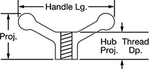
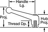
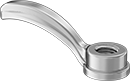
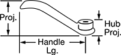
Style 3—Threaded Hole
| 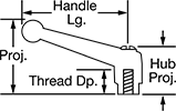 |
Threaded-hole handles install on a threaded stud.
Powder-Coated Zinc Alloy—Powder-coated zinc alloy handles have good corrosion resistance.
303 Stainless Steel—303 stainless steel handles have excellent corrosion resistance, making them the best choice for harsh environments. They also have good chemical resistance.
303 Stainless Steel Insert—303 stainless steel inserts are more corrosion resistant than black-oxide steel inserts.
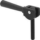
Heavy Duty Adjustable Handles
 |  |
Threaded Stud | Threaded Hole |
These rugged steel handles provide lasting durability for applications involving frequent positioning, tightening, and holding adjustments. Lift the handle to rotate freely; then release the handle to engage and tighten. These handles are also known as clamping handles. All have a black-oxide finish for mild rust resistance.
Threaded Stud
|  |
Threaded-stud handles mount into a threaded hole.
Knob | |||||||||||||
|---|---|---|---|---|---|---|---|---|---|---|---|---|---|
Thread Size | Stud Lg., mm | Handle Lg., mm | Projection, mm | Hub Projection, mm | Dia., mm | Material | Color | Stud Material | Temp. Range, ° F | Each | |||
Black-Oxide Steel | |||||||||||||
| M16 x 2 mm | 50 | 136 | 116 | 67 | 41 | Phenolic | Black | Steel | 0 to 230 | 65015K26 | 000000 | ||
Threaded Hole
|  |
Threaded-hole handles install on a threaded stud.
Thread | Knob | ||||||||||||
|---|---|---|---|---|---|---|---|---|---|---|---|---|---|
Size | Dp., mm | Handle Lg., mm | Projection, mm | Hub Projection, mm | Dia., mm | Material | Color | Insert Material | Temp. Range, ° F | Each | |||
Black-Oxide Steel | |||||||||||||
| M16 x 2 mm | 30 | 118 | 109 | 57 | 33 | Phenolic | Black | Black-Oxide Steel | 0 to 230 | 65015K13 | 000000 | ||
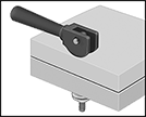
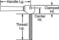
Heavy Duty Cam Handles
Threaded-Stud Mount
 |  |  |
Thread | Handle, mm | |||||||||||
|---|---|---|---|---|---|---|---|---|---|---|---|---|
Size | Lg., mm | Clamping Distance, mm | Lg. | Wd. | Ctr. Ht., mm | Clamped Ht., mm | Max. Clamping Force | Stud Material | Each | |||
Black-Oxide Steel Handle | ||||||||||||
| M16 × 2 mm | 130 | 3.57 | 137 | 32 | 22 | 45 | Not Rated | 304 Stainless Steel | 61525K33 | 000000 | ||
Sanitary Retractable Spring Plungers
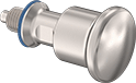 |  |
With rounded edges and polished surfaces, these spring plungers are free of nooks and crannies where dirt, water, and bacteria could collect. The seal on the base keeps contaminants off the threads and is bright blue, so you can easily spot broken pieces that fall into your line. A tug of the knob manually retracts the nose so you can do everything from positioning containers on an assembly line to locking mixing blades in place. Spring plungers are FDA compliant for direct contact with food.
316 Stainless Steel Nose—Won't corrode from frequent washdowns with harsh cleaners and detergents.
Twist-to-Lock—Free up both hands to adjust your workpiece or switch out parts without the plunger springing back and getting in the way. Pull back the handle and twist to lock the nose in its retracted position.
Spring Plungers | Replacement Seals | |||||||||||||||
|---|---|---|---|---|---|---|---|---|---|---|---|---|---|---|---|---|
Nose, mm | Nose Force, lbf | Body | Handle | Twist-to-Lock | ||||||||||||
Thread Size | Thread Lg., mm | Extended Lg. | Dia. | Extended | Compressed | Material | Lg., mm | Material | Dia., mm | Seal Material | Each | Each | ||||
316 Stainless Steel Nose | ||||||||||||||||
| M16 x 1.5 mm | 12 | 8 | 8 | 5 | 7.2 | 316 Stainless Steel | 66 | 316 Stainless Steel | 35 | Buna-N | 97158A120 | 0000000 | 97158A150 | 00000 | ||
Handle Nuts
CAT Taper Retention Knobs
 |
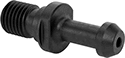
 |  |
Knob | Knob with Pilot |
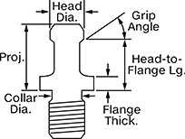
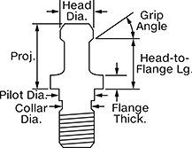
Lock tool holders in place on CNC machines with CAT taper spindles when milling, drilling, and routing. All meet industrial standards for tensile and shear strength. These knobs are also known as pull studs. To ensure compatibility with your machine, compare the features on these knobs, such as the location of O-ring seals and the pilot design, to those on your current knob. Use a torque wrench with a retention knob socket or a changeable-head torque wrench to tighten them.
Knobs with a pilot ensure precise alignment between the tool holder and spindle, reducing vibration and runout. To upgrade a standard knob to one with a pilot, confirm that the pilot diameter is small enough to fit in your tool holder without touching the inner walls where the knob seats.
Grip Angle—Grip angle is the sloped part of the knob that the machine grips to secure the tool holder. A 15˚ grip angle is sometimes referred to as a 75˚ grip angle. A 30˚ grip angle is sometimes referred to as a 60˚ grip angle.
Grip Angle | Projection | Head Dia. | Collar Dia. | Head-to-Flange Lg. | Flange Thk. | Torque Range, ft·lbf | Mfr. | Mfr. Model No. | Mfr. Equiv. Model No. | Specs. Met | JIS Specification | Each | |||
|---|---|---|---|---|---|---|---|---|---|---|---|---|---|---|---|
CAT 40 Machine Taper | |||||||||||||||
M16 × 2 mm | |||||||||||||||
| 45° | 1.266" | 0.588" | 0.49" | 0.988" | 0.236" | 45 to 55 | T.J. Davies | PS-534X45 | 350-00V, 21106, 35000V, MH40TRK | ISO 7388-3 | JIS B 6339 | 9496N22 | 000000 | ||
CAT Taper Retention Knobs with Coolant Hole
 |
 |  |
Knob | Knob with Pilot |
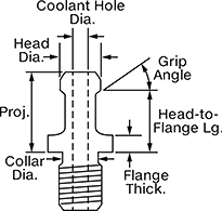
Lock tool holders in place on CNC machines with a through-spindle coolant (TSC) system. They fit machines with a CAT taper spindle. All meet industrial standards for tensile and shear strength. Also known as pull studs. Use a torque wrench with a retention knob socket or a changeable-head torque wrench to tighten them.
To ensure compatibility with your machine, compare the features on these knobs, such as the location of O-ring seals and the pilot design, to those on your current knob.
Knobs with a pilot ensure precise alignment between the tool holder and spindle, reducing vibration and runout. To upgrade a standard knob to one with a pilot, confirm that the pilot diameter is small enough to fit in your tool holder without touching the inner walls where the knob seats.
Grip Angle—Grip angle is the sloped part of the knob that the machine grips to secure the tool holder. A 15˚ grip angle is sometimes referred to as a 75˚ grip angle. A 30˚ grip angle is sometimes referred to as a 60˚ grip angle.
Grip Angle | Projection | Head Dia. | Coolant Hole Diameter | Collar Dia. | Head-to-Flange Lg. | Flange Thk. | Torque Range, ft·lbf | Mfr. | Mfr. Model No. | Mfr. Equiv. Model No. | Specs. Met | JIS Specification | Each | |||
|---|---|---|---|---|---|---|---|---|---|---|---|---|---|---|---|---|
CAT 40 Machine Taper | ||||||||||||||||
M16 × 2 mm | ||||||||||||||||
| 45° | 0.64" | 0.74" | 0.264" | 0.49" | 0.44" | 0.12" | 45 to 55 | T.J. Davies | PSC-478 | 17836, A40TRK, B40-STDH, RS4M-0105 | ASME B5.50, ISO 7388-3 | JIS B 6339 | 9499N29 | 000000 | ||
BT Taper Retention Knobs
 |  |
Knob with Pilot |
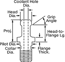
Lock tool holders in place on CNC machines with a BT taper spindle. All meet industrial standards for tensile and shear strength. These knobs are also known as pull studs. They have a pilot, which ensures precise alignment between the tool holder and spindle, reducing vibration and runout. To ensure compatibility with your machine, compare the features on these knobs, such as the pilot design, to those on your current knob. If you want to upgrade a standard knob to one with a pilot, confirm that the pilot diameter is small enough to fit in your tool holder without touching the inner walls where the knob seats.
Use a torque wrench with a retention knob socket or a changeable-head torque wrench to tighten them.
Grip Angle—Grip angle is the sloped part of the knob that the machine grips to secure the tool holder. A 15˚ grip angle is sometimes referred to as a 75˚ grip angle. A 30˚ grip angle is sometimes referred to as a 60˚ grip angle.
Grip Angle | Projection | Head Dia. | Pilot Dia. | Collar Dia. | Head-to-Flange Lg. | Flange Thk. | Torque Range, ft·lbf | Mfr. | Mfr. Model No. | Mfr. Equiv. Model No. | Specs. Met | JIS Specification | Each | |||
|---|---|---|---|---|---|---|---|---|---|---|---|---|---|---|---|---|
BT 40 Machine Taper | ||||||||||||||||
M16 × 2 mm | ||||||||||||||||
| 15° | 1.141" | 0.746" | 0.669" | 0.505" | 0.905" | 0.275" | 45 to 55 | T.J. Davies | PS-444X15 | 40PH, 329-12, 4020NTRK, 21101, 32912, B40-1500, HPS-805, PS-805, RS4M-0205 | — | JIS B 6339 | 9485N17 | 000000 | ||
| 30° | 1.378" | 0.588" | 0.669" | 0.505" | 1.1" | 0.236" | 45 to 55 | T.J. Davies | PS-444X60 | 311-13A, 4004TRK, 17808, 31113A, B40-6000, HPS-2, RB4M-0002 | — | JIS B 6339 | 9485N22 | 00000 | ||
| 45° | 0.752" | 0.74" | 0.669" | 0.505" | 0.552" | 0.236" | 45 to 55 | T.J. Davies | PS-477 | 111-26, 11126, 21105, B40-FADAL, F40TRK, RS4M-0115 | ASME B5.50, ISO 7388-3 | JIS B 6339 | 9485N18 | 00000 | ||
| 45° | 1.378" | 0.588" | 0.669" | 0.505" | 1.1" | 0.236" | 45 to 55 | T.J. Davies | PS-444X45 | 311-13, 4003TRK, 17803, 31113, B50-4500, HPS-1, P40T-1, PS-70, RB4M-0001 | — | JIS B 6339 | 9485N19 | 00000 | ||
| 45° | 1.546" | 0.592" | 0.669" | 0.505" | 1.25" | 0.187" | 45 to 55 | T.J. Davies | PS-554 | 171-26, 17126, 21116 | ASME B5.50, ISO 7388-3 | JIS B 6339 | 9485N21 | 00000 | ||
| 90° | 1.378" | 0.588" | 0.669" | 0.505" | 1.1" | 0.236" | 45 to 55 | T.J. Davies | PS-444X90 | 311-13B, 4002TRK, 17814, 31113B, B40-9000, HPS-08, POM40F, POM40MG, RB4M-0003 | — | JIS B 6339 | 9485N23 | 00000 | ||
BT Taper Retention Knobs with Coolant Hole
 |  |
Knob with Pilot |
Lock tool holders in place on CNC machines with a through-spindle coolant (TSC) system. They fit machines with a BT taper spindle. All meet industrial standards for tensile and shear strength. Also known as pull studs. These knobs have a pilot, which ensures precise alignment between the tool holder and spindle, reducing vibration and runout. To ensure compatibility with your machine, compare the features on these knobs, such as the location of O-ring seals and the pilot design, to those on your current knob. To upgrade a standard knob to one with a pilot, confirm that the pilot diameter is small enough to fit in your tool holder without touching the inner walls where the knob seats.
Use a torque wrench with a retention knob socket or a changeable-head torque wrench to tighten them.
Flange O-Ring Included—Knobs with flange O-rings block external coolant from entering your machine spindle. Match the O-ring placement and style to your current setup to ensure optimal sealing and performance.
Grip Angle—Grip angle is the sloped part of the knob that the machine grips to secure the tool holder. A 15˚ grip angle is sometimes referred to as a 75˚ grip angle. A 30˚ grip angle is sometimes referred to as a 60˚ grip angle.
Grip Angle | Projection | Head Dia. | Coolant Hole Diameter | Pilot Dia. | Collar Dia. | Head-to-Flange Lg. | Flange Thk. | Torque Range, ft·lbf | O-Rings Included | Mfr. | Mfr. Model No. | Mfr. Equiv. Model No. | Specs. Met | JIS Specification | Each | |||
|---|---|---|---|---|---|---|---|---|---|---|---|---|---|---|---|---|---|---|
BT 40 Machine Taper | ||||||||||||||||||
M16 × 2 mm | ||||||||||||||||||
| 15° | 1.136" | 0.746" | 0.264" | 0.669" | 0.505" | 0.9" | 0.157" | 45 to 55 | — | T.J. Davies | PSC-480X15 | 711-22, 21130-C, 71122, DIN40ATRK, RS4M-0114-C | ISO 7388-3 | JIS B 6339 | 9487N16 | 000000 | ||
| 15° | 1.136" | 0.746" | 0.264" | 0.669" | 0.505" | 0.9" | 0.157" | 45 to 55 | Flange O-Ring, Head O-Ring in Coolant Hole | T.J. Davies | PSCO-480X15A | B40-1500 Mori EU, HPS-366E-1 | ISO 7388-3 | JIS B 6339 | 9487N15 | 00000 | ||
| 15° | 1.141" | 0.746" | 0.264" | 0.669" | 0.505" | 0.905" | 0.275" | 45 to 55 | — | T.J. Davies | PSC-444X15 | 40PH, 329-13, 21101-C, 32913, B40-1500 H, HPS-806-1, RS4M-0205-C | ISO 7388-3 | JIS B 6339 | 9487N17 | 00000 | ||
| 30° | 1.378" | 0.588" | 0.166" | 0.669" | 0.505" | 1.1" | 0.236" | 45 to 55 | — | T.J. Davies | PSC-444X60 | 311-13E, 4004TRKC, 17820, 31113E, B40-6000 H, HPS-2 C, RB4M-0002-C | — | JIS B 6339 | 9487N22 | 00000 | ||
| 45° | 0.752" | 0.74" | 0.264" | 0.669" | 0.505" | 0.552" | 0.120" | 45 to 55 | — | T.J. Davies | PSC-479 | 312-25, 21129-C, 31225, HPS-G51, MZ40TRKC, PS-G51 | ASME B5.50, ISO 7388-3 | JIS B 6339 | 9487N18 | 00000 | ||
| 45° | 0.752" | 0.74" | 0.264" | 0.669" | 0.505" | 0.552" | 0.236" | 45 to 55 | — | T.J. Davies | PSC-477 | 111-26A, 11126A, 21105-C, B40-FADAL C, F40TRKC, RS4M-0115-C | ASME B5.50, ISO 7388-3 | JIS B 6339 | 9487N19 | 00000 | ||
| 45° | 1.378" | 0.588" | 0.166" | 0.669" | 0.505" | 1.1" | 0.236" | 45 to 55 | — | T.J. Davies | PSC-444X45 | 311-13D, 4003TRKC, 17818, 31113D, B40-4500 H, HPS-1C, RB4M-0001-C | — | JIS B 6339 | 9487N21 | 00000 | ||
| 90° | 1.378" | 0.588" | 0.166" | 0.669" | 0.505" | 1.1" | 0.236" | 45 to 55 | — | T.J. Davies | PSC-444X90 | 311-13F, 4002TRKC, 17822, 31113F, B40-9000 H, HPS-08 C, RB4M-0003-C | — | JIS B 6339 | 9487N23 | 00000 | ||
