


Filter by
Mount Type
Weight Capacity
Height
Working Orientation
Material
Application
Base Material
Power Source
Mount Movement

Mounting Location
Export Control Classification Number (ECCN)
Leg Shape

DFARS Specialty Metals
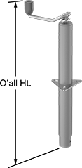
Leveling Jacks
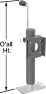 | 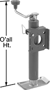 | 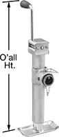 | 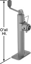 |  |
Side Handle Style A | Top Handle Style A | Side Handle Style B | Top Handle Style B | Top Handle Style D |
Mounting | ||||||||||||||||
|---|---|---|---|---|---|---|---|---|---|---|---|---|---|---|---|---|
Style | Weight Capacity | Ht. | Max. Lift | Overall Ht. | Handle Lg. | Body Material | For Hole Dia. | Fasteners Included | No. of Holes | Hole Lg. | Hole Wd. | Features | Each | |||
Weld On Side Mount with Rectangular Mounting Plate | ||||||||||||||||
Side Handle | ||||||||||||||||
| A | 1 ton/2,000 lb. | 10 7/8" to 20 7/8" | 10" | 22 3/4" | 5 7/8" | Steel | — | — | — | — | — | Foot Plate | 2963T44 | 0000000 | ||
| A | 2 1/2 ton/5,000 lb. | 10 3/8" to 20 3/8" | 10" | 22 7/8" | 6 1/2" | Steel | — | — | — | — | — | Foot Plate | 2963T48 | 00000 | ||
| A | 2 1/2 ton/5,000 lb. | 15 3/8" to 30 3/8" | 15" | 27 7/8" | 6 1/2" | Steel | — | — | — | — | — | Foot Plate | 2963T49 | 000000 | ||
Top Handle | ||||||||||||||||
| A | 2 1/2 ton/5,000 lb. | 14 1/2" to 29 1/2" | 15" | 27 1/2" | 7 5/8" | Steel | — | — | — | — | — | Foot Plate | 2963T35 | 000000 | ||
Weld On Side Mount with Square Mounting Plate | ||||||||||||||||
Side Handle | ||||||||||||||||
| A | 1 ton/2,000 lb. | 15" to 30 1/2" | 15 1/2" | 32 3/4" | 6 1/8" | Steel | — | — | — | — | — | Foot Plate | 2963T52 | 000000 | ||
Top Handle | ||||||||||||||||
| A | 1 ton/2,000 lb. | 14 3/4" to 29 3/4" | 15" | 30" | 6" | Steel | — | — | — | — | — | Foot Plate | 2963T51 | 00000 | ||
Weld On Side Mount with Tubular Mounting Plate | ||||||||||||||||
Side Handle | ||||||||||||||||
| B | 1 ton/2,000 lb. | 10 7/8" to 20 7/8" | 10" | 23" | 5 7/8" | Steel | — | — | — | — | — | Foot Plate | 2963T71 | 000000 | ||
| B | 1 ton/2,000 lb. | 15" to 30 1/2" | 15 1/2" | 32 3/4" | 6 1/8" | Steel | — | — | — | — | — | Foot Plate | 2963T53 | 000000 | ||
| B | 2 1/2 ton/5,000 lb. | 10 1/2" to 20 1/2" | 10" | 23" | 6 1/2" | Steel | — | — | — | — | — | Foot Plate | 2963T73 | 000000 | ||
| B | 2 1/2 ton/5,000 lb. | 15 1/2" to 30 1/2" | 15" | 28" | 6 1/2" | Steel | — | — | — | — | — | Foot Plate | 2963T74 | 000000 | ||
| B | 3 1/2 ton/7,000 lb. | 11" to 21" | 10" | 25 5/8" | 8 1/2" | Steel | — | — | — | — | — | Foot Plate | 2963T75 | 000000 | ||
| B | 5 ton/10,000 lb. | 17" to 29 5/8" | 12 5/8" | 39 1/2" | 13 1/2" | Steel | — | — | — | — | — | Foot Plate | 2963T81 | 000000 | ||
Top Handle | ||||||||||||||||
| B | 2 1/2 ton/5,000 lb. | 11 1/4" to 21 1/4" | 10" | 18" | 7 5/8" | Steel | — | — | — | — | — | Foot Plate | 2963T18 | 000000 | ||
Bolt On/Weld On/Through Hole with Triangular Mounting Plate | ||||||||||||||||
Top Handle | ||||||||||||||||
| D | 2 1/2 ton/5,000 lb. | 10 7/8" to 25 7/8" | 15" | 24 3/8" | 7 5/8" | Steel | 2 1/4" | No | 3 | 7/16" | 13/16" | — | 2933T35 | 000000 | ||
Sanitary Weld-On Swivel Leveling Mounts
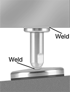 | 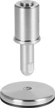 |
Shown Installed | With Cushion |
 |
With an extremely smooth finish, rounded edges, and a covered stud, these mounts are free of crevices where bacteria can grow. A silicone seal at the base of the thread cover keeps contaminants out. The seal is made with chemical additives, so you can find it with an X-ray machine if it falls into your line. To level equipment on sloped floors, insert these mounts into a hole on the bottom of your equipment, and then weld the seam to seal the connection. Once you've adjusted the stud to your desired height and angle, weld the stud to the base.
304 Stainless Steel Base—The choice for most wet locations, these mounts can withstand repeated washdowns without corroding. However, they won't hold up to cleaning solutions that contain harsh chemicals like 316 stainless steel can.
Rubber Cushion—A cushion under the base grips surfaces so vibrating equipment doesn't slide. It also protects floors from scrapes and gouges.
With Rubber Cushion | |||||||||||
|---|---|---|---|---|---|---|---|---|---|---|---|
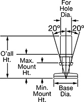
For Hole Dia., mm | Mounting Ht., mm | Swivel Range of Motion | Base Dia., mm | Food Industry Std. | Cap. per Mount, lb. | Overall Ht., mm | Cushion Material | Each | |||
304 Stainless Steel Base and Stud | |||||||||||
| 52 | 56 to 85 | 20° | 109 | FDA Compliant 21 CFR 177.2600 | 6,000 | 151 | Buna-N | 7337N12 | 0000000 | ||
| 62 | 63 to 92 | 20° | 109 | FDA Compliant 21 CFR 177.2600 | 6,000 | 151 | Buna-N | 7337N13 | 000000 | ||
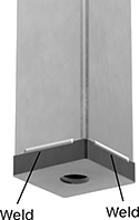
Weld-On Leveling Mount Inserts
For Square Legs
 |
For Leg | Thread | ||||||||
|---|---|---|---|---|---|---|---|---|---|
Outer Lg. | Outer Wd. | Cap. per Mount | Ht. | Size | Type | Each | |||
Steel | |||||||||
| 1" | 1" | Not Rated | 1/4" | 3/8"-16 | UNC | 8856N11 | 000000 | ||
| 1" | 1" | Not Rated | 1/4" | 1/2"-13 | UNC | 8856N14 | 00000 | ||
| 1" | 1" | Not Rated | 1/4" | 5/8"-11 | UNC | 8856N17 | 00000 | ||
| 1" | 1" | Not Rated | 1/4" | 3/4"-10 | UNC | 8856N21 | 00000 | ||
| 1 1/2" | 1 1/2" | Not Rated | 1/4" | 3/8"-16 | UNC | 8856N12 | 00000 | ||
| 1 1/2" | 1 1/2" | Not Rated | 1/4" | 1/2"-13 | UNC | 8856N15 | 00000 | ||
| 1 1/2" | 1 1/2" | Not Rated | 1/4" | 5/8"-11 | UNC | 8856N18 | 00000 | ||
| 1 1/2" | 1 1/2" | Not Rated | 1/4" | 3/4"-10 | UNC | 8856N22 | 00000 | ||
| 2" | 2" | Not Rated | 1/4" | 3/8"-16 | UNC | 8856N13 | 00000 | ||
| 2" | 2" | Not Rated | 1/4" | 1/2"-13 | UNC | 8856N16 | 00000 | ||
| 2" | 2" | Not Rated | 1/4" | 5/8"-11 | UNC | 8856N19 | 00000 | ||
| 2" | 2" | Not Rated | 1/4" | 3/4"-10 | UNC | 8856N23 | 00000 | ||
Weld-On Sights
304 Stainless Steel with Glass Window
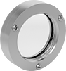 | 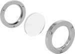 |
With Bolt-On Window | With Bolt-On Window (Unassembled) |
For Hole Dia. | OD | Window Dia. | Max. Pressure @ Temp. | Temp. Range, ° F | For Use With | Seal Material | Each | |||
|---|---|---|---|---|---|---|---|---|---|---|
With Bolt-On Window | ||||||||||
| 4 11/16" | 5" | 3 1/2" | 60 psi @ 70° F | -40 to 300 | Water, Hydraulic Fluid | Silicone Rubber | 4201K32 | 0000000 | ||
316L Stainless Steel with Glass Window
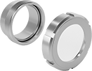 | 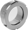 |
With Screw-Together Window (Unassembled) | With Screw-Together Window |
316L stainless steel sights are more corrosion resistant than 304 stainless steel sights.
With Screw-Together Window—Sights with a screw-together window make it easier to access your tank and clean the window than sights with a bolt-on window. To install these sights, place the body in a hole on your tank wall and weld it. Then twist on the window and tighten with a spanner wrench.
DIN 11851—DIN 11851 rated sights meet dairy fitting standards.
For Hole Dia. | OD | Window Dia. | Max. Pressure @ Temp. | Temp. Range, ° F | For Use With | Seal Material | Specs. Met | Each | |||
|---|---|---|---|---|---|---|---|---|---|---|---|
With Screw-Together Window | |||||||||||
| 2" | 3 5/8" | 2" | 150 psi @ 70° F | -20 to 390 | Water, Hydraulic Fluid, Compressed Air | Silicone Rubber | DIN 11851 | 4814K54 | 0000000 | ||
| 2 1/2" | 4 7/16" | 2 1/2" | 150 psi @ 70° F | -20 to 390 | Water, Hydraulic Fluid, Compressed Air | Silicone Rubber | DIN 11851 | 4814K55 | 000000 | ||
| 3 1/8" | 5" | 3 1/8" | 150 psi @ 70° F | -20 to 390 | Water, Hydraulic Fluid, Compressed Air | Silicone Rubber | DIN 11851 | 4814K56 | 000000 | ||
| 4" | 5 13/16" | 4" | 150 psi @ 70° F | -20 to 390 | Water, Hydraulic Fluid, Compressed Air | Silicone Rubber | DIN 11851 | 4814K57 | 000000 | ||
| 5" | 7" | 5" | 90 psi @ 70° F | -20 to 390 | Water, Hydraulic Fluid, Compressed Air | Silicone Rubber | DIN 11851 | 4814K58 | 00000000 | ||
