Filter by
Height
Light Beam Height
Sensing Distance
Electrical Connection

Component
For Use With
Certification
Sensor Type
U.S.–Mexico–Canada Agreement (USMCA) Qualifying
DFARS Specialty Metals
Export Control Classification Number (ECCN)
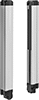
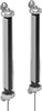
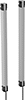
Light Curtains
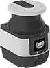
Other Products