


Base Type Base Type |
|---|
|
For Mounting Stem Diameter For Mounting Stem Diameter |
|---|
|
|
Base Magnetic Pull Base Magnetic Pull |
|---|
|
|
|
Base Length Base Length |
|---|
|
|
|
Base Height Base Height |
|---|
|
|
|
DFARS (Defense Acquisition Regulations Supplement) DFARS (Defense AcquisitionRegulations Supplement) |
|---|
Base Material Base Material |
|---|
|
|
RoHS (Restriction of Hazardous Substances) RoHS (Restriction ofHazardous Substances) |
|---|
|
REACH (Registration, Evaluation, Authorization and Restriction of Chemicals) REACH (Registration,Evaluation, Authorization and Restriction of Chemicals) |
|---|
|
Selecting Clamps Using Pipe, Conduit, or Tubing Trade Size
More
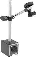
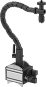
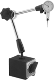
Jointed-Arm Magnetic-Base Indicator Holders
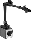
Position the arm by adjusting joints at the top, middle, and bottom. The magnetic base has a V-grooved bottom for mounting on curved and flat metal surfaces and a magnetic-release switch for easy setups. Holders have fine-adjustment knobs for precise positioning.
Indicator Holders | |||||||||||||||||
|---|---|---|---|---|---|---|---|---|---|---|---|---|---|---|---|---|---|
Base | Arm | Replacement Arms | Replacement Clamps | ||||||||||||||
| For Mounting Stem Dia. | Lg. | Wd. | Ht. | Thread Size | Thread Pitch, mm | Material | Magnetic Pull, lbs. | Lg. | Dia. | Features | Includes | Each | Each | Each | |||
Dovetail and Stem Mount | |||||||||||||||||
| 6mm, 8mm, 3/8" | 1 1/2" | 1 1/4" | 1 3/8" | M5 | 0.8 | Cast Iron | 70 | 4 1/4" | 3/8" | Fine-Adjustment Base, Fine-Adjustment Clamp, Magnetic-Release Switch | Swivel Clamp | 00000000 | 0000000 | 00000000 | 000000 | 00000000 | 000000 |
| 6mm, 8mm, 3/8" | 2 3/8" | 1 15/16" | 2 5/32" | M8 | 1.25 | Cast Iron | 176 | 11" | 1/2" | Fine-Adjustment Base, Fine-Adjustment Clamp, Magnetic-Release Switch | Swivel Clamp | 00000000 | 000000 | 00000000 | 00000 | 00000000 | 00000 |
| 6mm, 8mm, 3/8" | 4 3/4" | 1 15/16" | 2 5/32" | M10 | 1.25 | Cast Iron | 290 | 20" | 3/4" | Fine-Adjustment Clamp, Magnetic-Release Switch | Swivel Clamp | 00000000 | 000000 | 00000000 | 000000 | 00000000 | 00000 |
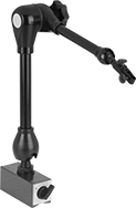
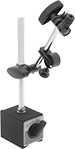
Economy Jointed-Arm Magnetic-Base Indicator Holders
Position the arm by adjusting joints at the top, middle, and bottom. The magnetic base has a V-grooved bottom for mounting on curved and flat metal surfaces and a magnetic-release switch for easy setups. Use the fine adjustment knob on the clamp for precise positioning.
Base | Arm | |||||||||||
|---|---|---|---|---|---|---|---|---|---|---|---|---|
| For Mounting Stem Dia. | Lg. | Wd. | Ht. | Thread Size | Thread Pitch, mm | Material | Magnetic Pull, lbs. | Lg. | Dia. | Features | Each | |
Dovetail and Stem Mount | ||||||||||||
| 3/8" | 2 1/2" | 2" | 2 3/16" | M8 | 1.25 | Cast Iron | 132 | 13 1/2" | 0.464" | Fine-Adjustment Clamp, Magnetic-Release Switch | 000000 | 000000 |
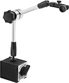
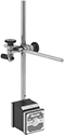
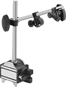
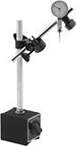
Rigid-Arm Magnetic-Base Indicator Holders
The magnetic base has a V-grooved bottom for mounting on flat and curved metal surfaces and a magnetic release switch for easy setups.
Holders with fine-adjustment arm give you more precise control over the arm position.
![]() For technical drawings and 3-D models, click on a part number.
For technical drawings and 3-D models, click on a part number.
Base | Upright Post | Arm | ||||||||||||||
|---|---|---|---|---|---|---|---|---|---|---|---|---|---|---|---|---|
| For Mounting Lug Hole Dia. | For Mounting Stem Dia. | Lg. | Wd. | Ht. | Thread Size | Thread Pitch, mm | Material | Magnetic Pull, lbs. | Dia. | Ht. | Material | Lg. | Dia. | Features | Each | |
Lug and Stem Mount | ||||||||||||||||
| 1/4" | 5/32"-1/4" | 2.559" | 1.97" | 2.165" | M8 | 1.25 | Cast Iron | 176 | 7/16" | 6 7/8" | Steel | 6 1/2" | 0.375" | Fine-Adjustment Arm, Magnetic-Release Switch | 0000000 | 000000 |
| 1/4" | 5/32"-1/4" | 2.559" | 1.97" | 2.165" | M8 | 1.25 | Cast Iron | 176 | 7/16" | 6 7/8" | Steel | 6 1/2" | 0.375" | Magnetic-Release Switch | 000000 | 00000 |
| 1/4" | 1/4"-5/16" | 2.953" | 1.97" | 2.165" | M8 | 1.25 | Cast Iron | 220 | 5/8" | 8 7/8" | Steel | 6 1/2" | 0.563" | Fine-Adjustment Arm, Magnetic-Release Switch | 0000000 | 00000 |
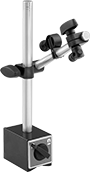
Economy Rigid-Arm Magnetic-Base Indicator Holders
The magnetic base has a V-grooved bottom for mounting on flat and curved metal surfaces and a magnetic release switch for easy setups. Use the fine-adjustment knob for precise positioning of the arm.
Base | Upright Post | Arm | ||||||||||||||
|---|---|---|---|---|---|---|---|---|---|---|---|---|---|---|---|---|
| For Mounting Lug Hole Dia. | For Mounting Stem Dia. | Lg. | Wd. | Ht. | Thread Size | Thread Pitch, mm | Material | Magnetic Pull, lbs. | Dia. | Ht. | Material | Lg. | Dia. | Features | Each | |
Lug and Stem Mount | ||||||||||||||||
| 1/4" | 3/8" | 2 5/8" | 2" | 2 15/16" | M8 | 1.25 | Cast Iron | 132 | 7/16" | 6.9" | Steel | 5 13/16" | 0.464" | Fine-Adjustment Arm, Magnetic-Release Switch | 0000000 | 000000 |
Starrett Rigid-Arm Magnetic-Base Indicator Holders
The magnetic base has a flat bottom for mounting on flat metal surfaces and a magnetic release switch for easy setups.
Fine-adjustment attachment (sold separately) can be installed between the upright post and the base to give you more precise control over positioning.
Base | Upright Post | Arm | |||||||||||||
|---|---|---|---|---|---|---|---|---|---|---|---|---|---|---|---|
| For Mounting Lug Hole Dia. | For Mounting Stem Dia. | Lg. | Wd. | Ht. | Thread Size | Material | Magnetic Pull, lbs. | Dia. | Ht. | Lg. | Dia. | Features | Manufacturer Model Number | Each | |
Lug and Stem Mount | |||||||||||||||
| 1/4" | 1/4" | 1 57/64" | 1 5/8" | 1 29/32" | 1/4"-20 | Steel | 75 | 3/8" | 7 5/16" | 6" | 0.25" | Magnetic-Release Switch | 657AA | 00000000 | 0000000 |
| Fine Adjustment Attachment | 00000000 | Each | 000000 |
Fine Adjustment Attachments for Starrett Magnetic-Base Indicator Holders
Install this attachment onto Starrett magnetic-base holders for more precise control over positioning.
| For Arm Dia. | Material | Manufacturer Model Number | Each | |
| 0.5" | Steel | 657W | 00000000 | 000000 |
Flexible-Arm Magnetic-Base Indicator Holders
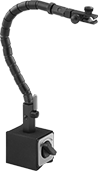
and Fine-Adjustment
Clamp
Adjust the flexible arm to nearly any position. These holders have a ball-and-socket segmented arm that locks in place with a lever. The magnetic base has a release switch for easy setups.
Holders with V-grooved base can be mounted on both curved and flat surfaces.
Holders with fine-adjustment base or clamp give you more precise control over positioning.
Indicator Holders | |||||||||||||||
|---|---|---|---|---|---|---|---|---|---|---|---|---|---|---|---|
Base | Arm | Replacement Arms | |||||||||||||
| For Mounting Stem Dia. | Type | Lg. | Wd. | Ht. | Thread Size | Thread Pitch, mm | Material | Magnetic Pull, lbs. | Lg. | Dia. | Features | Each | Each | ||
Dovetail and Stem Mount | |||||||||||||||
| 3/8" | V-Grooved | 2" | 2 1/2" | 2 5/8" | 5/16''-18 | __ | Steel | 90 | 15 1/4" | 0.625" | Fine-Adjustment Clamp, Magnetic-Release Switch | 00000000 | 0000000 | 00000000 | 000000 |
Stem Mount | |||||||||||||||
| 1/8"-1/2" | Flat | 2" | 1 5/8" | 2" | __ | __ | Steel | 65 | 14" | 0.625" | Fine-Adjustment Base, Magnetic-Release Switch | 00000000 | 000000 | 00000000 | 000000 |
| 5/32"-1/2" | V-Grooved | 2 1/2" | 2" | 2 1/4" | M8 | 1.25 | Steel | 180 | 12 1/2" | 0.63" | Magnetic-Release Switch | 0000000 | 00000 | 0000000 | 00000 |
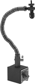
Rigid-Arm Magnetic-Base Indicator Holders for Uneven Surfaces
The base is comprised of adjustable magnetic pins which allow it to conform to any shape and grip most metal surfaces. Use the fine-adjustment knob to precisely position the arm.
Base | Upright Post | Arm | |||||||||||||||
|---|---|---|---|---|---|---|---|---|---|---|---|---|---|---|---|---|---|
| For Mounting Lug Hole Dia. | For Mounting Stem Dia. | Lg. | Wd. | Ht. | Thread Size | Thread Pitch, mm | Material | Magnetic Pull, lbs. | Dia. | Ht. | Material | Lg. | Dia. | Material | Features | Each | |
Lug and Stem Mount | |||||||||||||||||
| 1/4" | 5/32"-3/8" | 1 15/16" | 1 5/8" | 2 7/8" | M8 | 1.25 | Cast Aluminum | 120 | 15/32" | 7 1/16" | Steel | 3 1/2" | 0.469" | Steel | Fine-Adjustment Arm, Magnetic-Release Switch | 0000000 | 0000000 |
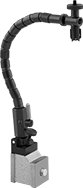
Flexible-Arm Magnetic-Base Indicator Holders for Uneven Surfaces
A flexible ball-and-socket segmented arm adjusts to nearly any position and locks in place with a lever. The base is comprised of adjustable magnetic pins which allow it to conform to any shape and grip most metal surfaces. It has a magnetic-release switch for easy setups.
Base | Arm | ||||||||||||
|---|---|---|---|---|---|---|---|---|---|---|---|---|---|
| For Mounting Stem Dia. | Lg. | Wd. | Ht. | Thread Size | Thread Pitch, mm | Material | Magnetic Pull, lbs. | Lg. | Dia. | Material | Features | Each | |
Stem Mount | |||||||||||||
| 5/64"-1/2" | 1 15/16" | 1 5/8" | 2 7/8" | M8 | 1.25 | Cast Aluminum | 120 | 12 1/2" | 0.47" | Steel | Magnetic-Release Switch | 0000000 | 0000000 |
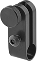
Low-Profile Magnetic Base Holders with Positioning Arm
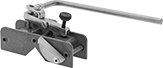
Use a swivel clamp (not included) to attach an indicator to the positioning arm. These holders are often used in areas with limited space. They have a magnetic base with a V-grooved bottom for mounting on curved and flat metal surfaces and a magnetic-release switch for easy setups.
Style A has a fine-adjustment knob on the arm for precise positioning.
Style B has a pivoting arm attached to an adjustable sliding block. Use the fine-adjustment knob on the sliding block for precise positioning. The arm can be removed to hold a 1/4” lug back.
Base | Arm | ||||||||||||
|---|---|---|---|---|---|---|---|---|---|---|---|---|---|
| Style | Type | Lg. | Wd. | Ht. | Material | Magnetic Pull, lbs. | Dia. | Flexibility | Lg. | Material | Features | Each | |
| A | V-Grooved | 3 1/2" | 1 1/8" | 1" | Stainless Steel | 50 | 0.25" | Rigid | 6" | Steel | Fine-Adjustment Arm, Magnetic-Release Switch | 000000 | 000000 |
| B | V-Grooved | 3 1/2" | 1 1/8" | 1 1/2" | Stainless Steel | 50 | 0.25" | Rigid | 6" | Steel | Fine-Adjustment Arm, Magnetic-Release Switch | 000000 | 000000 |
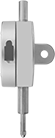
Low-Profile Magnetic-Base Indicator Holders with Multiple Mounting Locations
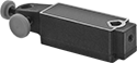
For more versatility than other low-profile holders, this holder has six locations for mounting indicators and accessories, including two mounting holes and four places to mount an indicator lug back with the included thumb screws. Use it in areas with limited space. The magnetic base has a V-grooved bottom for mounting on curved and flat metal surfaces.
![]() For technical drawings and 3-D models, click on a part number.
For technical drawings and 3-D models, click on a part number.
For Stem Dia. Mounting Hole | Base | |||||||
|---|---|---|---|---|---|---|---|---|
| Unthreaded Round | Unthreaded V-Shape | Type | Ht. | Material | Magnetic Pull, lbs. | Mount Type | Each | |
| 3/8" | 1/8"-5/16" | Flat | 1 1/16" | Zinc | 45 | Stem | 00000000 | 000000 |
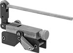
Low-Profile Magnetic-Base Indicator Holders
Use this holder in areas with limited space. It has a nut and bolt for holding a 1/4” lug-back indicator. The magnetic base has a V-grooved bottom for mounting on curved and flat metal surfaces and a magnetic-release switch for easy setups.
Base | |||||||||
|---|---|---|---|---|---|---|---|---|---|
| For Mounting Lug Hole Dia. | Lg. | Wd. | Ht. | Material | Magnetic Pull, lbs. | Thread Size | Features | Each | |
Lug Mount | |||||||||
| 1/4" | 3 1/2" | 1 1/8" | 1" | Steel | 50 | 8-32 | Magnetic-Release Switch | 000000 | 000000 |
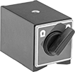
Magnetic Bases
Use the threaded mounting hole on these bases to hold upright posts and fixtures. Bases have a magnetic-release switch for easy setups.
V-grooved bases can be mounted on both curved and flat metal surfaces.
Base | ||||||||||
|---|---|---|---|---|---|---|---|---|---|---|
| Lg. | Wd. | Ht. | Thread Size | Thread Pitch, mm | Material | Magnetic Pull, lbs. | Mounting Hole Location | Features | Each | |
Flat | ||||||||||
| 1 3/16" | 1 3/16" | 1 3/16" | M5 | 0.8 | Cast Iron | 38 | Top | Magnetic-Release Switch | 0000000 | 000000 |
| 4 3/4" | 2 3/8" | 2 1/16" | M8 | 1.25 | Cast Iron | 337 | Top | Magnetic-Release Switch | 000000 | 000000 |
V-Grooved | ||||||||||
| 2 5/8" | 2" | 2 3/16" | M8 | 1.25 | Cast Iron | 176 | Top | Magnetic-Release Switch | 000000 | 00000 |
| 3" | 2" | 2 3/16" | M8 | 1.25 | Cast Iron | 220 | Top | Magnetic-Release Switch | 0000000 | 00000 |
| 4 5/8" | 2" | 2 3/16" | M10 | 1.5 | Cast Iron | 292 | Top | Magnetic-Release Switch | 0000000 | 000000 |
Economy Magnetic Bases
This magnetic base has a threaded mounting hole to hold upright posts and fixtures. It has a V-grooved bottom for mounting on curved and flat metal surfaces and a magnetic-release switch for easy setups.

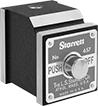
Starrett Magnetic Bases
The threaded mounting holes on this base hold upright posts and fixtures. It has a flat bottom for mounting on flat metal surfaces and a V-step at the top of the base for mounting on round surfaces. The magnetic-release switch allows for easy setups.
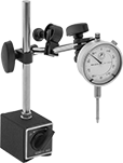
Mitutoyo Dial Plunger-Style Variance Indicators with Magnetic-Base Holder
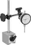
The magnetic base has a V-grooved bottom to provide a solid mount on flat and curved metal surfaces. It also has a magnetic release switch for easy setups.
Indicator has a continuous dial numbered clockwise around the face for direct measurements. A spring-loaded plunger retracts and extends to measure objects. Rotate the dial face for viewing at multiple angles.
Dial | Contact Point | Upright Post | Arm | |||||||||||||||
|---|---|---|---|---|---|---|---|---|---|---|---|---|---|---|---|---|---|---|
| Measuring Range | Measuring Increments | Accuracy | Industry Designation | Indicator Mount. Stem Dia. | Mount. Lug Hole Dia. | Dia. | Reading | Head Dia. | Lg. | Mount. Thread Size | Base Magnetic Pull, lbs. | Dia. | Ht. | Lg. | Flexibility | Mfr. Model No. | Each | |
Lug and Stem Mount | ||||||||||||||||||
| 0"-1" | 0.001" | ±0.002" | AGD Group 2 | 3/8" | 1/4" | 2 1/4" | 0-100 | 0.118" | 1.366" | 4-48 | 135 | 1/2" | 7" | 6 1/2" | Rigid | 646PKA079B | 000000 | 0000000 |
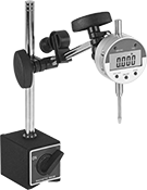
Economy Dial Plunger-Style Variance Indicators with Magnetic-Base Holder
Place the magnetic base on metal surfaces for a solid mount. The base has a V-grooved bottom for mounting on flat and curved surfaces and magnetic release switch for easy setups. Use the fine-adjustment knob for precise positioning of the holder’s arm.
Indicator has a continuous dial numbered clockwise around the face for direct measurements. A spring-loaded plunger retracts and extends to measure objects. Rotate the dial face for viewing at multiple angles.
Dial | Contact Point | Upright Post | Arm | ||||||||||||||
|---|---|---|---|---|---|---|---|---|---|---|---|---|---|---|---|---|---|
| Measuring Range | Measuring Increments | Accuracy | Industry Designation | Indicator Mount. Stem Dia. | Mount. Lug Hole Dia. | Dia. | Reading | Head Dia. | Lg. | Mount. Thread Size | Base Magnetic Pull, lbs. | Dia. | Ht. | Lg. | Flexibility | Each | |
Lug and Stem Mount | |||||||||||||||||
| 0"-1" | 0.001" | ±0.001" | AGD Group 2 | 3/8" | 1/4" | 2 3/8" | 0-100 | 0.1" | 1/4" | 4-48 | 132 | 7/16" | 7" | 5 13/16" | Rigid | 00000000 | 000000 |
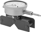
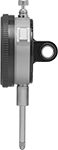
Dial Plunger-Style Variance Indicators with Magnetic-Base Holder
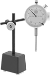
For a solid mount on metal surfaces, this indicator comes with a magnetic base. It has a continuous dial numbered clockwise around the face for direct measurements. A spring-loaded plunger retracts and extends to measure objects.
Dial | Contact Point | Upright Post | Arm | ||||||||||||||
|---|---|---|---|---|---|---|---|---|---|---|---|---|---|---|---|---|---|
| Measuring Range | Measuring Increments | Accuracy | Industry Designation | Indicator Mount. Stem Dia. | Mount. Lug Hole Dia. | Dia. | Reading | Head Dia. | Lg. | Mount. Thread Size | Base Magnetic Pull, lbs. | Dia. | Ht. | Lg. | Flexibility | Each | |
Lug and Stem Mount | |||||||||||||||||
| 0"-1" | 0.001" | ±0.002" | AGD Group 2 | 3/8" | 1/4" | 2 1/4" | 0-100 | 1/4" | 1/4" | 4-48 | 45 | 5/16" | 4" | 4 1/2" | Rigid | 0000000 | 0000000 |
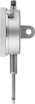
Economy Electronic Plunger-Style Variance Indicators with Magnetic-Base Holder
A magnetic base provides a solid mount on metal surfaces. It has a V-grooved bottom for mounting on flat and curved surfaces and a magnetic release switch for easy setups. Use the fine-adjustment knob for precise positioning of the holder’s arm.
The indicator has a spring-loaded plunger that retracts and extends to measure objects. It has zero-position memory, also known as absolute (ABS) positioning, which retains the measuring position when the indicator is off. A zero-set button lets you start measuring at any point, and a go/no-go operation indicates when measurements fall outside your set tolerance.
Measuring Range | Measuring Increments | Accuracy | Contact Point | Base | |||||||||||||||
|---|---|---|---|---|---|---|---|---|---|---|---|---|---|---|---|---|---|---|---|
| Inch | Metric, mm | Inch | Metric, mm | Inch | Metric, mm | Industry Designation | Mount. Stem Dia. | Mount. Lug Hole Dia. | Head Dia. | Lg. | Mount. Thread Size | Lg. | Wd. | Magnetic Pull, lbs. | Arm Flexibility | Batteries Included | SPC Data Output | Each | |
Lug and Stem Mount | |||||||||||||||||||
| 0"-1" | 0-25 | 0.0005" | 0.01 | ±0.001" | ±0.03 | AGD Group 2 | 3/8" | 1/4" | 0.2" | 0.3" | 4-48 | 2 11/32" | 1 13/16" | 85 | Rigid | Yes | No | 0000000 | 0000000 |
| Replacement Battery (1 per Pkg.) | 0000000 | Pkg. | 00000 |
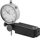
Economy Dial Lever-Style Variance Indicators with Rigid-Arm Magnetic-Base Holder
Place the magnetic base on metal surfaces for a solid mount. It has a V-grooved bottom for mounting on flat and curved surfaces and a magnetic release switch for easy setups. Use the fine-adjustment knob for precise positioning of the holder’s arm.
Also known as a test indicator, the indicator has a lever-style contact point that pivots as it comes into contact with a surface and a balanced dial with positive values on one side and negative values on the other side. It has jeweled bearings for high sensitivity, wear resistance, and a long service life. Rotate the dial face for viewing at multiple angles.
Dial | Contact Point | Base | Upright Post | ||||||||||||
|---|---|---|---|---|---|---|---|---|---|---|---|---|---|---|---|
| Measuring Range | Measuring Increments | Accuracy | Reading | Dia. | Head Dia. | Lg. | Swivel Angle | Lg. | Wd. | Magnetic Pull, lbs. | Dia. | Ht. | Includes | Each | |
Horizontal Orientation | |||||||||||||||
| 0"-0.03" | 0.0005" | ±0.0004" | 0-15-0 | 1 9/32" | 0.078" | 1/2" | 180° | 2 1/2" | 2" | 132 | 7/16" | 6.9" | 5/32" Dia. Dovetail-to-Stem Attachment 3/8" Dia. Dovetail-to-Stem Attachment | 0000000 | 000000 |
Economy Dial Lever-Style Variance Indicators with Jointed-Arm Magnetic-Base Holder
Position the arm by adjusting joints at the top, middle, and bottom. The magnetic base has a V-grooved bottom for mounting on flat and curved metal surfaces and a magnetic release switch for easy setups. Use the fine-adjustment knob on the holder’s clamp for precise positioning of the indicator.
Also known as a test indicator, the indicator has a lever-style contact point that pivots as it comes into contact with a surface and a balanced dial with positive values on one side and negative values on the other side. It has jeweled bearings for high sensitivity, wear resistance, and a long service life. Rotate the dial face for viewing at multiple angles.
Dial | Contact Point | Base | |||||||||||
|---|---|---|---|---|---|---|---|---|---|---|---|---|---|
| Measuring Range | Measuring Increments | Accuracy | Reading | Dia. | Head Dia. | Lg. | Swivel Angle | Lg. | Wd. | Magnetic Pull, lbs. | Includes | Each | |
Horizontal Orientation | |||||||||||||
| 0"-0.03" | 0.0005" | ±0.0004" | 0-15-0 | 1 9/32" | 0.078" | 1/2" | 180° | 2 1/2" | 2" | 132 | 5/32" Dia. Dovetail-to-Stem Attachment 3/8" Dia. Dovetail-to-Stem Attachment | 0000000 | 000000 |
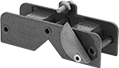
Magnetic Vibration-Damping Routing Clamps
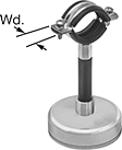
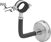
Temporarily route material across duct, racks, machinery, and other ferrous surfaces. Clamps fit tightly around pressurized lines in hydraulic systems to lessen vibration. Rubber cushions reduce wear from clamp edges and protect lines from corrosion caused by metal-to-metal contact. All clamps are zinc-plated steel for good corrosion resistance.
![]() For technical drawings and 3-D models, click on a part number.
For technical drawings and 3-D models, click on a part number.
ID | ||||||||||||
|---|---|---|---|---|---|---|---|---|---|---|---|---|
| Inch | Metric, mm | Cushion Color | Capacity, lbs. | Lg. | Wd. | Ht. | Magnet Dia. | Clamping Fasteners Included | Temp. Range, °F | For Use Outdoors | Each | |
Zinc-Plated Steel | ||||||||||||
Straight | ||||||||||||
| 9/16"-3/4" | 14-19 | Black | 75 | 2 1/2" | 13/16" | 2 3/8" | 2 1/2" | Yes | 0° to 245° | Yes | 0000000 | 000000 |
| 9/16"-3/4" | 14-19 | Black | 75 | 2 1/2" | 13/16" | 5 1/8" | 2 1/2" | Yes | 0° to 245° | Yes | 0000000 | 00000 |
| 9/16"-3/4" | 14-19 | Black | 130 | 2 1/2" | 13/16" | 2 3/4" | 3 1/8" | Yes | 0° to 245° | Yes | 0000000 | 00000 |
| 13/16"-1" | 21-25 | Black | 75 | 2 5/8" | 13/16" | 2 9/16" | 2 1/2" | Yes | 0° to 245° | Yes | 0000000 | 00000 |
| 13/16"-1" | 21-25 | Black | 75 | 2 5/8" | 13/16" | 5 11/16" | 2 1/2" | Yes | 0° to 245° | Yes | 0000000 | 00000 |
| 13/16"-1" | 21-25 | Black | 130 | 2 5/8" | 13/16" | 2 15/16" | 3 1/8" | Yes | 0° to 245° | Yes | 0000000 | 00000 |
| 1"-1 1/4" | 25-32 | Black | 75 | 2 3/4" | 13/16" | 2 3/4" | 2 1/2" | Yes | 0° to 245° | Yes | 0000000 | 00000 |
| 1"-1 1/4" | 25-32 | Black | 130 | 2 3/4" | 13/16" | 3 1/8" | 3 1/8" | Yes | 0° to 245° | Yes | 0000000 | 00000 |
| 1"-1 1/4" | 25-32 | Black | 130 | 2 3/4" | 13/16" | 5 7/8" | 3 1/8" | Yes | 0° to 245° | Yes | 0000000 | 00000 |
| 1 1/4"-1 7/16" | 32-37 | Black | 75 | 3" | 13/16" | 2 15/16" | 2 1/2" | Yes | 0° to 245° | Yes | 0000000 | 00000 |
| 1 1/4"-1 7/16" | 32-37 | Black | 130 | 3" | 13/16" | 3 3/8" | 3 1/8" | Yes | 0° to 245° | Yes | 0000000 | 00000 |
| 1 1/4"-1 7/16" | 32-37 | Black | 130 | 3" | 13/16" | 6 5/16" | 3 1/8" | Yes | 0° to 245° | Yes | 0000000 | 00000 |
90° Angle | ||||||||||||
| 9/16"-3/4" | 14-19 | Black | 75 | 6 1/2" | 13/16" | 5 11/16" | 2 1/2" | Yes | 0° to 245° | Yes | 0000000 | 00000 |
| 13/16"-1" | 21-25 | Black | 75 | 6 11/16" | 13/16" | 5 7/8" | 2 1/2" | Yes | 0° to 245° | Yes | 0000000 | 00000 |
| 1"-1 1/4" | 25-32 | Black | 130 | 8 1/16" | 13/16" | 6 1/2" | 3 1/8" | Yes | 0° to 245° | Yes | 0000000 | 00000 |
| 1 1/4"-1 7/16" | 32-37 | Black | 130 | 8 1/4" | 13/16" | 6 7/8" | 3 1/8" | Yes | 0° to 245° | Yes | 0000000 | 00000 |
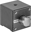
Magnetic Routing Ring Bases
Temporarily mount routing rings and other threaded components to steel and iron surfaces.
![]() For technical drawings and 3-D models, click on a part number.
For technical drawings and 3-D models, click on a part number.
Routing Rings
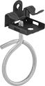
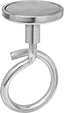
Also known as bridle rings, routing rings have an open-eye design that allows you to quickly install wire and cable. Press-fit routing rings mount onto beams and other flat surfaces. A hole on the back of the jaw allows you to orient the ring horizontally. Lightly hammer to install. Magnetic routing rings provide a temporary hold on steel and iron surfaces.
![]() For technical drawings and 3-D models, click on a part number.
For technical drawings and 3-D models, click on a part number.
Eye Diameter | Overall | ||||||||||
|---|---|---|---|---|---|---|---|---|---|---|---|
| Inch | Metric, mm | For Beam Thickness | Material | Temp. Range, °F | Cap., lbs. | Lg. | Wd. | Ht. | Pkg. Qty. | Pkg. | |
Press Fit | |||||||||||
| 2" | 51 | 1/8"-1/4" | Galvanized Steel | __ | 15 | 2 7/16" | 1 5/16" | 3 1/2" | 1 | 0000000 | 00000 |
| 2" | 51 | 5/16"-1/2" | Galvanized Steel | __ | 15 | 2 7/16" | 1 5/16" | 3 1/2" | 1 | 0000000 | 0000 |
| 2" | 51 | 9/16"-3/4" | Galvanized Steel | __ | 15 | 2 7/16" | 1 7/16" | 3 1/2" | 1 | 0000000 | 00000 |
| Each | |||||||||||
Magnetic | |||||||||||
| 3/4" | 19 | __ | Zinc-Plated Steel | -40° to 176° | 40 | 1" | 1 1/8" | 2" | __ | 0000000 | 0000 |
| 1 1/4" | 32 | __ | Zinc-Plated Steel | -40° to 570° | 90 | 1 5/8" | 1 1/2" | 3 1/4" | __ | 0000000 | 0000 |
| 2" | 51 | __ | Zinc-Plated Steel | -40° to 570° | 90 | 2 3/8" | 1 1/2" | 4 7/8" | __ | 0000000 | 0000 |