Filter by
Component
Shape
System of Measurement
For Use With
Outlet Regulation
Fitting Connection


Pressure Adjustment

Inlet Connection
Manufacturer Series
DFARS Specialty Metals


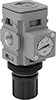
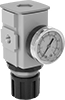
About Air Preparation
Customize your air preparation system with dryers, filters, and other purifying parts.
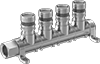
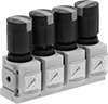
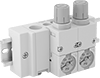
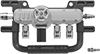
Compressed Air Regulator Manifolds
Other Products