


Filter by
Width


Return Type

Overall Width
Control Signal
Export Control Classification Number (ECCN)
DFARS Specialty Metals
Height
Overall Height
Proportional HVAC Duct Damper Actuators
 |
This actuator provides better control than incremental actuators because it is constantly being positioned in response to duct airflow requirements. Use to automatically adjust dampers to regulate airflow. It attaches to the damper shaft to rotate it open and closed when signaled by a controller (not included). Actuator can be set to return the damper to an open or closed position if the power fails. Use the crank for precise adjustments.
For Max. Damper Shaft | Overall | ||||||||||||||||
|---|---|---|---|---|---|---|---|---|---|---|---|---|---|---|---|---|---|
Torque, in·lbf | Voltage | Current, amp | Control Signal | Electrical Connection Type | Dia. | Ht. | Wd. | Material | Direction of Operation | Rotation Range | Ht. | Wd. | Dp. | Each | |||
With Spring Return | |||||||||||||||||
| 177 | 24V AC/24V DC | 0.7 | 0V DC to 10V DC/0 mA to 20 mA | Hardwire | 3/4" | 1/2" | 1/2" | Aluminum | Clockwise, Counterclockwise | 30° to 90° | 10 3/8" | 4" | 3 1/4" | 1742K82 | 0000000 | ||
Airflow Dampers
 |
Standard Airflow Damper, Female × Male |
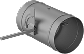 |
Gasketed Airflow Damper |
The simplest, most reliable way to regulate airflow in standard duct. Turn the lever to adjust the blade.
Gasketed Airflow Damper—The blade has a rubber gasket to prevent leaks better than other dampers.
Galvanized Steel—Strong and corrosion resistant, galvanized steel is the most commonly used ductwork material.
Lightweight Aluminum—One-third the weight of steel, aluminum duct is easier to handle during installation. It resists rust in wet environments but won’t last as long as steel.
Galvanized Steel | Lightweight Aluminum | ||||||||||
|---|---|---|---|---|---|---|---|---|---|---|---|
Duct Size | ID | OD | Overall Lg. | Ga. | Gasket Material | Each | Each | ||||
Standard Airflow Damper | |||||||||||
Female × Male | |||||||||||
| 3 | 3" | 2 7/8" | 5 3/8" | 20 | — | ——— | 0 | 1773K41 | 000000 | ||
| 6 | 6" | 5 7/8" | 5 3/8" | 20 | — | ——— | 0 | 1773K44 | 00000 | ||
Gasketed Airflow Damper | |||||||||||
Male | |||||||||||
| 4 | — | 3 7/8" | 10" | 20 | Neoprene | 2041K31 | 0000000 | ——— | 0 | ||
| 6 | — | 5 7/8" | 10" | 20 | Neoprene | 2041K32 | 000000 | ——— | 0 | ||
| 8 | — | 7 7/8" | 10" | 20 | Neoprene | 2041K33 | 000000 | ——— | 0 | ||
| 10 | — | 9 7/8" | 10" | 20 | Neoprene | 2041K34 | 000000 | ——— | 0 | ||
| 12 | — | 11 7/8" | 10" | 20 | Neoprene | 2041K35 | 000000 | ——— | 0 | ||
Incremental HVAC Duct Damper Actuators
 |
When duct airflow varies from the setpoint, these actuators open and close until the system requirement is restored. Use to automatically adjust dampers to regulate airflow. Actuators attach to the damper shaft to rotate it open and closed when signaled by a controller (not included).
For Max. Damper Shaft | Overall | |||||||||||||||
|---|---|---|---|---|---|---|---|---|---|---|---|---|---|---|---|---|
Torque, in·lbf | Voltage, V AC | Current, amp | Electrical Connection Type | Dia. | Ht. | Wd. | Material | Direction of Operation | Rotation Range | Ht. | Wd. | Dp. | Each | |||
Without Spring Return | ||||||||||||||||
| 35 | 24 | 0.1 | Hardwire | 1/2" | 3/8" | 3/8" | Plastic | Clockwise, Counterclockwise | 0° to 90° | 5 1/8" | 2 3/4" | 2 1/4" | 1742K16 | 000000 | ||
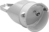
Wall-Vent Flue-Gas Exhausters
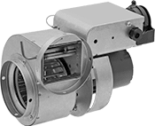 |
Often used for electric-to-gas conversions and renovations, these exhausters allow gas- or oil-fired equipment to be vented through a sidewall rather than a chimney. A thermostat signal starts the exhauster and a sensor ensures proper draft prior to operation. Exhausters have an open dripproof motor enclosure for relatively clean, dry, indoor locations. Use a reducer to vent through ducts with diameters up to 2" wider than the exhauster.
Flue-Gas Exhauster Hoods—A flue-gas exhauster hood (sold separately) is required for the exterior of the sidewall.
Flue-Gas Exhausters | Flue-Gas Exhauster Hoods | ||||||||||
|---|---|---|---|---|---|---|---|---|---|---|---|
For Furnace Heating Cap., BTU/hr | For Duct Diameter | Motor Speed, rpm | Max. Temp., ° F | Housing Material | Mounting Fasteners Included | Each | Each | ||||
24V AC/120V AC—Hardwire | |||||||||||
| 150,000 to 300,000 | 4" | 3,000 | 600 | Steel | Yes | 3972K4 | 0000000 | 3972K13 | 0000000 | ||
| 300,000 to 600,000 | 6" | 3,000 | 600 | Steel | Yes | 3972K7 | 000000 | 3972K18 | 000000 | ||
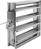
Duct Fire Dampers
For Round Duct
 |
Galvanized Steel—Strong and corrosion resistant, galvanized steel is the most commonly used ductwork material.
Overall | Galvanized Steel | ||||||||
|---|---|---|---|---|---|---|---|---|---|
Duct Size | OD | Ht. | Wd. | Fire Safety Std. | Fusible Link Melting Temp., ° F | Ga. | Each | ||
| 4 | 3 3/4" | 6 3/4" | 6 3/4" | UL 555 | 165 | 22 | 19215K26 | 0000000 | |
| 6 | 5 3/4" | 8 3/4" | 8 3/4" | UL 555 | 165 | 22 | 19215K27 | 000000 | |
| 8 | 7 3/4" | 10 3/4" | 10 3/4" | UL 555 | 165 | 22 | 19215K28 | 000000 | |
| 10 | 9 3/4" | 12 3/4" | 12 3/4" | UL 555 | 165 | 22 | 19215K29 | 000000 | |
| 12 | 11 3/4" | 14 3/4" | 14 3/4" | UL 555 | 165 | 22 | 19215K31 | 000000 | |
For Square Duct
 |
Galvanized Steel—Strong and corrosion resistant, galvanized steel is the most commonly used ductwork material.
For Duct | Overall | Galvanized Steel | ||||||||
|---|---|---|---|---|---|---|---|---|---|---|
Ht. | Wd. | Ht. | Wd. | Dp. | Fire Safety Std. | Fusible Link Melting Temp., ° F | Ga. | Each | ||
| 8" | 8" | 7 3/4" | 7 3/4" | 4 7/8" | UL 555 | 165 | 22 | 2263K29 | 000000 | |
| 12" | 12" | 11 3/4" | 11 3/4" | 4 7/8" | UL 555 | 165 | 22 | 2263K88 | 00000 | |
| 14" | 14" | 13 3/4" | 13 3/4" | 4 7/8" | UL 555 | 165 | 22 | 2263K91 | 00000 | |
| 18" | 18" | 17 3/4" | 17 3/4" | 4 7/8" | UL 555 | 165 | 22 | 2263K93 | 000000 | |
| 24" | 24" | 23 3/4" | 23 3/4" | 4 7/8" | UL 555 | 165 | 22 | 2263K97 | 000000 | |
Airflow-Actuated HVAC Switches
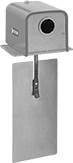 |
Use this switch to sense changes in airflow velocity in duct. The paddle extends into the duct and actuates the switch when airflow reaches the setpoint. Switch is rated NEMA 3R for protection from dirt, falling liquids, and light splashing.
Paddle | ||||||||||||||||
|---|---|---|---|---|---|---|---|---|---|---|---|---|---|---|---|---|
Speed Set Point, fpm | Temp. Range, ° F | Current @ Voltage | Electrical Connection | Switch Designation | For Conduit Trade Size | Knockout Dia. | Material | Ht. | Wd. | For Use Outdoors | Enclosure Rating | Certification | Each | |||
Paddle Sensors | ||||||||||||||||
| 350 to 500 | 32 to 104 | 10 amp @ 240V AC 16 amp @ 120V AC | Screw Terminal | SPDT | 1/2 | 7/8" | Stainless Steel | 6 7/8" | 3 1/8" | Yes | IP43, NEMA 3R | UL Listed, C-UL Listed, CE Marked | 1783K13 | 0000000 | ||
Air-Pressure-Actuated HVAC Switches
 |
Often used to detect clogged air filters and iced air conditioner coils, these switches sense small changes in pressure between two points in your duct.
Pressure Set Point, in. H₂O | Accuracy, in. H₂O | Temp. Range, ° F | Current @ Voltage | Electrical Connection Type | Switch Designation | Max. Pressure, psi | Low Pressure Side Connection | High Pressure Side Inside Connection | High Pressure Side Outside Connection | For Use Outdoors | Enclosure Rating | Certification | Each | |||
|---|---|---|---|---|---|---|---|---|---|---|---|---|---|---|---|---|
Diaphragm Sensors | ||||||||||||||||
| 0.05 to 5 | 0.025 | -40 to 165 | 2.9 amp @ 240V AC 5.8 amp @ 120V AC | Hardwire | SPDT | 1 | 1/8 NPT Female | 1/8 NPT Female | 1/2 NPSM | No | NEMA 1 | CSA Certified, UL Listed | 1795K1 | 0000000 | ||
| 0.05 to 5 | 0.04 | -40 to 165 | 4.9 amp @ 240V AC 9.8 amp @ 120V AC | Hardwire | SPDT | 1 | 1/8 NPT Female | 1/8 NPT Female | 1/2 NPSM | No | NEMA 1 | CSA Certified, UL Listed | 1795K6 | 000000 | ||
Incremental and Proportional HVAC Duct Damper Actuators
 |
Actuators automatically switch between incremental and proportional control to adjust dampers to regulate airflow. Actuators attach to the damper shaft to rotate it open and closed when signaled by a controller (not included).
For Max. Damper Shaft | Overall | |||||||||||||||
|---|---|---|---|---|---|---|---|---|---|---|---|---|---|---|---|---|
Torque, in·lbf | Voltage | Current, amp | Electrical Connection Type | Dia. | Ht. | Wd. | Material | Direction of Operation | Rotation Range | Ht. | Wd. | Dp. | Each | |||
Without Spring Return | ||||||||||||||||
| 90 | 24V AC/24V DC | 0 | Hardwire | 1 1/16" | 3/4" | 3/4" | Plastic | Clockwise, Counterclockwise | 35° to 95° | 6 5/8" | 3 1/4" | 2 1/2" | 1742K91 | 0000000 | ||
| 180 | 24V AC/24V DC | 0 | Hardwire | 1 1/16" | 3/4" | 3/4" | Plastic | Clockwise, Counterclockwise | 35° to 95° | 7 7/8" | 4" | 2 5/8" | 1742K92 | 000000 | ||
| 310 | 24V AC/24V DC | 0 | Hardwire | 1 1/16" | 3/4" | 3/4" | Plastic | Clockwise, Counterclockwise | 35° to 95° | 7 7/8" | 4" | 2 5/8" | 1742K93 | 000000 | ||
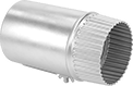
Inline Flue-Gas Exhausters
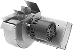 |
Increase airflow through exhaust duct to improve furnace performance. Create a cutout in your duct, insert the blower wheel, and mount the housing to the duct. All have an open dripproof motor enclosure for relatively clean, dry, indoor locations. They cannot be used for sidewall venting applications.
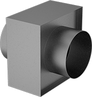
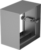
Airflow Dampers for Square Duct
 |
For Duct | Overall | Galvanized Steel | |||||||
|---|---|---|---|---|---|---|---|---|---|
Ht. | Wd. | Ht. | Wd. | Dp. | Ga. | Gasket Material | Each | ||
| 12" | 12" | 11 3/4" | 11 3/4" | 5 1/2" | 16 | Vinyl Plastic | 2041K12 | 0000000 | |
| 14" | 14" | 13 3/4" | 13 3/4" | 5 1/2" | 16 | Vinyl Plastic | 2041K13 | 000000 | |
| 16" | 16" | 15 3/4" | 15 3/4" | 5 1/2" | 16 | Vinyl Plastic | 2041K14 | 000000 | |
| 24" | 24" | 23 3/4" | 23 3/4" | 5 1/2" | 16 | Vinyl Plastic | 2041K22 | 000000 | |
| 36" | 36" | 35 3/4" | 35 3/4" | 5 1/2" | 16 | Vinyl Plastic | 2041K27 | 000000 | |
Barometric Draft Dampers
 |
These dampers improve furnace performance by automatically opening and closing to maintain a consistent airflow despite changing environmental conditions.
Single-Acting Damper—Single-acting dampers open inward to prevent strong drafts from pulling too much heat into the chimney vent.
Double-Acting Damper—Double-acting dampers open both inward and outward to relieve pressure caused by obstructions and downdrafts.
Steel | |||||||
|---|---|---|---|---|---|---|---|
Draft Damper Type | For Duct Size | Ga. | For System Type | Fitting Connection | Each | ||
| Single Acting | 5, 6, 7 | 26 | Coal, Oil | Press Fit | 1782K22 | 0000000 | |
| Single Acting | 7, 8, 9 | 24 | Coal, Oil | Press Fit | 1782K24 | 000000 | |
| Single Acting, Double Acting | 9, 10 | 24 | Coal, Natural Gas, Oil, Propane | Press Fit | 1782K13 | 000000 | |
| Single Acting, Double Acting | 11, 12 | 24 | Coal, Natural Gas, Oil, Propane | Press Fit | 1782K14 | 000000 | |
| Double Acting | 5, 6 | 26 | Natural Gas, Propane | Press Fit | 1782K18 | 000000 | |
| Double Acting | 7, 8 | 26 | Natural Gas, Propane | Press Fit | 1782K12 | 000000 | |
