


Measure your pipe and fittings to identify their pipe size, thread size, schedule, and thread type. Then, find compatible components.


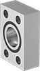
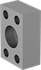
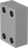
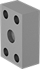
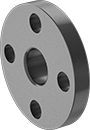
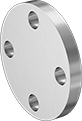
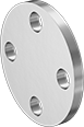
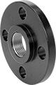
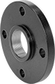
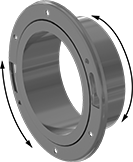
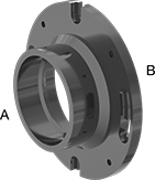
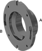
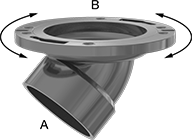
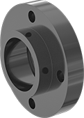
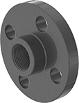
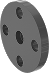
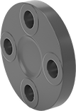
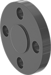
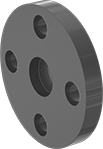
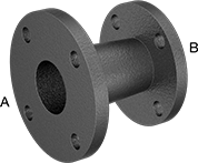
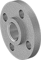
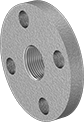
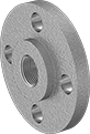
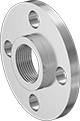
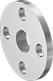
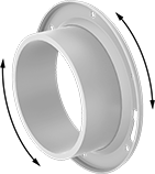
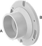
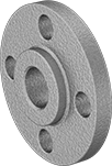
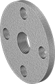
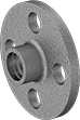
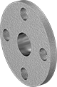
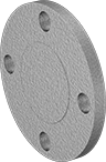
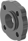
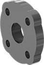
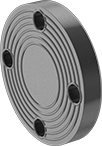
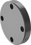
SAE High-Pressure Iron and Steel Threaded Pipe Flanges
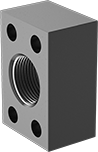 |  |  |
Front | Back (Flat) | Back (O-Ring Groove) |
Dash Size | Bolt Hole | |||||||||||||
|---|---|---|---|---|---|---|---|---|---|---|---|---|---|---|
Pipe Size (A) | Thread Size (A) | SAE Pipe Flange Size (B) | (A) | (B) | Flanged Connection Surface (B) | For Bolt Dia. | Dia. | No. Of | Material | Max. Pressure @ Temp. | Each | |||
NPTF Female | ||||||||||||||
| 3/4 | — | 3/4 | 12 | 12 | Flat | 3/8" | 3/8" | 4 | Steel | 3,000 psi @ 72° F | 2125N1 | 000000 | ||
| 3/4 | — | 3/4 | 12 | 12 | O-Ring Groove | 3/8" | 0.41" | 4 | Steel | 3,000 psi @ 72° F | 2125N14 | 00000 | ||
| 1 | — | 1 | 16 | 16 | Flat | 3/8" | 3/8" | 4 | Steel | 3,000 psi @ 72° F | 2125N11 | 00000 | ||
| 1 | — | 1 | 16 | 16 | O-Ring Groove | 3/8" | 0.41" | 4 | Steel | 3,000 psi @ 72° F | 2125N15 | 00000 | ||
| 1 | — | 1 | 16 | 16 | O-Ring Groove | 10 mm | 10.5 mm | 4 | Steel | 3,000 psi @ 72° F | 2125N19 | 00000 | ||
| 1 1/2 | — | 1 1/2 | 24 | 24 | Flat | 1/2" | 1/2" | 4 | Steel | 3,000 psi @ 72° F | 2125N12 | 00000 | ||
| 1 1/2 | — | 1 1/2 | 24 | 24 | O-Ring Groove | 1/2" | 0.53" | 4 | Steel | 3,000 psi @ 72° F | 2125N16 | 00000 | ||
| 2 | — | 2 | 32 | 32 | Flat | 1/2" | 1/2" | 4 | Steel | 3,000 psi @ 72° F | 2125N13 | 00000 | ||
| 2 | — | 2 | 32 | 32 | O-Ring Groove | 1/2" | 0.53" | 4 | Steel | 3,000 psi @ 72° F | 2125N17 | 00000 | ||
| 2 | — | 2 | 32 | 32 | O-Ring Groove | 12 mm | 13.3 mm | 4 | Steel | 3,000 psi @ 72° F | 2125N21 | 00000 | ||
UN/UNF (SAE Straight) Female | ||||||||||||||
| — | 1 5/16"-12 | 1 | 16 | 16 | O-Ring Groove | 3/8" | 0.41" | 4 | Steel | 3,000 psi @ 72° F | 2125N27 | 00000 | ||
| — | 1 7/8"-12 | 1 1/2 | 24 | 24 | Flat | 1/2" | 1/2" | 4 | Steel | 3,000 psi @ 72° F | 2125N24 | 00000 | ||
| — | 1 7/8"-12 | 1 1/2 | 24 | 24 | O-Ring Groove | 12 mm | 13 mm | 4 | Steel | 3,000 psi @ 72° F | 2125N32 | 00000 | ||
| — | 1 7/8"-12 | 2 | 24 | 32 | O-Ring Groove | 1/2" | 0.53" | 4 | Steel | 3,000 psi @ 72° F | 2125N29 | 00000 | ||
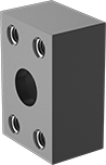
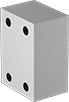
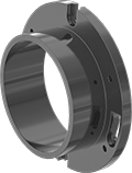
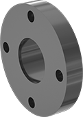
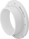
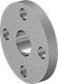
SAE High-Pressure Stainless Steel Unthreaded Pipe Flanges
 |  |  |  |
Flat Front | Flat Back | O-Ring Groove Front | O-Ring Groove Back |
Dash Size | Bolt Hole | 316/316L Stainless Steel | ||||||||||
|---|---|---|---|---|---|---|---|---|---|---|---|---|
Pipe Size (A) | SAE Pipe Flange Size (B) | (A) | (B) | Flanged Connection Surface (B) | For Bolt Dia. | Dia. | No. Of | Max. Pressure @ Temp. | Each | |||
Socket-Connect Female | ||||||||||||
| 3/4 | 3/4 | 12 | 12 | Flat | 3/8" | 0.406" | 4 | 5,000 psi @ 72° F | 1431N11 | 0000000 | ||
| 3/4 | 3/4 | 12 | 12 | O-Ring Groove | 3/8" | 0.406" | 4 | 5,000 psi @ 72° F | 1431N015 | 000000 | ||
| 1 | 1 | 16 | 16 | Flat | 3/8" | 0.406" | 4 | 5,000 psi @ 72° F | 1431N012 | 000000 | ||
| 1 | 1 | 16 | 16 | O-Ring Groove | 3/8" | 0.406" | 4 | 5,000 psi @ 72° F | 1431N016 | 000000 | ||
| 1 1/2 | 1 1/2 | 24 | 24 | Flat | 1/2" | 0.531" | 4 | 3,000 psi @ 72° F | 1431N013 | 000000 | ||
| 1 1/2 | 1 1/2 | 24 | 24 | O-Ring Groove | 1/2" | 0.531" | 4 | 3,000 psi @ 72° F | 1431N017 | 000000 | ||
| 2 | 2 | 32 | 32 | Flat | 1/2" | 0.531" | 4 | 3,000 psi @ 72° F | 1431N014 | 000000 | ||
| 2 | 2 | 32 | 32 | O-Ring Groove | 1/2" | 0.531" | 4 | 3,000 psi @ 72° F | 1431N018 | 000000 | ||


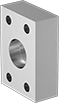
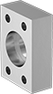
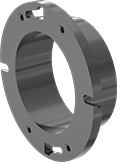
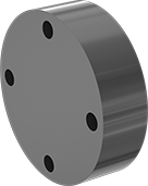
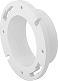
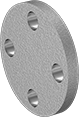
SAE High-Pressure Stainless Steel Threaded Pipe Flanges
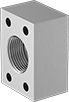 |  |  |  |
Flat Front | Flat Back | O-Ring Groove Front | O-Ring Groove Back |
Dash Size | Bolt Hole | 316/316L Stainless Steel | |||||||||||
|---|---|---|---|---|---|---|---|---|---|---|---|---|---|
Pipe Size (A) | Thread Size (A) | SAE Pipe Flange Size (B) | (A) | (B) | Flanged Connection Surface (B) | For Bolt Dia. | Dia. | No. Of | Max. Pressure @ Temp. | Each | |||
NPTF Female | |||||||||||||
| 3/4 | — | 3/4 | 12 | 12 | O-Ring Groove | 3/8" | 0.406" | 4 | 2,500 psi @ 72° F | 1723N15 | 0000000 | ||
| 1 | — | 1 | 16 | 16 | Flat | 3/8" | 0.312" | 4 | 2,000 psi @ 72° F | 1723N12 | 000000 | ||
| 1 | — | 1 | 16 | 16 | O-Ring Groove | 3/8" | 0.406" | 4 | 2,000 psi @ 72° F | 1723N16 | 000000 | ||
| 1 1/2 | — | 1 1/2 | 24 | 24 | Flat | 1/2" | 0.422" | 4 | 1,000 psi @ 72° F | 1723N13 | 000000 | ||
| 1 1/2 | — | 1 1/2 | 24 | 24 | O-Ring Groove | 1/2" | 0.531" | 4 | 1,000 psi @ 72° F | 1723N17 | 000000 | ||
| 2 | — | 2 | 32 | 32 | Flat | 1/2" | 0.422" | 4 | 1,000 psi @ 72° F | 1723N14 | 000000 | ||
| 2 | — | 2 | 32 | 32 | O-Ring Groove | 1/2" | 0.531" | 4 | 1,000 psi @ 72° F | 1723N18 | 000000 | ||
UN/UNF (SAE Straight) Female | |||||||||||||
| — | 1 5/16"-12 | 1 | 16 | 16 | O-Ring Groove | 3/8" | 0.406" | 4 | 6,000 psi @ 72° F | 1723N29 | 000000 | ||
| — | 2 1/2"-12 | 2 | 32 | 32 | Flat | 1/2" | 0.531" | 4 | 3,000 psi @ 72° F | 1723N27 | 000000 | ||
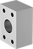
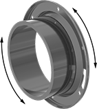
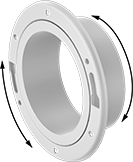
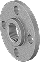
SAE High-Pressure Iron and Steel Unthreaded Pipe Flanges
 |  |
Front | Back (O-Ring Groove) |
Dash Size | Bolt Hole | ||||||||||||
|---|---|---|---|---|---|---|---|---|---|---|---|---|---|
Pipe Size (A) | SAE Pipe Flange Size (B) | (A) | (B) | Flanged Connection Surface (B) | For Bolt Dia. | Dia. | No. Of | Material | Max. Pressure @ Temp. | Each | |||
Socket-Connect Female | |||||||||||||
| 3/4 | 3/4 | 12 | 12 | Flat | 3/8" | 0.41" | 4 | Steel | 3,000 psi @ 72° F | 2125N34 | 000000 | ||
| 3/4 | 3/4 | 12 | 12 | O-Ring Groove | 3/8" | 0.41" | 4 | Steel | 3,000 psi @ 72° F | 2125N38 | 00000 | ||
| 1 | 1 | 16 | 16 | Flat | 3/8" | 0.41" | 4 | Steel | 3,000 psi @ 72° F | 2125N35 | 00000 | ||
| 1 | 1 | 16 | 16 | O-Ring Groove | 3/8" | 0.41" | 4 | Steel | 3,000 psi @ 72° F | 2125N39 | 00000 | ||
| 1 1/2 | 1 1/2 | 24 | 24 | Flat | 1/2" | 1/2" | 4 | Steel | 3,000 psi @ 72° F | 2125N36 | 00000 | ||
| 1 1/2 | 1 1/2 | 24 | 24 | O-Ring Groove | 1/2" | 0.53" | 4 | Steel | 3,000 psi @ 72° F | 2125N4 | 00000 | ||
| 1 1/2 | 1 1/2 | 24 | 24 | O-Ring Groove | 12 mm | 13 mm | 4 | Steel | 3,000 psi @ 72° F | 2125N44 | 00000 | ||
| 2 | 2 | 32 | 32 | Flat | 1/2" | 0.53" | 4 | Steel | 3,000 psi @ 72° F | 2125N37 | 00000 | ||
| 2 | 2 | 32 | 32 | O-Ring Groove | 1/2" | 0.53" | 4 | Steel | 3,000 psi @ 72° F | 2125N41 | 00000 | ||
| 2 | 2 | 32 | 32 | O-Ring Groove | 12 mm | 13 mm | 4 | Steel | 3,000 psi @ 72° F | 2125N45 | 00000 | ||
 |  |
Front | Back (O-Ring Groove) |
Bolt Hole | |||||||||||
|---|---|---|---|---|---|---|---|---|---|---|---|
SAE Pipe Flange Size | Dash Size | Flanged Connection Surface | For Bolt Dia. | Dia. | No. Of | Material | Max. Pressure @ Temp. | Each | |||
Flanged | |||||||||||
| 3/4 | 12 | O-Ring Groove | 3/8" | 0.41" | 4 | Steel | 3,000 psi @ 72° F | 2125N5 | 000000 | ||
| 1 | 16 | Flat | 3/8" | 0.41" | 4 | Steel | 3,000 psi @ 72° F | 2125N47 | 00000 | ||
| 1 | 16 | O-Ring Groove | 3/8" | 0.41" | 4 | Steel | 3,000 psi @ 72° F | 2125N51 | 00000 | ||
| 1 1/2 | 24 | Flat | 1/2" | 1/2" | 4 | Steel | 3,000 psi @ 72° F | 2125N48 | 00000 | ||
| 1 1/2 | 24 | O-Ring Groove | 1/2" | 0.53" | 4 | Steel | 3,000 psi @ 72° F | 2125N52 | 00000 | ||
| 2 | 32 | O-Ring Groove | 1/2" | 0.53" | 4 | Steel | 3,000 psi @ 72° F | 2125N53 | 00000 | ||
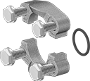
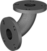
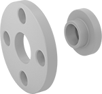
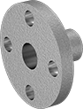
SAE Extreme-Pressure Iron and Steel Threaded Two-Piece Pipe Flanges
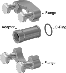 |
Flange |
Bolt Hole | |||||||||||
|---|---|---|---|---|---|---|---|---|---|---|---|
SAE Pipe Flange Size | Dash Size | Flanged Connection Surface | For Bolt Dia. | Dia. | No. Of | Material | Max. Pressure @ Temp. | Each | |||
Flanged | |||||||||||
| 3/4 | 12 | O-Ring Groove | 3/8" | 0.41" | 4 | Steel | 6,000 psi @ 72° F | 2125N66 | 000000 | ||
| 3/4 | 12 | O-Ring Groove | 10 mm | 11 mm | 4 | Steel | 6,000 psi @ 72° F | 2125N71 | 00000 | ||
| 1 | 16 | O-Ring Groove | 0.438" | 0.47" | 4 | Steel | 6,000 psi @ 72° F | 2125N67 | 00000 | ||
| 1 | 16 | O-Ring Groove | 12 mm | 13 mm | 4 | Steel | 6,000 psi @ 72° F | 2125N72 | 00000 | ||
| 1 1/2 | 24 | O-Ring Groove | 5/8" | 0.66" | 4 | Steel | 6,000 psi @ 72° F | 2125N68 | 00000 | ||
| 1 1/2 | 24 | O-Ring Groove | 16 mm | 17 mm | 4 | Steel | 6,000 psi @ 72° F | 2125N7 | 00000 | ||
| 2 | 32 | O-Ring Groove | 3/4" | 0.78" | 4 | Steel | 6,000 psi @ 72° F | 2125N69 | 000000 | ||
| 2 | 32 | O-Ring Groove | 20 mm | 21 mm | 4 | Steel | 6,000 psi @ 72° F | 2125N73 | 000000 | ||
|
Flange |
Pipe Size (A) | For SAE Pipe Flange Size (B) | Dash Size (A) | For Flanged Connection Surface | Material | Max. Pressure @ Temp. | Each | |||
|---|---|---|---|---|---|---|---|---|---|
NPTF Female | |||||||||
| 3/4 | 3/4 | 12 | O-Ring Groove | Steel | 6,000 psi @ 72° F | 2125N86 | 000000 | ||
| 1 | 1 | 16 | O-Ring Groove | Steel | 6,000 psi @ 72° F | 2125N87 | 00000 | ||
| 1 1/2 | 1 1/2 | 24 | O-Ring Groove | Steel | 6,000 psi @ 72° F | 2125N88 | 000000 | ||
| 2 | 2 | 32 | O-Ring Groove | Steel | 6,000 psi @ 72° F | 2125N89 | 000000 | ||
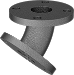
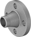
SAE High-Pressure Iron and Steel Threaded Two-Piece Pipe Flanges
|
Flange |
Bolt Hole | |||||||||||
|---|---|---|---|---|---|---|---|---|---|---|---|
SAE Pipe Flange Size | Dash Size | Flanged Connection Surface | For Bolt Dia. | Dia. | No. Of | Material | Max. Pressure @ Temp. | Each | |||
Flanged | |||||||||||
| 1 | 16 | O-Ring Groove | 3/8" | 0.41" | 4 | Steel | 3,000 psi @ 72° F | 2125N59 | 000000 | ||
| 1 | 16 | O-Ring Groove | 10 mm | 11 mm | 4 | Steel | 3,000 psi @ 72° F | 2125N63 | 00000 | ||
| 1 1/2 | 24 | O-Ring Groove | 1/2" | 0.53" | 4 | Steel | 3,000 psi @ 72° F | 2125N6 | 00000 | ||
| 1 1/2 | 24 | O-Ring Groove | 12 mm | 13 mm | 4 | Steel | 3,000 psi @ 72° F | 2125N64 | 00000 | ||
| 2 | 32 | O-Ring Groove | 1/2" | 0.53" | 4 | Steel | 3,000 psi @ 72° F | 2125N61 | 00000 | ||
| 2 | 32 | O-Ring Groove | 12 mm | 13 mm | 4 | Steel | 3,000 psi @ 72° F | 2125N65 | 00000 | ||
SAE High-Pressure Stainless Steel Threaded Two-Piece Pipe Flanges
 |
Flanged O-Ring Groove |
Bolt Hole | 316/316L Stainless Steel | |||||||||
|---|---|---|---|---|---|---|---|---|---|---|
SAE Pipe Flange Size | Dash Size | Flanged Connection Surface | For Bolt Dia. | Dia. | No. Of | Max. Pressure @ Temp. | Each | |||
Flanged | ||||||||||
| 3/4 | 12 | O-Ring Groove | 3/8" | 0.406" | 4 | 5,000 psi @ 72° F | 1723N37 | 0000000 | ||
| 3/4 | 12 | O-Ring Groove | 10 mm | 10 mm | 4 | 5,000 psi @ 72° F | 1723N42 | 000000 | ||
| 1 | 16 | O-Ring Groove | 3/8" | 0.406" | 4 | 4,600 psi @ 72° F | 1723N38 | 000000 | ||
| 1 | 16 | O-Ring Groove | 10 mm | 10 mm | 4 | 4,600 psi @ 72° F | 1723N43 | 000000 | ||
| 1 1/2 | 24 | O-Ring Groove | 1/2" | 0.531" | 4 | 3,000 psi @ 72° F | 1723N39 | 000000 | ||
| 1 1/2 | 24 | O-Ring Groove | 12 mm | 13 mm | 4 | 3,000 psi @ 72° F | 1723N44 | 000000 | ||
| 2 | 32 | O-Ring Groove | 1/2" | 0.531" | 4 | 3,000 psi @ 72° F | 1723N41 | 000000 | ||
| 2 | 32 | O-Ring Groove | 12 mm | 13 mm | 4 | 3,000 psi @ 72° F | 1723N45 | 000000 | ||
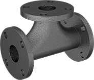
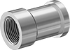 | 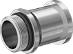 |
Female | Male |
316/316L Stainless Steel | |||||||||
|---|---|---|---|---|---|---|---|---|---|
Pipe Size (A) | Thread Size (A) | For SAE Pipe Flange Size (B) | Dash Size (A) | For Flanged Connection Surface | Max. Pressure @ Temp. | Each | |||
NPTF Female | |||||||||
| 3/4 | — | 3/4 | 12 | O-Ring Groove | 5,000 psi @ 72° F | 1723N51 | 0000000 | ||
| 1 | — | 1 | 16 | O-Ring Groove | 4,600 psi @ 72° F | 1723N52 | 000000 | ||
| 1 1/2 | — | 1 1/2 | 24 | O-Ring Groove | 3,000 psi @ 72° F | 1723N53 | 000000 | ||
| 2 | — | 2 | 32 | O-Ring Groove | 3,000 psi @ 72° F | 1723N54 | 000000 | ||
UN/UNF (SAE Straight) Male | |||||||||
| — | 1 5/16"-12 | 1 | 16 | O-Ring Groove | 4,600 psi @ 72° F | 1723N47 | 000000 | ||
| — | 1 7/8"-12 | 1 1/2 | 24 | O-Ring Groove | 3,000 psi @ 72° F | 1723N48 | 000000 | ||
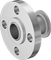
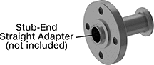
High-Pressure Iron and Steel Unthreaded Pipe Flanges
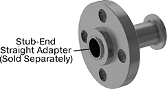 |  |
Stub-End (Front) | Stub-End (Flat Surface on Back) |
Pipe Size | Dash Size | Bolt Hole | |||||||||||||||
|---|---|---|---|---|---|---|---|---|---|---|---|---|---|---|---|---|---|
(A) | (B) | (A) | (B) | Flanged Connection Surface (B) | Flange OD | For Bolt Dia. | Dia. | No. Of | Bolt Circle Dia. | Pressure Class | Material | Max. Pressure @ Temp. | Max. Steam Pressure @ Temp. | Each | |||
Stub-End Female | |||||||||||||||||
| 1/2 | 1/2 | 08 | 08 | Flat | 3 3/4" | 1/2" | 5/8" | 4 | 2 5/8" | 300 | Steel | 600 psi @ 72° F | 300 psi @ 300° F | 6806K353 | 000000 | ||
| 3/4 | 3/4 | 12 | 12 | Flat | 4 5/8" | 5/8" | 3/4" | 4 | 3 1/4" | 300 | Steel | 600 psi @ 72° F | 300 psi @ 300° F | 6806K327 | 00000 | ||
| 1 | 1 | 16 | 16 | Flat | 4 7/8" | 5/8" | 3/4" | 4 | 3 1/2" | 300 | Steel | 600 psi @ 72° F | 300 psi @ 300° F | 6806K328 | 00000 | ||
| 1 1/4 | 1 1/4 | 20 | 20 | Flat | 5 1/4" | 5/8" | 3/4" | 4 | 3 7/8" | 300 | Steel | 600 psi @ 72° F | 300 psi @ 300° F | 6806K329 | 00000 | ||
| 1 1/2 | 1 1/2 | 24 | 24 | Flat | 6 1/8" | 3/4" | 7/8" | 4 | 4 1/2" | 300 | Steel | 600 psi @ 72° F | 300 psi @ 300° F | 6806K331 | 00000 | ||
| 2 | 2 | 32 | 32 | Flat | 6 1/2" | 5/8" | 3/4" | 8 | 5" | 300 | Steel | 600 psi @ 72° F | 300 psi @ 300° F | 6806K332 | 00000 | ||
| 2 1/2 | 2 1/2 | 40 | 40 | Flat | 7 1/2" | 3/4" | 7/8" | 8 | 5 7/8" | 300 | Steel | 600 psi @ 72° F | 300 psi @ 300° F | 6806K333 | 00000 | ||
| 3 | 3 | 48 | 48 | Flat | 8 1/4" | 3/4" | 7/8" | 8 | 6 5/8" | 300 | Steel | 600 psi @ 72° F | 300 psi @ 300° F | 6806K334 | 00000 | ||
| 4 | 4 | 64 | 64 | Flat | 10" | 3/4" | 7/8" | 8 | 7 7/8" | 300 | Steel | 600 psi @ 72° F | 300 psi @ 300° F | 6806K335 | 00000 | ||
| 5 | 5 | — | — | Flat | 11" | 3/4" | 7/8" | 8 | 9 1/4" | 300 | Steel | 600 psi @ 72° F | 300 psi @ 300° F | 6806K351 | 000000 | ||
| 6 | 6 | 96 | 96 | Flat | 12 1/2" | 3/4" | 7/8" | 12 | 10 5/8" | 300 | Steel | 600 psi @ 72° F | 300 psi @ 300° F | 6806K336 | 000000 | ||
| 8 | 8 | — | — | Flat | 15" | 7/8" | 1" | 12 | 13" | 300 | Steel | 600 psi @ 72° F | 300 psi @ 300° F | 6806K352 | 000000 | ||
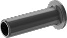 |
Straight Adapter |
Pipe Size | Flange OD | Construction | Pipe Schedule | Finished Material | Each | ||
|---|---|---|---|---|---|---|---|
| 1/2 | 1 3/8" | Seamless | 80 | Steel | 4981T211 | 000000 | |
| 3/4 | 1 1/16" | Seamless | 80 | Steel | 4981T221 | 00000 | |
| 1 | 2" | Seamless | 80 | Steel | 4981T231 | 00000 | |
| 1 1/4 | 2 1/2" | Seamless | 80 | Steel | 4981T241 | 000000 | |
| 1 1/2 | 2 7/8" | Seamless | 80 | Steel | 4981T251 | 000000 | |
| 2 | 3 5/8" | Seamless | 80 | Steel | 4981T261 | 000000 | |
| 2 1/2 | 4 1/8" | Seamless | 80 | Steel | 4981T271 | 000000 | |
| 3 | 5" | Seamless | 80 | Steel | 4981T281 | 000000 | |
| 4 | 6 3/16" | Seamless | 80 | Steel | 4981T291 | 000000 | |
| 5 | 7 5/16" | Seamless | 80 | Steel | 4981T311 | 000000 | |
| 6 | 8 1/2" | Seamless | 80 | Steel | 4981T321 | 000000 | |
| 8 | 10 5/8" | Seamless | 80 | Steel | 4981T322 | 000000 |
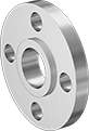
Low-Pressure Stainless Steel Unthreaded Pipe Flanges
 |
Stub End with Straight Adapter (Front) |
Pipe Size | Bolt Hole | 304/304L Stainless Steel | 316/316L Stainless Steel | ||||||||||||
|---|---|---|---|---|---|---|---|---|---|---|---|---|---|---|---|
(A) | (B) | Flanged Connection Surface (B) | Flange OD | For Bolt Dia. | Dia. | No. Of | Bolt Circle Dia. | Pressure Class | Max. Pressure @ Temp. | Each | Each | ||||
Stub End | |||||||||||||||
| 1/2 | 1/2 | Flat | 3 1/2" | 1/2" | 5/8" | 4 | 2 3/8" | 150 | 230 psi @ 72° F | 44685K311 | 000000 | 44695K212 | 000000 | ||
| 3/4 | 3/4 | Flat | 3 7/8" | 1/2" | 5/8" | 4 | 2 3/4" | 150 | 230 psi @ 72° F | 44685K312 | 00000 | 44695K213 | 00000 | ||
| 1 | 1 | Flat | 4 1/4" | 1/2" | 5/8" | 4 | 3 1/8" | 150 | 230 psi @ 72° F | 44685K313 | 00000 | 44695K214 | 00000 | ||
| 1 1/4 | 1 1/4 | Flat | 4 5/8" | 1/2" | 5/8" | 4 | 3 1/2" | 150 | 230 psi @ 72° F | 44685K314 | 00000 | 44695K215 | 00000 | ||
| 1 1/2 | 1 1/2 | Flat | 5" | 1/2" | 5/8" | 4 | 3 7/8" | 150 | 230 psi @ 72° F | 44685K315 | 00000 | 44695K216 | 00000 | ||
| 2 | 2 | Flat | 6" | 5/8" | 3/4" | 4 | 4 3/4" | 150 | 230 psi @ 72° F | 44685K316 | 00000 | 44695K217 | 00000 | ||
| 2 1/2 | 2 1/2 | Flat | 7" | 5/8" | 3/4" | 4 | 5 1/2" | 150 | 230 psi @ 72° F | 44685K317 | 000000 | 44695K218 | 000000 | ||
| 3 | 3 | Flat | 7 1/2" | 5/8" | 3/4" | 4 | 6" | 150 | 230 psi @ 72° F | 44685K318 | 000000 | 44695K219 | 000000 | ||
| 4 | 4 | Flat | 9" | 5/8" | 3/4" | 8 | 7 1/2" | 150 | 230 psi @ 72° F | 44685K319 | 000000 | 44695K221 | 000000 | ||
| 6 | 6 | Flat | 11" | 3/4" | 7/8" | 8 | 9 1/2" | 150 | 230 psi @ 72° F | 44685K161 | 000000 | 44695K151 | 000000 | ||
| 8 | 8 | Flat | 13 1/2" | 3/4" | 7/8" | 8 | 11 3/4" | 150 | 230 psi @ 72° F | 44685K176 | 000000 | 44695K166 | 000000 | ||
| 10 | 10 | Flat | 16" | 7/8" | 1" | 12 | 14 1/4" | 150 | 230 psi @ 72° F | 44685K326 | 000000 | ——— | 0 | ||
| 12 | 12 | Flat | 19" | 7/8" | 1" | 12 | 17" | 150 | 230 psi @ 72° F | 44685K327 | 000000 | 44695K256 | 000000 | ||
 |
Front |
Pipe Size | Bolt Hole | 304 Stainless Steel | 316 Stainless Steel | ||||||||||||
|---|---|---|---|---|---|---|---|---|---|---|---|---|---|---|---|
(A) | (B) | Flanged Connection Surface (B) | Flange OD | For Bolt Dia. | Dia. | No. Of | Bolt Circle Dia. | Pressure Class | Max. Pressure @ Temp. | Each | Each | ||||
Slip-On Weld Female | |||||||||||||||
| 1/2 | 1/2 | Flat | 3 1/2" | 1/2" | 5/8" | 4 | 2 3/8" | 150 | 230 psi @ 72° F | 43505K341 | 000000 | 43615K551 | 000000 | ||
| 3/4 | 3/4 | Flat | 3 7/8" | 1/2" | 5/8" | 4 | 2 3/4" | 150 | 230 psi @ 72° F | 43505K342 | 00000 | 43615K552 | 00000 | ||
| 1 | 1 | Flat | 4 1/4" | 1/2" | 5/8" | 4 | 3 1/8" | 150 | 230 psi @ 72° F | 43505K343 | 00000 | 43615K553 | 00000 | ||
| 1 1/4 | 1 1/4 | Flat | 4 5/8" | 1/2" | 5/8" | 4 | 3 1/2" | 150 | 230 psi @ 72° F | 43505K344 | 00000 | 43615K554 | 00000 | ||
| 1 1/2 | 1 1/2 | Flat | 5" | 1/2" | 5/8" | 4 | 3 7/8" | 150 | 230 psi @ 72° F | 43505K345 | 00000 | 43615K555 | 000000 | ||
| 2 | 2 | Flat | 6" | 5/8" | 3/4" | 4 | 4 3/4" | 150 | 230 psi @ 72° F | 43505K346 | 00000 | 43615K556 | 000000 | ||
| 2 1/2 | 2 1/2 | Flat | 7" | 5/8" | 3/4" | 4 | 5 1/2" | 150 | 230 psi @ 72° F | 43505K347 | 000000 | 43615K557 | 000000 | ||
| 3 | 3 | Flat | 7 1/2" | 5/8" | 3/4" | 4 | 6" | 150 | 230 psi @ 72° F | 43505K348 | 000000 | 43615K558 | 000000 | ||
 |  |
Front | Flat Surface on Back |
Bolt Hole | 304 Stainless Steel | 316 Stainless Steel | ||||||||||||
|---|---|---|---|---|---|---|---|---|---|---|---|---|---|---|
Pipe Size | Flanged Connection Surface | Flange OD | For Bolt Dia. | Dia. | No. Of | Bolt Circle Dia. | Pressure Class | Max. Pressure @ Temp. | Each | Each | ||||
Flanged | ||||||||||||||
| 1/2 | Flat | 3 1/2" | 1/2" | 5/8" | 4 | 2 3/8" | 150 | 230 psi @ 72° F | 43505K381 | 000000 | 43615K571 | 000000 | ||
| 3/4 | Flat | 3 7/8" | 1/2" | 5/8" | 4 | 2 3/4" | 150 | 230 psi @ 72° F | 43505K382 | 00000 | 43615K572 | 00000 | ||
| 1 | Flat | 4 1/4" | 1/2" | 5/8" | 4 | 3 1/8" | 150 | 230 psi @ 72° F | 43505K383 | 00000 | 43615K573 | 00000 | ||
| 1 1/4 | Flat | 4 5/8" | 1/2" | 5/8" | 4 | 3 1/2" | 150 | 230 psi @ 72° F | 43505K384 | 00000 | 43615K574 | 00000 | ||
| 1 1/2 | Flat | 5" | 1/2" | 5/8" | 4 | 3 7/8" | 150 | 230 psi @ 72° F | 43505K385 | 00000 | 43615K575 | 000000 | ||
| 2 | Flat | 6" | 5/8" | 3/4" | 4 | 4 3/4" | 150 | 230 psi @ 72° F | 43505K386 | 000000 | 43615K576 | 000000 | ||
| 2 1/2 | Flat | 7" | 5/8" | 3/4" | 4 | 5 1/2" | 150 | 230 psi @ 72° F | 43505K387 | 000000 | 43615K577 | 000000 | ||
| 3 | Flat | 7 1/2" | 5/8" | 3/4" | 4 | 6" | 150 | 230 psi @ 72° F | 43505K388 | 000000 | 43615K578 | 000000 | ||
 |
Straight Adapter |
304/304L Stainless Steel | 316/316L Stainless Steel | ||||||||
|---|---|---|---|---|---|---|---|---|---|
Pipe Size | Wall Thk. | Flange OD | Construction | Pipe Schedule | Each | Each | |||
| 1/2 | 0.083" | 1 3/8" | Welded | 10 | 45735K291 | 000000 | 43645K391 | 000000 | |
| 1/2 | 0.109" | 1 3/8" | Welded | 40 | 45605K651 | 00000 | 45555K651 | 00000 | |
| 3/4 | 0.083" | 1 11/16" | Welded | 10 | 45735K292 | 00000 | 43645K392 | 00000 | |
| 3/4 | 0.113" | 1 11/16" | Welded | 40 | 45605K652 | 00000 | 45555K652 | 00000 | |
| 1 | 0.109" | 2" | Welded | 10 | 45735K293 | 00000 | 43645K393 | 00000 | |
| 1 | 0.133" | 2" | Welded | 40 | 45605K653 | 00000 | 45555K653 | 00000 | |
| 1 1/4 | 0.109" | 2 1/2" | Welded | 10 | 45735K297 | 00000 | 43645K152 | 00000 | |
| 1 1/4 | 0.14" | 2 1/2" | Welded | 40 | 45605K654 | 00000 | 45555K654 | 00000 | |
| 1 1/2 | 0.109" | 2 7/8" | Welded | 10 | 45735K295 | 00000 | 43645K395 | 00000 | |
| 1 1/2 | 0.145" | 2 7/8" | Welded | 40 | 45605K655 | 00000 | 45555K655 | 00000 | |
| 2 | 0.109" | 3 5/8" | Welded | 10 | 45735K296 | 00000 | 43645K396 | 00000 | |
| 2 | 0.154" | 3 5/8" | Welded | 40 | 45605K656 | 00000 | 45555K656 | 00000 | |
| 2 1/2 | 0.12" | 4 1/8" | Welded | 10 | 45735K311 | 00000 | 43645K153 | 00000 | |
| 2 1/2 | 0.203" | 4 1/8" | Welded | 40 | 45605K657 | 00000 | 45555K657 | 00000 | |
| 3 | 0.12" | 5" | Welded | 10 | 45735K298 | 00000 | 43645K398 | 00000 | |
| 3 | 0.216" | 5" | Welded | 40 | 45605K661 | 00000 | 45555K661 | 00000 | |
| 4 | 0.12" | 6 3/16" | Welded | 10 | 45735K299 | 00000 | 43645K399 | 00000 | |
| 4 | 0.237" | 6 3/16" | Welded | 40 | 45605K663 | 00000 | 45555K663 | 00000 | |
| 6 | 0.134" | 8 1/2" | Welded | 10 | 45735K312 | 000000 | 43645K154 | 000000 | |
| 6 | 0.28" | 8 1/2" | Welded | 40 | 45605K665 | 000000 | 45555K665 | 000000 | |
| 8 | 0.148" | 10 5/8" | Welded | 10 | 45735K116 | 000000 | 43645K155 | 000000 | |
| 8 | 0.322" | 10 5/8" | Welded | 40 | 45605K531 | 000000 | 45555K615 | 000000 | |
| 10 | 0.134" | 12 3/4" | Welded | 10 | 45735K622 | 000000 | ——— | 0 | |
| 12 | — | 15" | Welded | 10 | ——— | 0 | 43645K462 | 000000 | |
| 12 | 0.156" | 15" | Welded | 10 | 45735K623 | 000000 | ——— | 0 | |
FM-Approved Low-Pressure Iron and Steel Threaded Pipe Flanges
 |
Front |
Pipe Size | Bolt Hole | ||||||||||||||
|---|---|---|---|---|---|---|---|---|---|---|---|---|---|---|---|
(A) | (B) | Flanged Connection Surface (B) | Flange OD | For Bolt Dia. | Dia. | No. Of | Bolt Circle Dia. | Material | Max. Pressure @ Temp. | Max. Steam Pressure @ Temp. | Certification | Each | |||
NPT Female | |||||||||||||||
| 3/4 | 3/4 | Flat | 3 7/8" | 1/2" | 5/8" | 4 | 2 3/4" | Cast Iron | 125 psi @ 72° F | 125 psi @ 350° F | FM Approved | 68185K111 | 000000 | ||
| 1 | 1 | Flat | 4 1/4" | 1/2" | 5/8" | 4 | 3 1/8" | Cast Iron | 125 psi @ 72° F | 125 psi @ 350° F | FM Approved, UL Listed | 68185K112 | 00000 | ||
| 1 1/4 | 1 1/4 | Flat | 4 5/8" | 1/2" | 5/8" | 4 | 3 1/2" | Cast Iron | 125 psi @ 72° F | 125 psi @ 350° F | FM Approved, UL Listed | 68185K113 | 00000 | ||
| 1 1/2 | 1 1/2 | Flat | 5" | 1/2" | 5/8" | 4 | 3 7/8" | Cast Iron | 125 psi @ 72° F | 125 psi @ 350° F | FM Approved, UL Listed | 68185K114 | 00000 | ||
| 2 | 2 | Flat | 6" | 5/8" | 3/4" | 4 | 4 3/4" | Cast Iron | 125 psi @ 72° F | 125 psi @ 350° F | FM Approved, UL Listed | 68185K115 | 00000 | ||
| 2 1/2 | 2 1/2 | Flat | 7" | 5/8" | 3/4" | 4 | 5 1/2" | Cast Iron | 125 psi @ 72° F | 125 psi @ 350° F | FM Approved, UL Listed | 68185K116 | 00000 | ||
| 3 | 3 | Flat | 7 1/2" | 5/8" | 3/4" | 4 | 6" | Cast Iron | 125 psi @ 72° F | 125 psi @ 350° F | FM Approved, UL Listed | 68185K117 | 00000 | ||
| 4 | 4 | Flat | 9" | 5/8" | 3/4" | 8 | 7 1/2" | Cast Iron | 125 psi @ 72° F | 125 psi @ 350° F | FM Approved, UL Listed | 68185K118 | 000000 | ||
| 5 | 5 | Flat | 10" | 3/4" | 7/8" | 8 | 8 1/2" | Cast Iron | 125 psi @ 72° F | 125 psi @ 350° F | FM Approved, UL Listed | 68185K131 | 000000 | ||
| 6 | 6 | Flat | 11" | 3/4" | 7/8" | 8 | 9 1/2" | Cast Iron | 125 psi @ 72° F | 125 psi @ 350° F | FM Approved, UL Listed | 68185K132 | 000000 | ||
| 8 | 8 | Flat | 13 1/2" | 3/4" | 7/8" | 8 | 11 3/4" | Cast Iron | 125 psi @ 72° F | 125 psi @ 350° F | FM Approved, UL Listed | 68185K133 | 000000 | ||
 |  |
Reducing Flange | Front |
Bolt Hole | |||||||||||||||
|---|---|---|---|---|---|---|---|---|---|---|---|---|---|---|---|
Pipe Size (A) | For Flange Pipe Size (B) | Flanged Connection Surface (B) | Flange OD | For Bolt Dia. | Dia. | No. Of | Bolt Circle Dia. | Material | Max. Pressure @ Temp. | Max. Steam Pressure @ Temp. | Certification | Each | |||
NPT Female | |||||||||||||||
| 2 | 2 1/2 | Flat | 7" | 5/8" | 3/4" | 4 | 5 1/2" | Cast Iron | 175 psi @ 72° F | 125 psi @ 350° F | FM Approved | 68185K101 | 0000000 | ||
| 2 | 3 | Flat | 7 1/2" | 5/8" | 3/4" | 4 | 6" | Cast Iron | 175 psi @ 72° F | 125 psi @ 350° F | FM Approved | 68185K102 | 000000 | ||
| 2 | 4 | Flat | 9" | 5/8" | 3/4" | 8 | 7 1/2" | Cast Iron | 175 psi @ 72° F | 125 psi @ 350° F | FM Approved | 68185K103 | 000000 | ||
| 3 | 4 | Flat | 9" | 5/8" | 3/4" | 8 | 7 1/2" | Cast Iron | 175 psi @ 72° F | 125 psi @ 350° F | FM Approved | 68185K104 | 000000 | ||
| 4 | 6 | Flat | 11" | 3/4" | 7/8" | 8 | 9 1/2" | Cast Iron | 175 psi @ 72° F | 125 psi @ 350° F | FM Approved | 68185K105 | 000000 | ||
High-Pressure Stainless Steel Unthreaded Pipe Flanges
|
Stub End with Straight Adapter (Front) |
Pipe Size | Dash Size | Bolt Hole | 304/304L Stainless Steel | 316/316L Stainless Steel | ||||||||||||||
|---|---|---|---|---|---|---|---|---|---|---|---|---|---|---|---|---|---|---|
(A) | (B) | (A) | (B) | Flanged Connection Surface (B) | Flange OD | For Bolt Dia. | Dia. | No. Of | Bolt Circle Dia. | Pressure Class | Max. Pressure @ Temp. | Max. Steam Pressure @ Temp. | Each | Each | ||||
Stub End | ||||||||||||||||||
| 3/4 | 3/4 | 12 | 12 | Flat | 4 5/8" | 5/8" | 0.75" | 4 | 3 1/4" | 300 | 600 psi @ 72° F | 300 psi @ 360° F | 4448T298 | 000000 | ——— | 0 | ||
| 1 | 1 | 16 | 16 | Flat | 4 7/8" | 5/8" | 0.75" | 4 | 3 1/2" | 300 | 600 psi @ 72° F | 300 psi @ 360° F | 4448T299 | 00000 | 4452T319 | 000000 | ||
| 1 | 1 | 16 | 16 | Flat | 4 7/8" | 5/8" | 0.75" | 4 | 3 1/2" | 600 | 1,200 psi @ 72° F | 840 psi @ 400° F | 1538N77 | 00000 | ——— | 0 | ||
| 1 1/2 | 1 1/2 | 24 | 24 | Flat | 6 1/8" | 3/4" | 0.875" | 4 | 4 1/2" | 300 | 600 psi @ 72° F | 300 psi @ 360° F | 4448T312 | 000000 | 4452T322 | 000000 | ||
| 2 | 2 | 32 | 32 | Flat | 6 1/2" | 5/8" | 0.75" | 8 | 5" | 300 | 600 psi @ 72° F | 300 psi @ 360° F | 4448T313 | 000000 | 4452T323 | 000000 | ||
| 2 1/2 | 2 1/2 | 40 | 40 | Flat | 7 1/2" | 3/4" | 0.875" | 8 | 5 7/8" | 300 | 600 psi @ 72° F | 300 psi @ 360° F | 4448T314 | 000000 | 4452T324 | 000000 | ||
| 3 | 3 | 48 | 48 | Flat | 8 1/4" | 3/4" | 0.875" | 8 | 6 5/8" | 300 | 600 psi @ 72° F | 300 psi @ 360° F | 4448T315 | 000000 | 4452T325 | 000000 | ||
| 4 | 4 | 64 | 64 | Flat | 10" | 3/4" | 0.875" | 8 | 7 7/8" | 300 | 600 psi @ 72° F | 300 psi @ 360° F | 4448T262 | 000000 | ——— | 0 | ||
| 4 | 4 | 64 | 64 | Flat | 10 3/4" | 7/8" | 1" | 8 | 8 1/2" | 600 | 1,200 psi @ 72° F | 840 psi @ 400° F | 1538N84 | 000000 | ——— | 0 | ||
| 6 | 6 | 96 | 96 | Flat | 12 1/2" | 3/4" | 0.875" | 12 | 10 5/8" | 300 | 600 psi @ 72° F | 300 psi @ 360° F | 4448T263 | 000000 | ——— | 0 | ||
|
Straight Adapter |
304/304L Stainless Steel | 316/316L Stainless Steel | ||||||||
|---|---|---|---|---|---|---|---|---|---|
Pipe Size | Wall Thk. | Flange OD | Construction | Pipe Schedule | Each | Each | |||
| 3/4 | 0.113" | 1 11/16" | Welded | 40 | 45605K652 | 000000 | ——— | 0 | |
| 1 | 0.133" | 2" | Welded | 40 | 45605K653 | 00000 | 45555K653 | 000000 | |
| 1 1/2 | 0.145" | 2 7/8" | Welded | 40 | 45605K655 | 00000 | 45555K655 | 00000 | |
| 2 | 0.154" | 3 5/8" | Welded | 40 | 45605K656 | 00000 | 45555K656 | 00000 | |
| 2 1/2 | 0.203" | 4 1/8" | Welded | 40 | 45605K657 | 00000 | 45555K657 | 00000 | |
| 3 | 0.216" | 5" | Welded | 40 | 45605K661 | 00000 | 45555K661 | 00000 | |
| 4 | 0.237" | 6 3/16" | Welded | 40 | 45605K663 | 00000 | ——— | 0 | |
| 6 | 0.28" | 8 1/2" | Welded | 40 | 45605K665 | 000000 | ——— | 0 | |
Drain, Waste, and Vent ABS Pipe Flanges for Chemicals
 |  |
Front | Flat Surface on Back |
Pipe Size | Bolt Hole | ||||||||||||||
|---|---|---|---|---|---|---|---|---|---|---|---|---|---|---|---|
(A) | (B) | Flanged Connection Surface (B) | Flange OD | For Bolt Dia. | Dia. | No. Of | Bolt Circle Dia. | Pipe Schedule | Material | Color | Max. Pressure @ Temp. | Each | |||
Cement Socket Female | |||||||||||||||
| 4 | 4 | Flat | 7" | 1/4" | 1/4" | 4 | 6" | 40 | ABS | Black | Not Rated | 1608T181 | 000000 | ||
 |  |
Front | Flat Surface on Back |
Pipe Size | Bolt Hole | ||||||||||||||
|---|---|---|---|---|---|---|---|---|---|---|---|---|---|---|---|
(A) | (B) | Flanged Connection Surface (B) | Flange OD | For Bolt Dia. | Dia. | No. Of | Bolt Circle Dia. | Pipe Schedule | Material | Color | Max. Pressure @ Temp. | Each | |||
Cement Socket Female | |||||||||||||||
| 4 | 4 | Flat | 7" | 1/4" | 1/4" | 6 | 6 1/8" | 40 | ABS | Black | Not Rated | 1608T182 | 000000 | ||
 |  |
Front | Flat Surface on Back |
Pipe Size | Bolt Hole | ||||||||||||||
|---|---|---|---|---|---|---|---|---|---|---|---|---|---|---|---|
(A) | (B) | Flanged Connection Surface (B) | Flange OD | For Bolt Dia. | Dia. | No. Of | Bolt Circle Dia. | Pipe Schedule | Material | Color | Max. Pressure @ Temp. | Each | |||
Cement Socket Female | |||||||||||||||
| 3 | 4 | Flat | 7" | 1/4" | 1/4" | 4 | 6" | 40 | ABS | Black | Not Rated | 1608T183 | 000000 | ||
 |
Cement Socket Female |
Pipe Size | Bolt Hole | ||||||||||||||
|---|---|---|---|---|---|---|---|---|---|---|---|---|---|---|---|
(A) | (B) | Flanged Connection Surface (B) | Flange OD | For Bolt Dia. | Dia. | No. Of | Bolt Circle Dia. | Pipe Schedule | Material | Color | Max. Pressure @ Temp. | Each | |||
Cement Socket Female | |||||||||||||||
| 3 | 4 | Flat | 7" | 3/16" | 1/4" | 6 | 6 1/8" | 40 | ABS | Black | Not Rated | 1608T201 | 000000 | ||
Fiberglass Pipe Flanges for Chemicals
 |  |
Front | Flat Surface on Back |
Pipe Size | Bolt Hole | |||||||||||||
|---|---|---|---|---|---|---|---|---|---|---|---|---|---|---|
(A) | (B) | Flanged Connection Surface (B) | Flange OD | For Bolt Dia. | Dia. | No. Of | Bolt Circle Dia. | Material | Color | Max. Pressure @ Temp. | Each | |||
Cement Socket Female | ||||||||||||||
| 1 1/2 | 1 1/2 | Flat | 5" | 1/2" | 5/8" | 4 | 3 7/8" | Fiberglass | Black | 300 psi @ 72° F | 2761N38 | 0000000 | ||
| 2 | 2 | Flat | 6" | 5/8" | 3/4" | 4 | 4 3/4" | Fiberglass | Black | 250 psi @ 72° F | 2761N39 | 000000 | ||
| 3 | 3 | Flat | 7 1/2" | 5/8" | 3/4" | 4 | 6" | Fiberglass | Black | 250 psi @ 72° F | 2761N41 | 000000 | ||
| 4 | 4 | Flat | 9" | 5/8" | 3/4" | 8 | 7 1/2" | Fiberglass | Black | 150 psi @ 72° F | 2761N42 | 000000 | ||
 |
Flanged Flat |
Bolt Hole | |||||||||||||
|---|---|---|---|---|---|---|---|---|---|---|---|---|---|
Pipe Size | Flanged Connection Surface | Flange OD | For Bolt Dia. | Dia. | No. Of | Bolt Circle Dia. | Material | Color | Max. Pressure @ Temp. | Each | |||
Flanged | |||||||||||||
| 1 1/2 | Flat | 5" | 1/2" | 5/8" | 4 | 3 7/8" | Fiberglass | Black | 300 psi @ 72° F | 2761N34 | 0000000 | ||
| 2 | Flat | 6" | 5/8" | 3/4" | 4 | 4 3/4" | Fiberglass | Black | 250 psi @ 72° F | 2761N35 | 000000 | ||
| 3 | Flat | 7 1/2" | 5/8" | 3/4" | 4 | 6" | Fiberglass | Black | 250 psi @ 72° F | 2761N36 | 000000 | ||
| 4 | Flat | 9" | 5/8" | 3/4" | 8 | 7 1/2" | Fiberglass | Black | 150 psi @ 72° F | 2761N37 | 000000 | ||
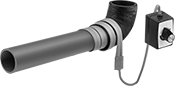 |
Voltage, V AC | Current, amp | Max. Heat Output, ° F | Lg., ft. | Wd. | Thk. | Cord Lg., ft. | Each | ||
|---|---|---|---|---|---|---|---|---|---|
| 120 | 15 | 270 | 6 | 1" | 1/8" | 6 | 2905N52 | 0000000 |
Low-Pressure Iron and Steel Unthreaded Pipe Flanges
 |  |
Stub-End Flange with Straight Adapter: Front | Stub End: Flat Surface on Back |
Pipe Size | Bolt Hole | ||||||||||||||
|---|---|---|---|---|---|---|---|---|---|---|---|---|---|---|---|
(A) | (B) | Flanged Connection Surface (B) | Flange OD | For Bolt Dia. | Dia. | No. Of | Bolt Circle Dia. | Pressure Class | Material | Max. Pressure @ Temp. | Max. Steam Pressure @ Temp. | Each | |||
Stub-End Female | |||||||||||||||
| 1/2 | 1/2 | Flat | 3 1/2" | 1/2" | 5/8" | 4 | 2 3/8" | 150 | Steel | 285 psi @ 72° F | 150 psi @ 300° F | 68095K422 | 000000 | ||
| 3/4 | 3/4 | Flat | 3 7/8" | 1/2" | 5/8" | 4 | 2 3/4" | 150 | Steel | 285 psi @ 72° F | 150 psi @ 300° F | 68095K385 | 00000 | ||
| 1 | 1 | Flat | 4 1/4" | 1/2" | 5/8" | 4 | 3 1/8" | 150 | Steel | 285 psi @ 72° F | 150 psi @ 300° F | 68095K386 | 00000 | ||
| 1 1/4 | 1 1/4 | Flat | 4 5/8" | 1/2" | 5/8" | 4 | 3 1/2" | 150 | Steel | 285 psi @ 72° F | 150 psi @ 300° F | 68095K387 | 00000 | ||
| 1 1/2 | 1 1/2 | Flat | 5" | 1/2" | 5/8" | 4 | 3 7/8" | 150 | Steel | 285 psi @ 72° F | 150 psi @ 300° F | 68095K388 | 00000 | ||
| 2 | 2 | Flat | 6" | 5/8" | 3/4" | 4 | 4 3/4" | 150 | Steel | 285 psi @ 72° F | 150 psi @ 300° F | 68095K389 | 00000 | ||
| 2 1/2 | 2 1/2 | Flat | 7" | 5/8" | 3/4" | 4 | 5 1/2" | 150 | Steel | 285 psi @ 72° F | 150 psi @ 300° F | 68095K391 | 00000 | ||
| 3 | 3 | Flat | 7 1/2" | 5/8" | 3/4" | 4 | 6" | 150 | Steel | 285 psi @ 72° F | 150 psi @ 300° F | 68095K392 | 00000 | ||
| 4 | 4 | Flat | 9" | 5/8" | 3/4" | 8 | 7 1/2" | 150 | Steel | 285 psi @ 72° F | 150 psi @ 300° F | 68095K393 | 00000 | ||
| 5 | 5 | Flat | 10" | 3/4" | 7/8" | 8 | 8 1/2" | 150 | Steel | 285 psi @ 72° F | 150 psi @ 300° F | 68095K419 | 00000 | ||
| 6 | 6 | Flat | 11" | 3/4" | 7/8" | 8 | 9 1/2" | 150 | Steel | 285 psi @ 72° F | 150 psi @ 300° F | 68095K394 | 00000 | ||
| 8 | 8 | Flat | 13 1/2" | 3/4" | 7/8" | 8 | 11 3/4" | 150 | Steel | 285 psi @ 72° F | 150 psi @ 300° F | 68095K421 | 000000 | ||
| 10 | 10 | Flat | 16" | 7/8" | 1" | 12 | 14 1/4" | 150 | Steel | 285 psi @ 72° F | 150 psi @ 300° F | 68095K55 | 000000 | ||
| 12 | 12 | Flat | 19" | 7/8" | 1" | 12 | 17" | 150 | Steel | 285 psi @ 72° F | 150 psi @ 300° F | 68095K56 | 000000 | ||
|
Straight Adapter |
Pipe Size | Flange OD | Construction | Pipe Schedule | Finished Material | Each | ||
|---|---|---|---|---|---|---|---|
| 1/2 | 1 3/8" | Seamless | 40 | Steel | 43425K115 | 000000 | |
| 3/4 | 1 11/16" | Seamless | 40 | Steel | 43425K125 | 00000 | |
| 1 | 2" | Seamless | 40 | Steel | 43425K135 | 00000 | |
| 1 1/4 | 2 1/2" | Seamless | 40 | Steel | 43425K145 | 000000 | |
| 1 1/2 | 2 7/8" | Seamless | 40 | Steel | 43425K155 | 000000 | |
| 2 | 3 5/8" | Seamless | 40 | Steel | 43425K165 | 000000 | |
| 2 1/2 | 4 1/8" | Seamless | 40 | Steel | 43425K175 | 000000 | |
| 3 | 5" | Seamless | 40 | Steel | 43425K185 | 000000 | |
| 4 | 6 3/16" | Seamless | 40 | Steel | 43425K215 | 000000 | |
| 6 | 8 1/2" | Seamless | 40 | Steel | 43425K235 | 000000 | |
| 8 | 10 5/8" | Seamless | 40 | Steel | 43425K245 | 000000 |
Thick-Wall Plastic Pipe Flanges for Water
 |  |
Front | Flat Surface on Back |
Pipe Size | Bolt Hole | ||||||||||||||
|---|---|---|---|---|---|---|---|---|---|---|---|---|---|---|---|
(A) | (B) | Flanged Connection Surface (B) | Flange OD | For Bolt Dia. | Dia. | No. Of | Bolt Circle Dia. | Pressure Class | Material | Color | Food Industry Std. | Each | |||
NPT Female | |||||||||||||||
| 1/2 | 1/2 | Flat | 3 1/2" | 1/2" | 5/8" | 4 | 2 11/32" | 150 | PVC | Dark Gray | NSF/ANSI 61 | 4596K152 | 000000 | ||
| 3/4 | 3/4 | Flat | 3 7/8" | 1/2" | 5/8" | 4 | 2 3/4" | 150 | PVC | Dark Gray | NSF/ANSI 61 | 4596K153 | 00000 | ||
| 1 | 1 | Flat | 4 1/4" | 1/2" | 5/8" | 4 | 3 1/8" | 150 | PVC | Dark Gray | NSF/ANSI 61 | 4596K154 | 00000 | ||
| 1 1/4 | 1 1/4 | Flat | 4 5/8" | 1/2" | 5/8" | 4 | 3 15/32" | 150 | PVC | Dark Gray | NSF/ANSI 61 | 4596K155 | 00000 | ||
| 1 1/2 | 1 1/2 | Flat | 5" | 1/2" | 5/8" | 4 | 3 7/8" | 150 | PVC | Dark Gray | NSF/ANSI 61 | 4596K156 | 00000 | ||
| 2 | 2 | Flat | 6 3/32" | 5/8" | 3/4" | 4 | 4 23/32" | 150 | PVC | Dark Gray | NSF/ANSI 61 | 4596K157 | 00000 | ||
| 2 1/2 | 2 1/2 | Flat | 7" | 5/8" | 3/4" | 4 | 5 15/32" | 150 | PVC | Dark Gray | NSF/ANSI 61 | 4596K161 | 00000 | ||
| 3 | 3 | Flat | 7 1/2" | 5/8" | 3/4" | 4 | 6" | 150 | PVC | Dark Gray | NSF/ANSI 61 | 4596K158 | 00000 | ||
| 4 | 4 | Flat | 9 3/32" | 5/8" | 3/4" | 8 | 7 7/16" | 150 | PVC | Dark Gray | NSF/ANSI 61 | 4596K159 | 00000 | ||
Cement Socket Female | |||||||||||||||
| 1/2 | 1/2 | Flat | 3 1/2" | 1/2" | 5/8" | 4 | 2 11/32" | 150 | PVC | Dark Gray | NSF/ANSI 61 | 4881K212 | 0000 | ||
| 3/4 | 3/4 | Flat | 3 7/8" | 1/2" | 5/8" | 4 | 2 3/4" | 150 | PVC | Dark Gray | NSF/ANSI 61 | 4881K213 | 0000 | ||
| 1 | 1 | Flat | 4 1/4" | 1/2" | 5/8" | 4 | 3 3/32" | 150 | PVC | Dark Gray | NSF/ANSI 61 | 4881K214 | 0000 | ||
| 1 1/4 | 1 1/4 | Flat | 4 5/8" | 1/2" | 5/8" | 4 | 3 7/16" | 150 | PVC | Dark Gray | NSF/ANSI 61 | 4881K215 | 00000 | ||
| 1 1/2 | 1 1/2 | Flat | 5" | 1/2" | 5/8" | 4 | 3 27/32" | 150 | PVC | Dark Gray | NSF/ANSI 61 | 4881K216 | 00000 | ||
| 2 | 2 | Flat | 6" | 5/8" | 3/4" | 4 | 4 3/4" | 150 | PVC | Dark Gray | NSF/ANSI 61 | 4881K217 | 00000 | ||
| 2 1/2 | 2 1/2 | Flat | 7" | 5/8" | 3/4" | 4 | 5 1/2" | 150 | PVC | Dark Gray | NSF/ANSI 61 | 4881K223 | 00000 | ||
| 3 | 3 | Flat | 7 1/2" | 5/8" | 3/4" | 4 | 6" | 150 | PVC | Dark Gray | NSF/ANSI 61 | 4881K218 | 00000 | ||
| 4 | 4 | Flat | 9" | 5/8" | 3/4" | 8 | 7 7/16" | 150 | PVC | Dark Gray | NSF/ANSI 61 | 4881K219 | 00000 | ||
| 6 | 6 | Flat | 11" | 3/4" | 7/8" | 8 | 9 1/2" | 150 | PVC | Dark Gray | NSF/ANSI 61 | 4881K221 | 00000 | ||
| 8 | 8 | Flat | 13 1/2" | 3/4" | 7/8" | 8 | 11 3/4" | 150 | PVC | Dark Gray | NSF/ANSI 61 | 4881K224 | 000000 | ||
 |  |
Front | Back |
Bolt Hole | ||||||||||||||
|---|---|---|---|---|---|---|---|---|---|---|---|---|---|---|
Pipe Size | Flanged Connection Surface | Flange OD | For Bolt Dia. | Dia. | No. Of | Bolt Circle Dia. | Pressure Class | Material | Color | Food Industry Std. | Each | |||
Flanged | ||||||||||||||
| 1/2 | Flat | 3 1/2" | 1/2" | 5/8" | 4 | 2 3/8" | 150 | PVC | Dark Gray | NSF/ANSI 61 | 4881K962 | 000000 | ||
| 3/4 | Flat | 3 7/8" | 1/2" | 5/8" | 4 | 2 3/4" | 150 | PVC | Dark Gray | NSF/ANSI 61 | 4881K963 | 00000 | ||
| 1 | Flat | 4 1/4" | 1/2" | 5/8" | 4 | 3 1/8" | 150 | PVC | Dark Gray | NSF/ANSI 61 | 4881K964 | 00000 | ||
| 1 1/4 | Flat | 4 5/8" | 1/2" | 5/8" | 4 | 3 1/2" | 150 | PVC | Dark Gray | NSF/ANSI 61 | 4881K965 | 00000 | ||
| 1 1/2 | Flat | 5" | 1/2" | 5/8" | 4 | 3 7/8" | 150 | PVC | Dark Gray | NSF/ANSI 61 | 4881K966 | 00000 | ||
| 2 | Flat | 6" | 5/8" | 3/4" | 4 | 4 3/4" | 150 | PVC | Dark Gray | NSF/ANSI 61 | 4881K967 | 00000 | ||
| 2 1/2 | Flat | 7" | 5/8" | 3/4" | 4 | 5 1/2" | 150 | PVC | Dark Gray | NSF/ANSI 61 | 4881K968 | 00000 | ||
| 3 | Flat | 7 1/2" | 5/8" | 3/4" | 4 | 6" | 150 | PVC | Dark Gray | NSF/ANSI 61 | 4881K969 | 00000 | ||
| 4 | Flat | 9" | 5/8" | 3/4" | 8 | 7 1/2" | 150 | PVC | Dark Gray | NSF/ANSI 61 | 4881K971 | 000000 | ||
| 5 | Flat | 10 1/16" | 3/4" | 7/8" | 8 | 8 1/2" | 150 | PVC | Dark Gray | NSF/ANSI 61 | 4881K107 | 000000 | ||
| 6 | Flat | 11" | 3/4" | 7/8" | 8 | 9 1/2" | 150 | PVC | Dark Gray | NSF/ANSI 61 | 4881K972 | 000000 | ||
| 8 | Flat | 13 1/2" | 3/4" | 7/8" | 8 | 11 3/4" | 150 | PVC | Dark Gray | NSF/ANSI 61 | 4881K973 | 000000 | ||
 |
Applicator-Top Can |
Container | |||||
|---|---|---|---|---|---|
Size, fl. oz. | Type | Temp. Range, ° F | Each | ||
| 8 | Applicator-Top Can | -100 to 600 | 4586K9 | 000000 | |
CPVC Pipe Flanges for Chemicals
 |  |
Front | Flat Surface on Back |
Pipe Size | Bolt Hole | ||||||||||||||
|---|---|---|---|---|---|---|---|---|---|---|---|---|---|---|---|
(A) | (B) | Flanged Connection Surface (B) | Flange OD | For Bolt Dia. | Dia. | No. Of | Bolt Circle Dia. | Pressure Class | Material | Color | Food Industry Std. | Each | |||
NPT Female | |||||||||||||||
| 1/2 | 1/2 | Flat | 3 1/2" | 1/2" | 5/8" | 4 | 2 3/8" | 150 | CPVC | Light Gray | NSF/ANSI 61 | 4589K82 | 000000 | ||
| 3/4 | 3/4 | Flat | 3 7/8" | 1/2" | 5/8" | 4 | 2 3/4" | 150 | CPVC | Light Gray | NSF/ANSI 61 | 4589K83 | 00000 | ||
| 1 | 1 | Flat | 4 1/4" | 1/2" | 5/8" | 4 | 3 1/8" | 150 | CPVC | Light Gray | NSF/ANSI 61 | 4589K84 | 00000 | ||
| 1 1/4 | 1 1/4 | Flat | 4 5/8" | 1/2" | 5/8" | 4 | 3 1/2" | 150 | CPVC | Light Gray | NSF/ANSI 61 | 4589K85 | 00000 | ||
| 1 1/2 | 1 1/2 | Flat | 5" | 1/2" | 5/8" | 4 | 3 7/8" | 150 | CPVC | Light Gray | NSF/ANSI 61 | 4589K86 | 00000 | ||
| 2 | 2 | Flat | 6" | 5/8" | 3/4" | 4 | 4 3/4" | 150 | CPVC | Light Gray | NSF/ANSI 61 | 4589K87 | 00000 | ||
| 2 1/2 | 2 1/2 | Flat | 7" | 5/8" | 3/4" | 4 | 5 1/2" | 150 | CPVC | Light Gray | NSF/ANSI 61 | 4589K132 | 000000 | ||
| 3 | 3 | Flat | 7 1/2" | 5/8" | 3/4" | 4 | 6" | 150 | CPVC | Light Gray | NSF/ANSI 61 | 4589K88 | 00000 | ||
| 4 | 4 | Flat | 9" | 5/8" | 3/4" | 8 | 7 1/2" | 150 | CPVC | Light Gray | NSF/ANSI 61 | 4589K89 | 00000 | ||
Cement Socket Female | |||||||||||||||
| 1/2 | 1/2 | Flat | 3 1/2" | 1/2" | 5/8" | 4 | 2 3/8" | 150 | CPVC | Light Gray | NSF/ANSI 61 | 6826K112 | 00000 | ||
| 3/4 | 3/4 | Flat | 3 7/8" | 1/2" | 5/8" | 4 | 2 3/4" | 150 | CPVC | Light Gray | NSF/ANSI 61 | 6826K113 | 00000 | ||
| 1 | 1 | Flat | 4 1/4" | 1/2" | 5/8" | 4 | 3 3/32" | 150 | CPVC | Light Gray | NSF/ANSI 61 | 6826K114 | 00000 | ||
| 1 1/4 | 1 1/4 | Flat | 4 5/8" | 1/2" | 5/8" | 4 | 3 1/2" | 150 | CPVC | Light Gray | NSF/ANSI 61 | 6826K115 | 00000 | ||
| 1 1/2 | 1 1/2 | Flat | 5" | 1/2" | 5/8" | 4 | 3 7/8" | 150 | CPVC | Light Gray | NSF/ANSI 61 | 6826K116 | 00000 | ||
| 2 | 2 | Flat | 6" | 5/8" | 3/4" | 4 | 4 3/4" | 150 | CPVC | Light Gray | NSF/ANSI 61 | 6826K117 | 00000 | ||
| 2 1/2 | 2 1/2 | Flat | 7" | 5/8" | 3/4" | 4 | 5 1/2" | 150 | CPVC | Light Gray | NSF/ANSI 61 | 6826K191 | 00000 | ||
| 3 | 3 | Flat | 7 1/2" | 5/8" | 3/4" | 4 | 6" | 150 | CPVC | Light Gray | NSF/ANSI 61 | 6826K118 | 00000 | ||
| 4 | 4 | Flat | 9" | 5/8" | 3/4" | 8 | 7 1/2" | 150 | CPVC | Light Gray | NSF/ANSI 61 | 6826K119 | 00000 | ||
| 6 | 6 | Flat | 11" | 3/4" | 7/8" | 8 | 9 1/2" | 150 | CPVC | Light Gray | NSF/ANSI 61 | 6826K133 | 000000 | ||
| 8 | 8 | Flat | 13 1/2" | 3/4" | 7/8" | 8 | 11 11/16" | 150 | CPVC | Light Gray | NSF/ANSI 61 | 6826K185 | 000000 | ||
 |  |
Front | Flat Surface on Back |
Bolt Hole | ||||||||||||||
|---|---|---|---|---|---|---|---|---|---|---|---|---|---|---|
Pipe Size | Flanged Connection Surface | Flange OD | For Bolt Dia. | Dia. | No. Of | Bolt Circle Dia. | Pressure Class | Material | Color | Food Industry Std. | Each | |||
Flanged | ||||||||||||||
| 1/2 | Flat | 3 1/2" | 1/2" | 5/8" | 4 | 2 3/8" | 150 | CPVC | Light Gray | NSF/ANSI 61 | 6826K371 | 000000 | ||
| 3/4 | Flat | 3 7/8" | 1/2" | 5/8" | 4 | 2 3/4" | 150 | CPVC | Light Gray | NSF/ANSI 61 | 6826K372 | 00000 | ||
| 1 | Flat | 4 1/4" | 1/2" | 5/8" | 4 | 3 1/8" | 150 | CPVC | Light Gray | NSF/ANSI 61 | 6826K373 | 00000 | ||
| 1 1/4 | Flat | 4 5/8" | 1/2" | 5/8" | 4 | 3 1/2" | 150 | CPVC | Light Gray | NSF/ANSI 61 | 6826K374 | 00000 | ||
| 1 1/2 | Flat | 5" | 1/2" | 5/8" | 4 | 3 7/8" | 150 | CPVC | Light Gray | NSF/ANSI 61 | 6826K375 | 00000 | ||
| 2 | Flat | 6" | 5/8" | 3/4" | 4 | 4 3/4" | 150 | CPVC | Light Gray | NSF/ANSI 61 | 6826K376 | 00000 | ||
| 2 1/2 | Flat | 7" | 5/8" | 3/4" | 4 | 5 1/2" | 150 | CPVC | Light Gray | NSF/ANSI 61 | 6826K377 | 00000 | ||
| 3 | Flat | 7 1/2" | 5/8" | 3/4" | 4 | 6" | 150 | CPVC | Light Gray | NSF/ANSI 61 | 6826K378 | 00000 | ||
| 4 | Flat | 9" | 5/8" | 3/4" | 8 | 7 1/2" | 150 | CPVC | Light Gray | NSF/ANSI 61 | 6826K379 | 00000 | ||
| 6 | Flat | 11" | 3/4" | 7/8" | 8 | 9 1/2" | 150 | CPVC | Light Gray | NSF/ANSI 61 | 6826K381 | 000000 | ||
| 8 | Flat | 13 1/2" | 3/4" | 7/8" | 8 | 11 3/4" | 150 | CPVC | Light Gray | NSF/ANSI 61 | 6826K382 | 000000 | ||
|
Applicator-Top Can |
Container | |||||
|---|---|---|---|---|---|
Size, fl. oz. | Type | Temp. Range, ° F | Each | ||
| 8 | Applicator-Top Can | -100 to 600 | 4586K9 | 000000 | |
FM-Approved Low-Pressure Iron and Steel Flanged-End Pipe Fittings
 |
Flanged × Flanged |
Pipe Size | Flange OD | |||||||||||
|---|---|---|---|---|---|---|---|---|---|---|---|---|
(A) | (B) | (A) | (B) | Material | Max. Pressure @ Temp. | Max. Steam Pressure @ Temp. | Mil. Spec. | Certification | Each | |||
Flanged × Flanged | ||||||||||||
| 2 1/2 | 2 | 7" | 6" | Iron | 150 psi @ 72° F | 125 psi @ 350° F | Fed. Spec. WW-F-406 | FM Approved, UL Listed | 1117T19 | 0000000 | ||
| 3 | 2 | 7 1/2" | 6" | Iron | 150 psi @ 72° F | 125 psi @ 350° F | Fed. Spec. WW-F-406 | FM Approved, UL Listed | 1117T22 | 000000 | ||
| 3 | 2 1/2 | 7 1/2" | 7" | Iron | 150 psi @ 72° F | 125 psi @ 350° F | Fed. Spec. WW-F-406 | FM Approved, UL Listed | 1117T21 | 000000 | ||
| 4 | 3 | 9" | 7 1/2" | Iron | 150 psi @ 72° F | 125 psi @ 350° F | Fed. Spec. WW-F-406 | FM Approved, UL Listed | 1117T23 | 000000 | ||
 |
Flanged |
Pipe Size | Flange OD | Material | Max. Pressure @ Temp. | Max. Steam Pressure @ Temp. | Mil. Spec. | Certification | Each | |||
|---|---|---|---|---|---|---|---|---|---|---|
Flanged | ||||||||||
| 2 | 6" | Iron | 150 psi @ 72° F | 125 psi @ 350° F | Fed. Spec. WW-F-406 | FM Approved, UL Listed | 1117T11 | 0000000 | ||
| 2 1/2 | 7" | Iron | 150 psi @ 72° F | 125 psi @ 350° F | Fed. Spec. WW-F-406 | FM Approved, UL Listed | 1117T12 | 000000 | ||
| 3 | 7 1/2" | Iron | 150 psi @ 72° F | 125 psi @ 350° F | Fed. Spec. WW-F-406 | FM Approved, UL Listed | 1117T13 | 000000 | ||
| 4 | 9" | Iron | 150 psi @ 72° F | 125 psi @ 350° F | Fed. Spec. WW-F-406 | FM Approved, UL Listed | 1117T14 | 000000 | ||
 |
Flanged |
 |
Flanged |
Pipe Size | Flange OD | Material | Max. Pressure @ Temp. | Max. Steam Pressure @ Temp. | Mil. Spec. | Certification | Each | |||
|---|---|---|---|---|---|---|---|---|---|---|
Flanged | ||||||||||
| 2 | 6" | Iron | 150 psi @ 72° F | 125 psi @ 350° F | Fed. Spec. WW-F-406 | FM Approved, UL Listed | 1117T24 | 0000000 | ||
| 2 1/2 | 7" | Iron | 150 psi @ 72° F | 125 psi @ 350° F | Fed. Spec. WW-F-406 | FM Approved, UL Listed | 1117T25 | 000000 | ||
| 3 | 7 1/2" | Iron | 150 psi @ 72° F | 125 psi @ 350° F | Fed. Spec. WW-F-406 | FM Approved, UL Listed | 1117T26 | 000000 | ||
| 4 | 9" | Iron | 150 psi @ 72° F | 125 psi @ 350° F | Fed. Spec. WW-F-406 | FM Approved, UL Listed | 1117T27 | 000000 | ||
FM-Approved Low-Pressure Iron and Steel Unthreaded Pipe Flanges
 |  |
Front | Back |
Bolt Hole | |||||||||||||||
|---|---|---|---|---|---|---|---|---|---|---|---|---|---|---|---|
Pipe Size | Flanged Connection Surface | Flange OD | For Bolt Dia. | Dia. | No. Of | Bolt Circle Dia. | Pressure Class | Material | Max. Pressure @ Temp. | Max. Steam Pressure @ Temp. | Certification | Each | |||
Flanged | |||||||||||||||
| 1 | Flat | 4 1/4" | 1/2" | 5/8" | 4 | 3 1/8" | 125 | Cast Iron | 200 psi @ 72° F | 165 psi @ 300° F | FM Approved | 4824N11 | 000000 | ||
| 1 1/2 | Flat | 5" | 1/2" | 5/8" | 4 | 3 7/8" | 125 | Cast Iron | 200 psi @ 72° F | 165 psi @ 300° F | FM Approved | 4824N12 | 00000 | ||
| 2 | Flat | 6" | 5/8" | 3/4" | 4 | 4 3/4" | 125 | Cast Iron | 200 psi @ 72° F | 165 psi @ 300° F | FM Approved | 4824N13 | 00000 | ||
| 2 1/2 | Flat | 7" | 5/8" | 3/4" | 4 | 5 1/2" | 125 | Cast Iron | 200 psi @ 72° F | 165 psi @ 300° F | FM Approved | 4824N14 | 00000 | ||
| 3 | Flat | 7 1/2" | 5/8" | 3/4" | 4 | 6" | 125 | Cast Iron | 200 psi @ 72° F | 165 psi @ 300° F | FM Approved | 4824N15 | 00000 | ||
| 3 1/2 | Flat | 8 1/2" | 5/8" | 3/4" | 8 | 7" | 125 | Cast Iron | 200 psi @ 72° F | 165 psi @ 300° F | FM Approved | 4824N16 | 000000 | ||
| 4 | Flat | 9" | 5/8" | 3/4" | 8 | 7 1/2" | 125 | Cast Iron | 200 psi @ 72° F | 165 psi @ 300° F | FM Approved | 4824N17 | 000000 | ||
| 6 | Flat | 11" | 3/4" | 7/8" | 8 | 9 1/2" | 125 | Cast Iron | 200 psi @ 72° F | 165 psi @ 300° F | FM Approved | 4824N18 | 000000 | ||
High-Temperature PTFE Pipe Flanges for Harsh Chemicals
 |
Back |
 |
Front |
Pipe Size | Bolt Hole | ||||||||||||||
|---|---|---|---|---|---|---|---|---|---|---|---|---|---|---|---|
(A) | (B) | Flanged Connection Surface (B) | Flange OD | For Bolt Dia. | Dia. | No. Of | Bolt Circle Dia. | Pressure Class | Material | Color | Max. Pressure @ Temp. | Each | |||
NPT Female | |||||||||||||||
| 1/2 | 1/2 | Flat | 3 1/2" | 1/2" | 5/8" | 4 | 2 3/8" | 150 | PTFE | White | 60 psi @ 72° F | 45375K811 | 0000000 | ||
| 3/4 | 3/4 | Flat | 3 7/8" | 1/2" | 5/8" | 4 | 2 3/4" | 150 | PTFE | White | 50 psi @ 72° F | 45375K812 | 000000 | ||
| 1 | 1 | Flat | 4 1/4" | 1/2" | 5/8" | 4 | 3 1/8" | 150 | PTFE | White | 35 psi @ 72° F | 45375K813 | 000000 | ||
|
Applicator-Top Can |
Container | |||||
|---|---|---|---|---|---|
Size, fl. oz. | Type | Temp. Range, ° F | Each | ||
| 8 | Applicator-Top Can | -100 to 600 | 4586K9 | 000000 | |
Low-Pressure Aluminum Threaded Pipe Flanges
 |  |
Front | Flat Surface on Back |
Pipe Size | Bolt Hole | |||||||||||||
|---|---|---|---|---|---|---|---|---|---|---|---|---|---|---|
(A) | (B) | Flanged Connection Surface (B) | Flange OD | For Bolt Dia. | Dia. | No. Of | Bolt Circle Dia. | Pressure Class | Material | Max. Pressure @ Temp. | Each | |||
NPT Female | ||||||||||||||
| 1/2 | 1/2 | Flat | 3 1/2" | 1/2" | 5/8" | 4 | 2 3/8" | 125 | 356 Aluminum | 150 psi @ 72° F | 44705K228 | 000000 | ||
| 3/4 | 3/4 | Flat | 3 7/8" | 1/2" | 5/8" | 4 | 2 3/4" | 125 | 356 Aluminum | 150 psi @ 72° F | 44705K229 | 00000 | ||
| 1 | 1 | Flat | 4 1/4" | 1/2" | 5/8" | 4 | 3 1/8" | 125 | 356 Aluminum | 150 psi @ 72° F | 44705K231 | 00000 | ||
| 1 1/4 | 1 1/4 | Flat | 4 5/8" | 1/2" | 5/8" | 4 | 3 1/2" | 125 | 356 Aluminum | 150 psi @ 72° F | 44705K232 | 00000 | ||
| 1 1/2 | 1 1/2 | Flat | 5" | 1/2" | 5/8" | 4 | 3 7/8" | 125 | 356 Aluminum | 150 psi @ 72° F | 44705K233 | 00000 | ||
| 2 | 2 | Flat | 6" | 5/8" | 3/4" | 4 | 4 3/4" | 125 | 356 Aluminum | 150 psi @ 72° F | 44705K234 | 00000 | ||
| 2 1/2 | 2 1/2 | Flat | 7" | 5/8" | 3/4" | 4 | 5 1/2" | 125 | 356 Aluminum | 150 psi @ 72° F | 44705K235 | 00000 | ||
| 3 | 3 | Flat | 7 1/2" | 5/8" | 3/4" | 4 | 6" | 125 | 356 Aluminum | 150 psi @ 72° F | 44705K236 | 00000 | ||
| 4 | 4 | Flat | 9" | 5/8" | 3/4" | 8 | 7 1/2" | 125 | 356 Aluminum | 150 psi @ 72° F | 44705K238 | 000000 | ||
| 6 | 6 | Flat | 11" | 3/4" | 7/8" | 8 | 9 1/2" | 125 | 356 Aluminum | 150 psi @ 72° F | 44705K437 | 000000 | ||
| 8 | 8 | Flat | 13 1/2" | 3/4" | 7/8" | 8 | 11 3/4" | 125 | 356 Aluminum | 150 psi @ 72° F | 44705K745 | 000000 | ||
 |  |
Front | Flat Surface on Back |
Bolt Hole | ||||||||||||||
|---|---|---|---|---|---|---|---|---|---|---|---|---|---|---|
Pipe Size (A) | For Flange Pipe Size (B) | Flanged Connection Surface (B) | Flange OD | For Bolt Dia. | Dia. | No. Of | Bolt Circle Dia. | Pressure Class | Material | Max. Pressure @ Temp. | Each | |||
NPT Female | ||||||||||||||
| 1/2 | 3/4 | Flat | 3 7/8" | 1/2" | 5/8" | 4 | 2 3/4" | 125 | 356 Aluminum | 150 psi @ 72° F | 44705K712 | 000000 | ||
| 3/4 | 1 | Flat | 4 1/4" | 1/2" | 5/8" | 4 | 3 1/8" | 125 | 356 Aluminum | 150 psi @ 72° F | 44705K715 | 00000 | ||
| 1 | 1 1/4 | Flat | 4 5/8" | 1/2" | 5/8" | 4 | 3 1/2" | 125 | 356 Aluminum | 150 psi @ 72° F | 44705K718 | 00000 | ||
| 1 1/4 | 1 1/2 | Flat | 5" | 1/2" | 5/8" | 4 | 3 7/8" | 125 | 356 Aluminum | 150 psi @ 72° F | 44705K721 | 00000 | ||
| 1 1/2 | 2 | Flat | 6" | 5/8" | 3/4" | 4 | 4 3/4" | 125 | 356 Aluminum | 150 psi @ 72° F | 44705K724 | 00000 | ||
| 2 | 2 1/2 | Flat | 7" | 5/8" | 3/4" | 4 | 5 1/2" | 125 | 356 Aluminum | 150 psi @ 72° F | 44705K727 | 00000 | ||
| 2 | 3 | Flat | 7 1/2" | 5/8" | 3/4" | 4 | 6" | 125 | 356 Aluminum | 150 psi @ 72° F | 44705K733 | 000000 | ||
| 3 | 4 | Flat | 9" | 5/8" | 3/4" | 8 | 7 1/2" | 125 | 356 Aluminum | 150 psi @ 72° F | 44705K736 | 000000 | ||
| 4 | 6 | Flat | 11" | 3/4" | 7/8" | 8 | 9 1/2" | 125 | 356 Aluminum | 150 psi @ 72° F | 44705K739 | 000000 | ||
| 6 | 8 | Flat | 13 1/2" | 3/4" | 7/8" | 8 | 11 3/4" | 125 | 356 Aluminum | 150 psi @ 72° F | 44705K742 | 000000 | ||
Low-Pressure Stainless Steel Threaded Pipe Flanges
 |  |
Front | Flat Surface on Back |
Pipe Size | Bolt Hole | 304 Stainless Steel | 316 Stainless Steel | |||||||||||||
|---|---|---|---|---|---|---|---|---|---|---|---|---|---|---|---|---|
(A) | (B) | Flanged Connection Surface (B) | Flange OD | For Bolt Dia. | Dia. | No. Of | Bolt Circle Dia. | Pressure Class | Max. Pressure @ Temp. | Max. Steam Pressure @ Temp. | Each | Each | ||||
NPT Female | ||||||||||||||||
| 1/2 | 1/2 | Flat | 3 1/2" | 1/2" | 0.625" | 4 | 2 3/8" | 150 | 230 psi @ 72° F | 150 psi @ 360° F | 43505K351 | 000000 | 43615K561 | 000000 | ||
| 3/4 | 3/4 | Flat | 3 7/8" | 1/2" | 0.625" | 4 | 2 3/4" | 150 | 230 psi @ 72° F | 150 psi @ 360° F | 43505K352 | 00000 | 43615K562 | 00000 | ||
| 1 | 1 | Flat | 4 1/4" | 1/2" | 0.625" | 4 | 3 1/8" | 150 | 230 psi @ 72° F | 150 psi @ 360° F | 43505K353 | 00000 | 43615K563 | 00000 | ||
| 1 1/4 | 1 1/4 | Flat | 4 5/8" | 1/2" | 0.625" | 4 | 3 1/2" | 150 | 230 psi @ 72° F | 150 psi @ 360° F | 43505K354 | 00000 | 43615K564 | 00000 | ||
| 1 1/2 | 1 1/2 | Flat | 5" | 1/2" | 0.625" | 4 | 3 7/8" | 150 | 230 psi @ 72° F | 150 psi @ 360° F | 43505K355 | 00000 | 43615K565 | 000000 | ||
| 2 | 2 | Flat | 6" | 5/8" | 0.75" | 4 | 4 3/4" | 150 | 230 psi @ 72° F | 150 psi @ 360° F | 43505K356 | 00000 | 43615K566 | 000000 | ||
| 2 1/2 | 2 1/2 | Flat | 7" | 5/8" | 0.75" | 4 | 5 1/2" | 150 | 230 psi @ 72° F | 150 psi @ 360° F | 43505K357 | 000000 | 43615K567 | 000000 | ||
| 3 | 3 | Flat | 7 1/2" | 5/8" | 0.75" | 4 | 6" | 150 | 230 psi @ 72° F | 150 psi @ 360° F | 43505K358 | 000000 | 43615K568 | 000000 | ||
| 4 | 4 | Flat | 9" | 5/8" | 0.75" | 8 | 7 1/2" | 150 | 230 psi @ 72° F | 150 psi @ 360° F | 43505K359 | 000000 | 43615K569 | 000000 | ||
Drain, Waste, and Vent Standard-Wall PVC Pipe Flanges for Water
 |  |
Front | Flat Surface on Back |
Pipe Size | Bolt Hole | ||||||||||||||
|---|---|---|---|---|---|---|---|---|---|---|---|---|---|---|---|
(A) | (B) | Flanged Connection Surface (B) | Flange OD | For Bolt Dia. | Dia. | No. Of | Bolt Circle Dia. | Pipe Schedule | Material | Color | Max. Pressure @ Temp. | Each | |||
Cement Socket Female | |||||||||||||||
| 4 | 4 | Flat | 7" | 1/4" | 1/4" | 4 | 6" | 40 | PVC | White | Not Rated | 2389K88 | 000000 | ||
 |  |
Flat Surface on Back | Front |
Pipe Size | Bolt Hole | ||||||||||||||
|---|---|---|---|---|---|---|---|---|---|---|---|---|---|---|---|
(A) | (B) | Flanged Connection Surface (B) | Flange OD | For Bolt Dia. | Dia. | No. Of | Bolt Circle Dia. | Pipe Schedule | Material | Color | Max. Pressure @ Temp. | Each | |||
Cement Socket Female | |||||||||||||||
| 4 | 4 | Flat | 7" | 1/4" | 1/4" | 6 | 6 1/8" | 40 | PVC | White | Not Rated | 2389K89 | 000000 | ||
 |  |
Flat Surface on Back | Front |
Pipe Size | Bolt Hole | ||||||||||||||
|---|---|---|---|---|---|---|---|---|---|---|---|---|---|---|---|
(A) | (B) | Flanged Connection Surface (B) | Flange OD | For Bolt Dia. | Dia. | No. Of | Bolt Circle Dia. | Pipe Schedule | Material | Color | Max. Pressure @ Temp. | Each | |||
Cement Socket Female | |||||||||||||||
| 3 | 4 | Flat | 7" | 1/4" | 1/4" | 4 | 6" | 40 | PVC | White | Not Rated | 2389K91 | 000000 | ||
 |
Female |
Pipe Size | Bolt Hole | ||||||||||||||
|---|---|---|---|---|---|---|---|---|---|---|---|---|---|---|---|
(A) | (B) | Flanged Connection Surface (B) | Flange OD | For Bolt Dia. | Dia. | No. Of | Bolt Circle Dia. | Pipe Schedule | Material | Color | Max. Pressure @ Temp. | Each | |||
Cement Socket Female | |||||||||||||||
| 3 | 4 | Flat | 7" | 3/16" | 5/16" | 6 | 6 1/8" | 40 | PVC | White | Not Rated | 2389K9 | 000000 | ||
Flame-Retardant PVDF Pipe Flanges for Harsh Chemicals
 |  |
Front | Flat Surface on Back |
Pipe Size | Bolt Hole | |||||||||||||||
|---|---|---|---|---|---|---|---|---|---|---|---|---|---|---|---|---|
(A) | (B) | Flanged Connection Surface (B) | Flange OD | For Bolt Dia. | Dia. | No. Of | Bolt Circle Dia. | Pressure Class | Material | Color | Max. Pressure @ Temp. | Flammability Rating | Each | |||
NPT Female | ||||||||||||||||
| 1/2 | 1/2 | Flat | 3 1/2" | 1/2" | 5/8" | 4 | 2 5/16" | 150 | PVDF | Red | 150 psi @ 72° F | UL 94 V-0 | 4415K373 | 0000000 | ||
| 3/4 | 3/4 | Flat | 3 7/8" | 1/2" | 5/8" | 4 | 2 11/16" | 150 | PVDF | Red | 150 psi @ 72° F | UL 94 V-0 | 4415K374 | 000000 | ||
| 1 | 1 | Flat | 4 1/4" | 1/2" | 5/8" | 4 | 3 1/32" | 150 | PVDF | Red | 150 psi @ 72° F | UL 94 V-0 | 4415K375 | 000000 | ||
| 1 1/2 | 1 1/2 | Flat | 5" | 1/2" | 5/8" | 4 | 3 3/4" | 150 | PVDF | Red | 150 psi @ 72° F | UL 94 V-0 | 4415K376 | 000000 | ||
|
Applicator-Top Can |
Container | |||||
|---|---|---|---|---|---|
Size, fl. oz. | Type | Temp. Range, ° F | Each | ||
| 8 | Applicator-Top Can | -100 to 600 | 4586K9 | 000000 | |
High-Purity Polypropylene Pipe Flanges for Drinking Water
 |
Flange with Straight Adapter |
Pipe Size | Bolt Hole | |||||||||||||||
|---|---|---|---|---|---|---|---|---|---|---|---|---|---|---|---|---|
(A) | (B) | Flanged Connection Surface (B) | Flange OD | For Bolt Dia. | Dia. | No. Of | Bolt Circle Dia. | Pressure Class | Material | Color | Max. Pressure @ Temp. | Food Industry Std. | Each | |||
Stub End | ||||||||||||||||
| 1/2 | 1/2 | Flat | 3 5/8" | 1/2" | 5/8" | 4 | 2 3/8" | 150 | Polypropylene | Light Gray | 150 psi @ 72° F | FDA Compliant 21 CFR 177.1520, FDA Compliant 21 CFR 178.3297, NSF/ANSI 61 | 5352N11 | 000000 | ||
| 3/4 | 3/4 | Flat | 4 1/8" | 1/2" | 5/8" | 4 | 2 3/4" | 150 | Polypropylene | Light Gray | 150 psi @ 72° F | FDA Compliant 21 CFR 177.1520, FDA Compliant 21 CFR 178.3297, NSF/ANSI 61 | 5352N12 | 00000 | ||
| 1 | 1 | Flat | 4 3/8" | 1/2" | 5/8" | 4 | 3 1/8" | 150 | Polypropylene | Light Gray | 150 psi @ 72° F | FDA Compliant 21 CFR 177.1520, FDA Compliant 21 CFR 178.3297, NSF/ANSI 61 | 5352N13 | 00000 | ||
| 1 1/2 | 1 1/2 | Flat | 5 1/4" | 1/2" | 5/8" | 4 | 3 7/8" | 150 | Polypropylene | Light Gray | 150 psi @ 72° F | FDA Compliant 21 CFR 177.1520, FDA Compliant 21 CFR 178.3297, NSF/ANSI 61 | 5352N14 | 00000 | ||
| 2 | 2 | Flat | 6 1/4" | 5/8" | 3/4" | 4 | 4 3/4" | 150 | Polypropylene | Light Gray | 150 psi @ 72° F | FDA Compliant 21 CFR 177.1520, FDA Compliant 21 CFR 178.3297, NSF/ANSI 61 | 5352N15 | 000000 | ||

Low-Pressure Aluminum Unthreaded Pipe Flanges
 |  |
Front | Flat Surface on Back |
Pipe Size | Bolt Hole | |||||||||||||
|---|---|---|---|---|---|---|---|---|---|---|---|---|---|---|
(A) | (B) | Flanged Connection Surface (B) | Flange OD | For Bolt Dia. | Dia. | No. Of | Bolt Circle Dia. | Pressure Class | Material | Max. Pressure @ Temp. | Each | |||
Butt Weld | ||||||||||||||
| 1/2 | 1/2 | Flat | 3 1/2" | 1/2" | 5/8" | 4 | 2 3/8" | 125 | 356 Aluminum | 150 psi @ 72° F | 44705K543 | 000000 | ||
| 3/4 | 3/4 | Flat | 3 7/8" | 1/2" | 5/8" | 4 | 2 3/4" | 125 | 356 Aluminum | 150 psi @ 72° F | 44705K544 | 00000 | ||
| 1 | 1 | Flat | 4 1/4" | 1/2" | 5/8" | 4 | 3 1/8" | 125 | 356 Aluminum | 150 psi @ 72° F | 44705K545 | 00000 | ||
| 1 1/2 | 1 1/2 | Flat | 5" | 1/2" | 5/8" | 4 | 3 7/8" | 125 | 356 Aluminum | 150 psi @ 72° F | 44705K547 | 000000 | ||
| 2 | 2 | Flat | 6" | 5/8" | 3/4" | 4 | 4 3/4" | 125 | 356 Aluminum | 150 psi @ 72° F | 44705K548 | 000000 | ||
| 2 1/2 | 2 1/2 | Flat | 7" | 5/8" | 3/4" | 4 | 5 1/2" | 125 | 356 Aluminum | 150 psi @ 72° F | 44705K549 | 000000 | ||
| 3 | 3 | Flat | 7 1/2" | 5/8" | 3/4" | 4 | 6" | 125 | 356 Aluminum | 150 psi @ 72° F | 44705K551 | 000000 | ||
| 4 | 4 | Flat | 9" | 5/8" | 3/4" | 8 | 7 1/2" | 125 | 356 Aluminum | 150 psi @ 72° F | 44705K552 | 000000 | ||
| 6 | 6 | Flat | 11" | 3/4" | 7/8" | 8 | 9 1/2" | 125 | 356 Aluminum | 150 psi @ 72° F | 44705K553 | 000000 | ||
Slip-On Weld Female | ||||||||||||||
| 1/2 | 1/2 | Flat | 3 1/2" | 1/2" | 5/8" | 4 | 2 3/8" | 125 | 356 Aluminum | 150 psi @ 72° F | 44705K37 | 00000 | ||
| 3/4 | 3/4 | Flat | 3 7/8" | 1/2" | 5/8" | 4 | 2 3/4" | 125 | 356 Aluminum | 150 psi @ 72° F | 44705K38 | 00000 | ||
| 1 | 1 | Flat | 4 1/4" | 1/2" | 5/8" | 4 | 3 1/8" | 125 | 356 Aluminum | 150 psi @ 72° F | 44705K361 | 00000 | ||
| 1 1/4 | 1 1/4 | Flat | 4 5/8" | 1/2" | 5/8" | 4 | 3 1/2" | 125 | 356 Aluminum | 150 psi @ 72° F | 44705K362 | 00000 | ||
| 1 1/2 | 1 1/2 | Flat | 5" | 1/2" | 5/8" | 4 | 3 7/8" | 125 | 356 Aluminum | 150 psi @ 72° F | 44705K363 | 00000 | ||
| 2 | 2 | Flat | 6" | 5/8" | 3/4" | 4 | 4 3/4" | 125 | 356 Aluminum | 150 psi @ 72° F | 44705K364 | 00000 | ||
| 2 1/2 | 2 1/2 | Flat | 7" | 5/8" | 3/4" | 4 | 5 1/2" | 125 | 356 Aluminum | 150 psi @ 72° F | 44705K365 | 00000 | ||
| 3 | 3 | Flat | 7 1/2" | 5/8" | 3/4" | 4 | 6" | 125 | 356 Aluminum | 150 psi @ 72° F | 44705K366 | 00000 | ||
| 4 | 4 | Flat | 9" | 5/8" | 3/4" | 8 | 7 1/2" | 125 | 356 Aluminum | 150 psi @ 72° F | 44705K367 | 000000 | ||
| 6 | 6 | Flat | 11" | 3/4" | 7/8" | 8 | 9 1/2" | 125 | 356 Aluminum | 150 psi @ 72° F | 44705K542 | 000000 | ||
| 8 | 8 | Flat | 13 1/2" | 3/4" | 7/8" | 8 | 11 3/4" | 125 | 356 Aluminum | 150 psi @ 72° F | 44705K772 | 000000 | ||
 |  |  |
Slip-On Weld | Front | Flat Surface on Back |
Bolt Hole | ||||||||||||||
|---|---|---|---|---|---|---|---|---|---|---|---|---|---|---|
Pipe Size (A) | For Flange Pipe Size (B) | Flanged Connection Surface (B) | Flange OD | For Bolt Dia. | Dia. | No. Of | Bolt Circle Dia. | Pressure Class | Material | Max. Pressure @ Temp. | Each | |||
Slip-On Weld Female | ||||||||||||||
| 3 | 4 | Flat | 9" | 5/8" | 3/4" | 8 | 7 1/2" | 125 | 356 Aluminum | 150 psi @ 72° F | 44705K768 | 0000000 | ||
| 6 | 8 | Flat | 13 1/2" | 3/4" | 7/8" | 8 | 11 3/4" | 125 | 356 Aluminum | 150 psi @ 72° F | 44705K771 | 000000 | ||
 |  |
Front | Flat Surface on Back |
Bolt Hole | |||||||||||||
|---|---|---|---|---|---|---|---|---|---|---|---|---|---|
Pipe Size | Flanged Connection Surface | Flange OD | For Bolt Dia. | Dia. | No. Of | Bolt Circle Dia. | Pressure Class | Material | Max. Pressure @ Temp. | Each | |||
Flanged | |||||||||||||
| 1/2 | Flat | 3 1/2" | 1/2" | 5/8" | 4 | 2 3/8" | 125 | 356 Aluminum | 150 psi @ 72° F | 44705K531 | 000000 | ||
| 3/4 | Flat | 3 7/8" | 1/2" | 5/8" | 4 | 2 3/4" | 125 | 356 Aluminum | 150 psi @ 72° F | 44705K532 | 00000 | ||
| 1 | Flat | 4 1/4" | 1/2" | 5/8" | 4 | 3 1/8" | 125 | 356 Aluminum | 150 psi @ 72° F | 44705K533 | 00000 | ||
| 1 1/4 | Flat | 4 5/8" | 1/2" | 5/8" | 4 | 3 1/2" | 125 | 356 Aluminum | 150 psi @ 72° F | 44705K534 | 00000 | ||
| 1 1/2 | Flat | 5" | 1/2" | 5/8" | 4 | 3 7/8" | 125 | 356 Aluminum | 150 psi @ 72° F | 44705K535 | 00000 | ||
| 2 | Flat | 6" | 5/8" | 3/4" | 4 | 4 3/4" | 125 | 356 Aluminum | 150 psi @ 72° F | 44705K536 | 00000 | ||
| 2 1/2 | Flat | 7" | 5/8" | 3/4" | 4 | 5 1/2" | 125 | 356 Aluminum | 150 psi @ 72° F | 44705K537 | 00000 | ||
| 3 | Flat | 7 1/2" | 5/8" | 3/4" | 4 | 6" | 125 | 356 Aluminum | 150 psi @ 72° F | 44705K538 | 000000 | ||
| 4 | Flat | 9" | 5/8" | 3/4" | 8 | 7 1/2" | 125 | 356 Aluminum | 150 psi @ 72° F | 44705K539 | 000000 | ||
| 6 | Flat | 11" | 3/4" | 7/8" | 8 | 9 1/2" | 125 | 356 Aluminum | 150 psi @ 72° F | 44705K541 | 000000 | ||
| 8 | Flat | 13 1/2" | 3/4" | 7/8" | 8 | 11 3/4" | 125 | 356 Aluminum | 150 psi @ 72° F | 44705K399 | 000000 | ||
Low-Pressure Brass and Bronze Threaded Pipe Flanges
 |  |
Front | Flat Surface on Back |
Pipe Size | Bolt Hole | |||||||||||||||
|---|---|---|---|---|---|---|---|---|---|---|---|---|---|---|---|---|
(A) | (B) | Flanged Connection Surface (B) | Flange OD | For Bolt Dia. | Dia. | No. Of | Bolt Circle Dia. | Pressure Class | Material | Max. Pressure @ Temp. | Max. Steam Pressure @ Temp. | Food Industry Std. | Each | |||
NPT Female | ||||||||||||||||
| 1/2 | 1/2 | Flat | 3 1/2" | 1/2" | 5/8" | 4 | 2 3/8" | 150 | Brass | 225 psi @ 72° F | — | NSF/ANSI 61 | 4429K551 | 000000 | ||
| 3/4 | 3/4 | Flat | 3 7/8" | 1/2" | 5/8" | 4 | 2 3/4" | 150 | Brass | 225 psi @ 72° F | — | NSF/ANSI 61 | 4429K552 | 00000 | ||
| 1 | 1 | Flat | 4 1/4" | 1/2" | 5/8" | 4 | 3 1/8" | 150 | Brass | 225 psi @ 72° F | — | NSF/ANSI 61 | 4429K553 | 00000 | ||
| 1 1/4 | 1 1/4 | Flat | 4 5/8" | 1/2" | 5/8" | 4 | 3 1/2" | 150 | Brass | 225 psi @ 72° F | — | NSF/ANSI 61 | 4429K554 | 00000 | ||
| 1 1/2 | 1 1/2 | Flat | 5" | 1/2" | 5/8" | 4 | 3 7/8" | 150 | Brass | 225 psi @ 72° F | — | NSF/ANSI 61 | 4429K555 | 000000 | ||
| 2 | 2 | Flat | 6" | 5/8" | 3/4" | 4 | 4 3/4" | 150 | Brass | 225 psi @ 72° F | — | NSF/ANSI 61 | 4429K556 | 000000 | ||
| 2 1/2 | 2 1/2 | Flat | 7" | 5/8" | 3/4" | 4 | 5 1/2" | 150 | Brass | 225 psi @ 72° F | — | NSF/ANSI 61 | 4429K557 | 000000 | ||
| 3 | 3 | Flat | 7 1/2" | 5/8" | 3/4" | 4 | 6" | 150 | Brass | 225 psi @ 72° F | — | NSF/ANSI 61 | 4429K558 | 000000 | ||
| 4 | 4 | Flat | 9" | 5/8" | 3/4" | 8 | 7 1/2" | 150 | Brass | 225 psi @ 72° F | — | NSF/ANSI 61 | 4429K559 | 000000 | ||
BSPT Female | ||||||||||||||||
| 1/2 | 1/2 | Flat | 3 1/2" | 1/2" | 5/8" | 4 | 2 3/8" | 150 | Bronze | 200 psi @ 72° F | 125 psi @ 400° F | — | 4978K194 | 00000 | ||
| 3/4 | 3/4 | Flat | 3 7/8" | 1/2" | 5/8" | 4 | 2 3/4" | 150 | Bronze | 200 psi @ 72° F | 125 psi @ 400° F | — | 4978K195 | 00000 | ||
| 1 | 1 | Flat | 4 1/4" | 1/2" | 5/8" | 4 | 3 1/8" | 150 | Bronze | 200 psi @ 72° F | 125 psi @ 400° F | — | 4978K196 | 000000 | ||
| 1 1/2 | 1 1/2 | Flat | 5" | 1/2" | 5/8" | 4 | 3 7/8" | 150 | Bronze | 200 psi @ 72° F | 125 psi @ 400° F | — | 4978K198 | 000000 | ||
| 2 | 2 | Flat | 6" | 5/8" | 3/4" | 4 | 4 3/4" | 150 | Bronze | 200 psi @ 72° F | 125 psi @ 400° F | — | 4978K199 | 000000 | ||
Low-Pressure Brass and Bronze Unthreaded Pipe Flanges
 |  |
Front | Flat Surface on Back |
Flanges | Brazing Rings | ||||||||||||||||
|---|---|---|---|---|---|---|---|---|---|---|---|---|---|---|---|---|---|
Pipe Size | Bolt Hole | ||||||||||||||||
(A) | (B) | Flanged Connection Surface (B) | Flange OD | For Bolt Dia. | Dia. | No. Of | Bolt Circle Dia. | Material | Max. Pressure @ Temp. | Max. Steam Pressure @ Temp. | Certification | Each | Each | ||||
Braze Socket Female | |||||||||||||||||
| 1/2 | 1/2 | Flat | 3 1/2" | 1/2" | 5/8" | 4 | 2 3/8" | Bronze | 200 psi @ 72° F | 200 psi @ 425° F | Mil. Spec. | 2190K39 | 0000000 | 2190K45 | 00000 | ||
| 3/4 | 3/4 | Flat | 3 7/8" | 1/2" | 5/8" | 4 | 2 3/4" | Bronze | 200 psi @ 72° F | 200 psi @ 425° F | Mil. Spec. | 2190K41 | 000000 | 2190K46 | 0000 | ||
| 1 | 1 | Flat | 4 1/4" | 1/2" | 5/8" | 4 | 3 1/8" | Bronze | 200 psi @ 72° F | 200 psi @ 425° F | Mil. Spec. | 2190K42 | 000000 | 2190K47 | 0000 | ||
| 1 1/2 | 1 1/2 | Flat | 5" | 1/2" | 5/8" | 4 | 3 7/8" | Bronze | 200 psi @ 72° F | 200 psi @ 425° F | Mil. Spec. | 2190K43 | 000000 | 2190K48 | 0000 | ||
| 2 | 2 | Flat | 6" | 5/8" | 3/4" | 4 | 4 3/4" | Bronze | 200 psi @ 72° F | 200 psi @ 425° F | Mil. Spec. | 2190K44 | 000000 | 2190K49 | 0000 | ||

UV-Resistant Polypropylene Pipe Flanges for Chemicals
 |  |
Front | Flat Surface on Back |
Pipe Size | Bolt Hole | ||||||||||||||
|---|---|---|---|---|---|---|---|---|---|---|---|---|---|---|---|
(A) | (B) | Flanged Connection Surface (B) | Flange OD | For Bolt Dia. | Dia. | No. Of | Bolt Circle Dia. | Pressure Class | Material | Color | Max. Pressure @ Temp. | Each | |||
NPT Female | |||||||||||||||
| 1/2 | 1/2 | Flat | 3 1/2" | 1/2" | 5/8" | 4 | 2 3/8" | 150 | Polypropylene | Black | Not Rated | 46885K901 | 000000 | ||
| 3/4 | 3/4 | Flat | 3 7/8" | 1/2" | 5/8" | 4 | 2 3/4" | 150 | Polypropylene | Black | Not Rated | 46885K902 | 00000 | ||
| 1 | 1 | Flat | 4 1/4" | 1/2" | 5/8" | 4 | 3 1/8" | 150 | Polypropylene | Black | Not Rated | 46885K291 | 00000 | ||
| 1 1/4 | 1 1/4 | Flat | 4 1/2" | 1/2" | 5/8" | 4 | 3 1/2" | 150 | Polypropylene | Black | Not Rated | 46885K903 | 000000 | ||
| 1 1/2 | 1 1/2 | Flat | 5" | 1/2" | 5/8" | 4 | 3 7/8" | 150 | Polypropylene | Black | Not Rated | 46885K292 | 00000 | ||
| 2 | 2 | Flat | 6" | 5/8" | 3/4" | 4 | 4 3/4" | 150 | Polypropylene | Black | Not Rated | 46885K293 | 00000 | ||
| 3 | 3 | Flat | 7 1/2" | 5/8" | 3/4" | 4 | 6" | 150 | Polypropylene | Black | Not Rated | 46885K294 | 00000 | ||
| 4 | 4 | Flat | 9" | 5/8" | 3/4" | 8 | 7 1/2" | 150 | Polypropylene | Black | Not Rated | 46885K295 | 00000 | ||
 |  |
Flat Flanged Connection (Front) | Flat Flanged Connection (Back) |
|
Applicator-Top Can |
Container | |||||
|---|---|---|---|---|---|
Size, fl. oz. | Type | Temp. Range, ° F | Each | ||
| 8 | Applicator-Top Can | -100 to 600 | 4586K9 | 000000 | |
