


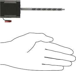
Stepper Motor with Linear Actuation
NEMA 17, 0.002500" Travel Distance, 4" Travel Length


Lead Screw Type | Pass-Through |
Motor Frame Size | NEMA 17 |
Travel Distance per Full Step | 0.0025" |
Travel Length | 4" |
Dynamic Load Capacity | 28 lb. |
Maximum Speed | 3.9 in/sec |
Maximum Current per Phase | 2.6 amp |
Full Step Increment | 1.8° |
Stepper Motor Polarity | Bipolar |
Number of Wire Leads | 4 |
Overall | |
Length | 6.3" |
Width | 1.7" |
Height | 1.7" |
Lead Screw Length | 6" |
Thread Size | 1/4"-16 |
Temperature Range | |
Minimum | 35° F |
Maximum | 130° F |
Accuracy | ±0.0006"/1" |
Actuation Direction | Linear |
Body Shape | Square |
Component | Motors |
Direction of Operation | Clockwise, Counterclockwise |
Duty Cycle | Continuous |
Electrical Connection Type | Hardwire |
Electrical Phase | Two |
Enclosure Material | Aluminum, Steel |
Face Shape | Square |
Inductance per Phase | 1.3 mH |
Insulation | |
Class | B |
Maximum Temperature | 266° F |
Lead Screw Material | 303 Stainless Steel |
Motor Enclosure Type | Totally Enclosed |
Motor Type | Hybrid Stepper |
Mounting Location | Face |
Mounting Position | Any Angle, Horizontal, Vertical |
Number of Thread Starts | 8 |
Power Source | Electric |
Resistance per Phase | 0.9 ohm |
Rotor Inertia | 0.43 oz·in² |
Speed Ratio | 8:1 |
Thread Direction | Right Hand |
Thread Type | Acme |
Threading | Fully Threaded |
Thrust Load Capacity | 28 lbf |
Weight | 0.78 lb. |
Wire Connection | Wire Leads |
Wire Lead Color | Green, Green/White, Red, Red/White |
Wire Lead Gauge (AWG) | 26 |
Wire Lead Length | 12" |
Country of Origin | United States, China, Malaysia |
DFARS Compliance | Specialty Metals COTS-Exempt |
Export Control Classification Number (ECCN) | EAR99 |
REACH Compliance | Not Compliant |
RoHS Compliance | Not Compliant |
Schedule B Number | 850131.6000 |
U.S.–Mexico–Canada Agreement (USMCA) Qualifying | No |
Additional Specifications |
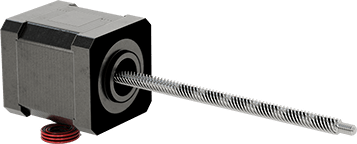
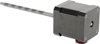
Instead of a shaft, these stepper motors have a lead screw that converts rotational motion to linear motion. Moving in increments smaller than the thickness of a sheet of paper, they're ideal for applications that require fine motion control, such as positioning electrical components on a circuit board. They move in equal steps and hold their position when stationary, so they do not require encoders, sensors, or other position feedback devices. The lead screw is built into the motor, so there are fewer points of failure than systems that use a shaft coupling to connect the lead screw. All are bipolar hybrid stepper motors, which deliver greater torque, precision, and efficiency than other types of stepper motors.
All motors require a controller and drive (not included).
Pass-Through Lead Screw—Pass-through lead screw stepper motors give you the most design versatility because there are two ways to move your load: on the motor body or on the ends of the lead screw. The motor moves when the lead screw is fixed or the lead screw moves when the motor body is fixed.
Travel Distance per Full Step—Travel distance per full step determines the control you have over the motor’s positioning. The smaller the measurement, the finer positioning control you have, but the more steps it will take to go the same distance.
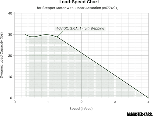
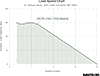
Dynamic Load Capacity—Dynamic load capacity is the maximum load a motor can move. If you increase the speed, the dynamic load capacity decreases. Click on a part number and select "Product Detail" to view the load-speed chart and confirm the motor will work for your application.
Full Step Increment—Full step increment is the rotation of the shaft from one position to the next. A smaller full step increment means the rotor has more teeth, producing smoother and more precise motion. 1.8° is considered standard.
The information in this 3-D model is provided for reference only.