


Filter by
For Use With
Maximum Pressure
Flow Control Type
For Compressed Air Type
Flow Adjustment Mechanism
Export Control Classification Number (ECCN)
DFARS Specialty Metals
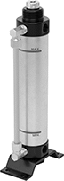
Compressed Air Pressure Boosters
 | 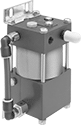 | 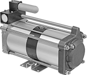 |
Adjustable, 1/4 NPTF Female Supply Inlet and Outlet | Fixed, 1/4 NPT Female Supply Inlet and Outlet | Fixed, 3/8 NPT Female Supply Inlet and Outlet |
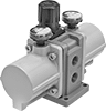
Ensure sufficient pressure to operate air-powered tools and machines. Pressure boosters compress the air supply, which increases air pressure. To maximize performance and service life, install a filter inline before the booster to remove particles down to the maximum particle size. Do not use boosters for tank capacities larger than specified.
Adjustable—Adjustable boosters have an integral regulator so you can fine-tune the output pressure. They come with pressure gauges on the inlet and outlet.
3/8 NPT Female Supply Inlet and Outlet—Boosters with 3/8 NPT female inlet and outlet require compressed air to operate—they have a drive inlet and a pilot inlet that control the booster.
Input to Output Ratio | Pressure, psi | Overall | Mounting Holes | |||||||||||||||
|---|---|---|---|---|---|---|---|---|---|---|---|---|---|---|---|---|---|---|
Pressure | Flow | Input | Output | For Tank Cap. Range, gal. | Max. Particle Size, μm | No. of Inlets | Duty Cycle | Max. Temp. | Lg. | Wd. | Ht. | No. of | Dia. | Mounting Fasteners Included | Each | |||
Adjustable | ||||||||||||||||||
1/4 NPTF Female Supply Inlet and Outlet | ||||||||||||||||||
| 1:2 | 2:1 | 14.5 to 145 | 29 to 290 | 1.32 to 2.64 | 5 | 1 | — | 122° F | 6" | 5" | 4 1/2" | 4 | 0.22" | No | 6828K75 | 0000000 | ||
| 1:4 | 4:1 | 14.5 to 145 | 29 to 290 | 1.32 to 2.64 | 5 | 1 | — | 122° F | 6" | 5" | 4 1/2" | 4 | 0.22" | Yes | 6828K76 | 000000 | ||
Fixed | ||||||||||||||||||
1/4 NPT Female Supply Inlet and Outlet | ||||||||||||||||||
| 1:2 | 2:1 | 10 to 100 | 20 to 200 | 0 to 5 | 40 | 1 | 4 Minutes On, 4 Minutes Off | Not Rated | 7 1/2" | 5 1/4" | 4 1/2" | 4 | 0.28" | No | 3680K41 | 00000000 | ||
| 1:4 | 4:1 | 10 to 100 | 40 to 400 | 0 to 5 | 40 | 1 | 4 Minutes On, 4 Minutes Off | Not Rated | 7 1/2" | 5 1/4" | 4 1/2" | 4 | 0.28" | No | 3680K44 | 00000000 | ||
3/8 NPT Female Supply Inlet and Outlet | ||||||||||||||||||
| 1:2 | 2:1 | 25 to 150 | 30 to 300 | 4 to 60 | 40 | 1 | 30 Minutes On, 30 Minutes Off | 180° F | 17" | 8" | 11" | 4 | 0.38" | No | 9887K11 | 00000000 | ||
| 1:5 | 7:1 | 30 to 870 | 90 to 870 | 1 to 15 | 40 | 2 | 30 Minutes On, 30 Minutes Off | 140° F | 24" | 9" | 9" | 4 | 0.44" | No | 9887K14 | 00000000 | ||
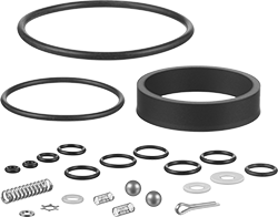 |
Repair Kit |
For Pressure Input to Output Ratio | For Inlet Pipe Size | For Inlet Thread Type | Includes | Each | |||
|---|---|---|---|---|---|---|---|
Air-Drive Repair Kit | |||||||
| 1:2, 1:4 | 1/4 | NPT | Bearing, Nine O-Rings, Spring, Star Washer | 3680K312 | 0000000 | ||
Complete Repair Kit | |||||||
| 1:2 | 1/4 | NPT | Bearing, Cotter Pin, High-Pressure Seal, Star Washer, Thirteen O-Rings, Three Springs, Two Balls, Two Seat Balls | 3680K411 | 000000 | ||
| 1:4 | 1/4 | NPT | Bearing, Cotter Pin, High-Pressure Seal, Star Washer, Thirteen O-Rings, Three Springs, Two Balls, Two Seat Balls | 3680K441 | 000000 | ||
Compressed Air Flow Boosters
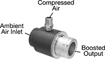 | 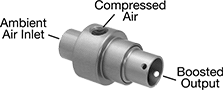 | 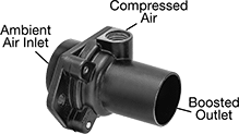 |
Adjustable | Fixed | Fixed with Flange |
Input | Ambient Air Inlet | Outlet | Overall | Flange | Mounting Holes | ||||||||||||||
|---|---|---|---|---|---|---|---|---|---|---|---|---|---|---|---|---|---|---|---|
Flow Input to Output Ratio | Flow Rate @ 90 psi, ft³/min | Pressure, psi | Output Flow Rate @ 90 psi, ft³/min | Max. Particle Size, μm | Connection | For Tube ID | Connection | Outlet Tube OD | Lg. | Wd. | Ht. | Lg. | No. of | Dia. | Mounting Fasteners Included | Each | |||
Adjustable | |||||||||||||||||||
1/8 NPT Male Inlet | |||||||||||||||||||
| 1:6 | 13 | 5 to 150 | 35 to 65 | 20 | Clamp On | 0.75" | Clamp On | 0.75" | 2 9/16" | 1" | — | — | — | — | — | 19075K93 | 000000 | ||
| 1:8 | 13 | 5 to 150 | 37 to 79 | 20 | Clamp On | 0.75" | Clamp On | 0.75" | 2 9/16" | 1 1/8" | — | — | — | — | — | 19075K94 | 00000 | ||
| 1:12 | 25 | 5 to 150 | 155 to 250 | 20 | Clamp On | 1.125" | Clamp On | 1.125" | 2 5/8" | 1 1/2" | — | — | — | — | — | 19075K95 | 000000 | ||
1/4 NPT Male Inlet | |||||||||||||||||||
| 1:15 | 28 | 5 to 150 | 200 to 400 | 20 | Clamp On | 1.5" | Clamp On | 1.5" | 3 1/4" | 2" | — | — | — | — | — | 19075K86 | 000000 | ||
| 1:20 | 29 | 5 to 150 | 330 to 520 | 20 | Clamp On | 2" | Clamp On | 2" | 3 1/4" | 2 1/2" | — | — | — | — | — | 19075K87 | 000000 | ||
| 1:22 | 40 | 5 to 150 | 380 to 840 | 20 | Clamp On | 2.5" | Clamp On | 2.5" | 4 5/8" | 3" | — | — | — | — | — | 19075K88 | 000000 | ||
3/8 NPT Male Inlet | |||||||||||||||||||
| 1:25 | 51 | 5 to 150 | 700 to 1,200 | 20 | Clamp On | 3.5" | Clamp On | 3.5" | 5 1/4" | 4" | — | — | — | — | — | 19075K89 | 000000 | ||
Fixed | |||||||||||||||||||
1/8 NPT Female Inlet | |||||||||||||||||||
| 1:4 | 8 | 10 to 200 | 29.2 | 5 | Clamp On | 0.75" | Clamp On | 0.75" | 2 1/2" | 1 3/8" | — | — | — | — | — | 5205K28 | 000000 | ||
| 1:4 | 8 | 10 to 200 | 29.2 | 5 | Clamp On | 1.33" | Clamp On | 0.75" | 2 1/8" | 1 3/8" | — | — | — | — | — | 5205K27 | 000000 | ||
| 1:4 | 17 | 10 to 200 | 62 | 5 | Clamp On | 1.33" | Clamp On | 0.5" | 2 5/8" | 1 3/8" | — | — | — | — | — | 5205K29 | 000000 | ||
| 1:10 | 6.5 | 5 to 150 | 42 | 20 | Clamp On | 0.98" | Clamp On | 0.73" | 2 3/16" | 2 5/16" | 1.3" | 2.3" | 2 | 0.2" | No | 5571K9 | 000000 | ||
1/4 NPT Female Inlet | |||||||||||||||||||
| 1:15 | 11 | 5 to 150 | 155 | 20 | Clamp On | 1.5" | Clamp On | 1.22" | 2 3/4" | 3" | 1.9" | 3" | 2 | 0.27" | No | 5571K11 | 000000 | ||
3/8 NPT Female Inlet | |||||||||||||||||||
| 1:16 | 21 | 5 to 150 | 325 | 20 | Clamp On | 2.95" | Clamp On | 2" | 3 3/4" | 4 1/8" | 3.2" | 4.1" | 2 | 0.27" | No | 5571K12 | 000000 | ||
1/2 NPT Female Inlet | |||||||||||||||||||
| 1:17 | 42 | 5 to 150 | 615 | 20 | Clamp On | 4.92" | Clamp On | 4" | 7" | 8 1/2" | 5.9" | 8.5" | 2 | 0.53" | No | 5571K13 | 000000 | ||
Air to Hydraulic Power Units
 |
Power a hydraulic cylinder from your air system to avoid the setup, cost, and mess of hydraulic fluid. These converters give you more consistent power than using air power for an air cylinder. However, because air works at a lower pressure than hydraulic fluid, your hydraulic cylinder won’t move loads at its full force. Attach these converters to an air line with a speed controller and solenoid (not included).
Note: These converters are not for use near fire.
Oil Displacement, mm | Overall, mm | Inlet Connection—BSPT | Outlet Connection—BSPT | Drain Connection—BSPT | Mounting Holes | |||||||||||||||
|---|---|---|---|---|---|---|---|---|---|---|---|---|---|---|---|---|---|---|---|---|
Max. | Increments | For Max. Hydraulic Cylinder Stroke Lg., mm | Max. Flow Rate, gpm | Max. Pressure, psi | Cap., gal. | Wd. | Ht. | Pipe Size | Dash Size | Pipe Size | Dash Size | Pipe Size | Dash Size | No. of | Dia., mm | Features | Each | |||
For 40 mm Bore Dia. | ||||||||||||||||||||
| 50 | 50 | 60 | 3.3 | 100 | 0.02 | 107 | 213 | 1/4 | 06 | 1/4 | 06 | — | — | 4 | 7 | Drain Plug | 6476N11 | 000000 | ||
| 100 | 50 | 120 | 3.3 | 100 | 0.03 | 107 | 263 | 1/4 | 06 | 1/4 | 06 | — | — | 4 | 7 | Drain Plug | 6476N12 | 00000 | ||
| 150 | 50 | 180 | 3.3 | 100 | 0.05 | 107 | 313 | 1/4 | 06 | 1/4 | 06 | — | — | 4 | 7 | Drain Plug | 6476N13 | 00000 | ||
| 200 | 50 | 250 | 3.3 | 100 | 0.07 | 107 | 363 | 1/4 | 06 | 1/4 | 06 | — | — | 4 | 7 | Drain Plug | 6476N14 | 00000 | ||
For 63 mm Bore Dia. | ||||||||||||||||||||
| 50 | 50 | 150 | 7.9 | 100 | 0.04 | 104 | 228 | 3/8 | 06 | 3/4 | 12 | 1/4 | 06 | 4 | 11 | Drain Plug | 6476N15 | 00000 | ||
| 100 | 50 | 300 | 7.9 | 100 | 0.08 | 104 | 278 | 3/8 | 06 | 3/4 | 12 | 1/4 | 06 | 4 | 11 | Drain Plug | 6476N16 | 000000 | ||
| 200 | 50 | 600 | 7.9 | 100 | 0.16 | 104 | 378 | 3/8 | 06 | 3/4 | 12 | 1/4 | 06 | 4 | 11 | Drain Plug | 6476N17 | 000000 | ||
| 300 | 50 | 890 | 7.9 | 100 | 0.24 | 104 | 503 | 3/8 | 06 | 3/4 | 12 | 1/4 | 06 | 4 | 11 | Drain Plug | 6476N18 | 000000 | ||
