


Filter by
Product Family
Length
Thread Size
Anchor Type
Screw Size
Ultimate Pull-Out Strength
Material
For Use In
Ultimate Shear Strength
Minimum Installation Depth
Thread Spacing
Export Control Classification Number (ECCN)
DFARS Specialty Metals
Conditions Tested In
Thread Direction
Wedge Anchors for Concrete
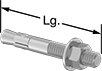 |
Secure junction boxes, safety railings, and structural beams in concrete floors. These anchors have a wedge-shaped base that expands against the hole’s sides, forming a tight grip that withstands high pull-out forces. Since the grip is focused at the base, these anchors are best suited for concrete, which can handle the gripping pressure better than softer block and brick. However, they require holes that match the anchors' diameter exactly to achieve their pull-out strength, making them more difficult to install than sleeve anchors.
To install, drive the anchor through your component into a drilled hole until the washer and nut meet the surface. Then, tighten the nut to expand the anchor base. Remove your component by unfastening the nut, but the anchor itself cannot be removed.
Zinc-Plated Steel—The most common choice for areas with occasional exposure to moisture.
Corrosion-Resistant Galvanized Steel—Combine the strength of steel with the rust resistance of stainless steel. These anchors are an economical alternative to 18-8 stainless steel in wet and outdoor environments, but they’ll corrode or pit when exposed to salt water and chemicals.
Ultimate Strength, lbf | Each | Package | ||||||||||||||
|---|---|---|---|---|---|---|---|---|---|---|---|---|---|---|---|---|
Lg. | Thread Size | Min. Thread Lg. | Min. Installation Dp. | Drill Bit Size | Pull-Out | Shear | Conditions Tested In | Installation Torque, ft·lbf | Certification | Each | Pkg. Qty. | Pkg. | ||||
Zinc-Plated Steel | ||||||||||||||||
1 1/4" Diameter | ||||||||||||||||
| 9" | 1 1/4"-7 | 4 3/4" | 5 5/8" | 1 1/4" | 24,028 | 29,100 | 4,000 psi Concrete | 375 | ICC-ES Listed | 91578A228 | 000000 | 4 | 91578A883 | 000000 | ||
| 12" | 1 1/4"-7 | 7 3/4" | 5 5/8" | 1 1/4" | 24,028 | 29,100 | 4,000 psi Concrete | 375 | ICC-ES Listed | 91578A229 | 00000 | 4 | 91578A885 | 00000 | ||
Corrosion-Resistant Galvanized Steel | ||||||||||||||||
1 1/4" Diameter | ||||||||||||||||
| 9" | 1 1/4"-7 | 2 3/4" | 5 5/8" | 1 1/4" | 28,760 | 47,000 | 4,000 psi Concrete | 400 | — | 97110A805 | 00000 | 4 | 97110A651 | 000000 | ||
| 12" | 1 1/4"-7 | 2 3/4" | 5 5/8" | 1 1/4" | 28,760 | 47,000 | 4,000 psi Concrete | 400 | — | 97110A808 | 00000 | 4 | 97110A652 | 000000 | ||
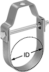
Pivoting Loop Pipe Hangers
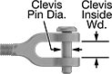
Clevis-to-Eye Turnbuckles—For Lifting
Forged Galvanized Steel Body with Galvanized Steel Fittings
 | ||
Turnbuckles | Jam Nuts | ||||||||||||||||
|---|---|---|---|---|---|---|---|---|---|---|---|---|---|---|---|---|---|
Clevis Pin | |||||||||||||||||
Wt. Cap., lb. | Retracted Lg. | Max. Adjustment | Extended Lg. | Dia. | Closure Method | Clevis Inside Wd. | Eye Shape | Eye ID | Eye Inside Lg. | Thread Size | Specs. Met | Each | Each | ||||
| 15,200 | 32" | 12" | 44" | 1 1/8" | Cotter Pin | 1 27/32" | Oval | 1 13/16" | 3 9/16" | 1 1/4"-7 | ASME B30.26, ASTM F1145 Type 1 | 4129N28 | 0000000 | 30045T811 | 000000 | ||
| 15,200 | 38" | 18" | 56" | 1 1/8" | Cotter Pin | 1 27/32" | Oval | 1 13/16" | 3 9/16" | 1 1/4"-7 | ASME B30.26, ASTM F1145 Type 1 | 4129N29 | 000000 | 30045T811 | 00000 | ||
| 15,200 | 44 1/2" | 24" | 68 1/2" | 1 1/8" | Cotter Pin | 1 27/32" | Oval | 1 13/16" | 3 9/16" | 1 1/4"-7 | ASME B30.26, ASTM F1145 Type 1 | 4129N31 | 000000 | 30045T811 | 00000 | ||
Turnbuckle Bodies—For Lifting
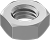
Jam Nuts for Turnbuckles
For Galvanized Steel Turnbuckles
 |
Left- and Right-Hand Thread Direction | |||||||
|---|---|---|---|---|---|---|---|
Thread Size | Wd. | Ht. | Includes | Each | |||
Grade 2 Galvanized Steel | |||||||
| 1 1/4"-7 | 1 7/8" | 23/32" | One Left-Hand Threaded Jam Nut, One Right-Hand Threaded Jam Nut | 30045T811 | 000000 | ||
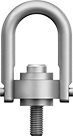
Hoist Rings—For Lifting
 | |
Each | |||||||||||||
|---|---|---|---|---|---|---|---|---|---|---|---|---|---|
Thread Size | Thread Lg. | Inside Wd. | Overall Ht. | Vert. Cap., lb. | Movement | Specs. Met | Certification | Mil. Spec. | 1-9 | 10-Up | |||
Forged Black-Oxide Steel | |||||||||||||
| 1 1/4"-7 | 1 7/8" | 3 1/2" | 11 1/8" | 15,000 | 180° Pivot and 360° Swivel | ASME B30.26 | CE Marked, Mil. Spec. | MIL-STD-1365, MIL-STD-209 | 3070T55 | 0000000 | 0000000 | ||
| 1 1/4"-7 | 1 7/8" | 4" | 11 1/8" | 15,000 | 180° Pivot and 360° Swivel | ASME B30.26 | CE Marked, Mil. Spec. | MIL-STD-1365, MIL-STD-209 | 2994T79 | 000000 | 000000 | ||
| 1 1/4"-7 | 1 15/16" | 3 1/2" | 10 5/8" | 15,000 | 180° Pivot and 360° Swivel | ASME B30.26 | CE Marked, Mil. Spec. | MIL-STD-1365, MIL-STD-209 | 3052T68 | 000000 | 000000 | ||
| 1 1/4"-7 | 2 5/8" | 4" | 11 7/8" | 15,000 | 180° Pivot and 360° Swivel | ASME B30.26 | CE Marked, Mil. Spec. | MIL-STD-1365, MIL-STD-209 | 2994T81 | 000000 | 000000 | ||
Forged Fluorescent Green Powder-Coated Steel—High Visibility | |||||||||||||
| 1 1/4"-7 | 1 7/8" | 4" | 11 1/8" | 15,000 | 180° Pivot and 360° Swivel | ASME B30.26 | CE Marked, Mil. Spec. | MIL-STD-1365, MIL-STD-209 | 4157N21 | 000000 | 000000 | ||
Forged Nickel-Plated Steel | |||||||||||||
| 1 1/4"-7 | 1 7/8" | 4" | 11 1/8" | 15,000 | 180° Pivot and 360° Swivel | ASME B30.26 | CE Marked, Mil. Spec. | MIL-STD-1365, MIL-STD-209 | 3145T87 | 000000 | 000000 | ||
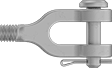
Clevis End Fittings for Turnbuckles—For Lifting
Forged Galvanized Steel
 | |
Clevis Pin | Right-Hand Thread Direction | Left-Hand Thread Direction | |||||||||||
|---|---|---|---|---|---|---|---|---|---|---|---|---|---|
Wt. Cap., lb. | Dia. | Closure Method | Clevis Inside Wd. | Thread Size | Thread Lg. | Overall Lg. | Specs. Met | Each | Each | ||||
| 15,200 | 1 1/8" | Cotter Pin | 1 3/4" | 1 1/4"-7 | 8 3/8" | 15 3/4" | ASME B30.26 | 3001T522 | 0000000 | 3001T722 | 0000000 | ||
| 15,200 | 1 1/8" | Cotter Pin | 1 3/4" | 1 1/4"-7 | 11 3/8" | 18 13/16" | ASME B30.26 | 3001T523 | 000000 | 3001T723 | 000000 | ||
| 15,200 | 1 1/8" | Cotter Pin | 1 3/4" | 1 1/4"-7 | 14 3/8" | 21 13/16" | ASME B30.26 | 3001T524 | 000000 | 3001T724 | 000000 | ||
Clevis-to-Clevis Turnbuckles—For Lifting
Forged Galvanized Steel Body with Forged Galvanized Steel Fittings
| |
Turnbuckles | Jam Nuts | |||||||||||||
|---|---|---|---|---|---|---|---|---|---|---|---|---|---|---|
Clevis Pin | ||||||||||||||
Wt. Cap., lb. | Retracted Lg. | Max. Adjustment | Extended Lg. | Dia. | Closure Method | Clevis Inside Wd. | Thread Size | Specs. Met | Each | Each | ||||
| 15,200 | 31 1/2" | 12" | 43 1/2" | 1 1/8" | Cotter Pin | 1 27/32" | 1 1/4"-7 | ASME B30.26, ASTM F1145 Type 1 | 4498N72 | 0000000 | 30045T811 | 000000 | ||
| 15,200 | 37 1/2" | 18" | 55 1/2" | 1 1/8" | Cotter Pin | 1 27/32" | 1 1/4"-7 | ASME B30.26, ASTM F1145 Type 1 | 4498N73 | 000000 | 30045T811 | 00000 | ||
| 15,200 | 44 1/4" | 24" | 68 1/4" | 1 1/8" | Cotter Pin | 1 27/32" | 1 1/4"-7 | ASME B30.26, ASTM F1145 Type 1 | 4498N74 | 000000 | 30045T811 | 00000 | ||
Eye End Fittings for Turnbuckles—For Lifting
Made of galvanized steel, these fittings have a thick coating for mild corrosion resistance.
Forged Galvanized Steel
Right-Hand Thread Direction | Left-Hand Thread Direction | ||||||||||||
|---|---|---|---|---|---|---|---|---|---|---|---|---|---|
Wt. Cap., lb. | Eye Shape | Eye ID | Eye Inside Lg. | Thread Size | Thread Lg. | Overall Lg. | Specs. Met | Each | Each | ||||
| 15,200 | Oval | 1 13/16" | 3 9/16" | 1 1/4"-7 | 8 3/8" | 16 1/4" | ASME B30.26 | 2999T122 | 0000000 | 2999T322 | 0000000 | ||
| 15,200 | Oval | 1 13/16" | 3 9/16" | 1 1/4"-7 | 11 3/8" | 19 1/4" | ASME B30.26 | 2999T123 | 000000 | 2999T323 | 000000 | ||
| 15,200 | Oval | 1 13/16" | 3 9/16" | 1 1/4"-7 | 14 3/8" | 22 1/4" | ASME B30.26 | 2999T124 | 000000 | 2999T324 | 000000 | ||
Threaded Stud End Fittings for Turnbuckles—Not for Lifting
Threaded Stud-to-Stud Turnbuckles—Not for Lifting
Forged Steel Body with Steel Fittings
Left- and Right-Hand Thread Direction | ||||||||||
|---|---|---|---|---|---|---|---|---|---|---|
Wt. Cap., lb. | Retracted Lg. | Max. Adjustment | Extended Lg. | Retracted Stud Lg. | Thread Size | Specs. Met | Each | |||
| 14,800 | 20" | 6" | 26" | 4 1/2" | 1 1/4"-7 | ASTM F1145 Type 1 | 2996T542 | 0000000 | ||
Turnbuckle Bodies—Not for Lifting
Unthreaded Stub End Fittings for Turnbuckles—Not for Lifting
Unthreaded Stub-to-Stub Turnbuckles—Not for Lifting
Forged Steel Body with 1035 Carbon Steel End Fitting
Forged bodies and components are stronger than cast bodies and components.
Stub | |||||||||||
|---|---|---|---|---|---|---|---|---|---|---|---|
Wt. Cap., lb. | Retracted Lg. | Max. Adjustment | Extended Lg. | Dia. | Lg. | Thread Size | Specs. Met | Each | |||
| 14,800 | 20" | 6" | 26" | 1 1/4" | 4 1/2" | 1 1/4"-7 | ASTM F1145 Type 1 | 2996T371 | 000000 | ||
Removable-Shackle Hoist Rings—For Lifting
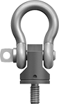 | |
Thread Size | Thread Lg. | Inside Wd. | Overall Ht. | Vert. Cap., lb. | Movement | Specs. Met | Certification | Each | |||
|---|---|---|---|---|---|---|---|---|---|---|---|
Machined Black-Oxide Steel Base with Zinc-Plated Steel Eye | |||||||||||
| 1 1/4"-7 | 1 7/8" | 2 3/4" | 10 1/8" | 15,000 | 180° Pivot and 360° Swivel | ASME B30.26 | CE Marked | 3026T26 | 0000000 | ||
Swivel-Under-Load Hoist Rings—For Lifting
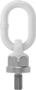 | |
The ball bearing on these hoist rings makes it easy to rotate your load even after it’s suspended. For unbalanced or heavy loads, the base also swivels to compensate for pitch, roll, and sway. Their lifting ring pivots 180° front to back. Ideal for angular lifting, these hoist rings withstand stresses that bend or break eyebolts.
Install the base of these hoist rings flush to your mounting surface. Use a torque wrench to tighten to the recommended torque stamped on the ring.
Note: Capacities listed are for vertical lifting only. As the lift angle changes from vertical, the amount of weight the hoist ring can lift is significantly reduced. For example, when lifting a 1,000 lb. load at a 45° angle, you must choose a hoist ring with a capacity of at least 1,400 lbs. Do not use at an angle less than 30°.
Warning: Never use to lift people or items over people.
Thread Size | Thread Lg. | Inside Wd. | Overall Ht. | Vert. Cap., lb. | Movement | Specs. Met | Certification | Each | |||
|---|---|---|---|---|---|---|---|---|---|---|---|
Forged Yellow Powder-Coated Steel | |||||||||||
| 1 1/4"-7 | 1 7/8" | 2 1/8" | 10 11/16" | 21,160 | 180° Pivot and 360° Swivel | ASME B30.26 | CE Marked | 4137N29 | 0000000 | ||
