

Filter by
Thread Size
Component

Length
Threading
Dynamic Thrust Load Capacity
Thread Direction
Thread Type

Flange Width
Number of Thread Starts
Flange Material
Export Control Classification Number (ECCN)
Ball Screws and Nuts
 |
Internal ball bearings provide smooth low-friction travel in applications that require high speeds, accurate positioning, and repeatable movement. Also known as single-start ball screws and nuts, they have a single thread that runs the length of the screw. They operate with more torque than fast-travel ball screws and nuts. To ensure compatibility, select components that have the same thread direction and size. Ball nuts are furnished with a tube to keep ball bearings in place. Do not remove the tube until you are ready to install the nuts onto the screws.
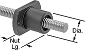
Ball Screws with Flange Ball Nut—Right-Hand Threaded
 | 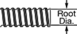 |
Root diameter indicates the diameter the ball screw will be after machining away the threads.
Travel Distance per Turn—Travel distance per turn, also known as screw lead, is the distance a ball nut moves with one revolution of the ball screw.
Ball Screw | Flange Ball Nut, mm | ||||||||||||||||
|---|---|---|---|---|---|---|---|---|---|---|---|---|---|---|---|---|---|
Thread Size | Lg., mm | Root Dia., mm | Tensile Strength, psi | Lg. | Dia. | Lg. Tolerance Type | No. of Thread Starts | Travel Distance per Turn, mm | Accuracy for Travel Distance per Turn | Hardness | Dynamic Thrust Load Cap., lb. | Max. Backlash, mm | Temp. Range, ° F | Each | |||
Carbon Steel Ball Screw with Alloy Steel Flange Ball Nut | |||||||||||||||||
| M6 | 150 | 5.3 | 21,000 | 21 | 13 | Plus | 1 | 1 | ±0.210 mm/300 mm | Rockwell C58 | 150 | 0.05 | 5 to 175 | 6624K66 | 0000000 | ||
| M6 | 250 | 5.3 | 21,000 | 21 | 13 | Plus | 1 | 1 | ±0.210 mm/300 mm | Rockwell C58 | 150 | 0.05 | 5 to 175 | 6638K1 | 000000 | ||
Platform Ball Nuts—Right-Hand Threaded
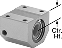 |
Travel Distance per Turn—Travel distance per turn, also known as screw lead, is the distance a ball nut moves with one revolution of the ball screw.
Dry-Running Electric Slides for Stepper Motors
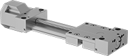 |
With PTFE sleeve bearings and a low-friction ball screw, these slides don’t require the mess and maintenance of lubrication but still give you precise positioning anywhere along the length of their stroke. Because they have sleeve bearings, they have fewer moving parts, so they perform better in dusty and wet environments than slides with ball bearings. They’re also better at handling impact and vibration.
All slides require a stepper motor, driver, and controller (not included) to operate. As part of this system, they move in precise increments, like the head on an inkjet printer. These electric slides work well for automated assemblies and other applications that require fine, repeatable motion control.
Travel Distance per Turn—Travel distance per turn, also known as screw lead, is how far the carriage moves with one rotation of the ball screw.
Dynamic Load Cap. | For Max. Motor | Overall, mm | Carriage | |||||||||||||||||
|---|---|---|---|---|---|---|---|---|---|---|---|---|---|---|---|---|---|---|---|---|
Stroke Lg., mm | Horiz. | Vert. | Static Load Cap., lb. | Max. Speed, mm/s | Travel Distance per Turn, mm | Repeatability, mm | For Shaft Dia. | Speed, rpm | Torque, in·ozf | Lg. | Wd. | Ht. | Lg., mm | Wd., mm | Bearing Type | Base Material | Each | |||
For NEMA 17 Motor Frames | ||||||||||||||||||||
| 100 | Not Rated | Not Rated | 630 | 50 | 2 | -0.1 to 0.1 | 5 mm | 1,500 | 71 | 276 | 74 | 56 | 69 | 73 | Plain | Aluminum | 6650N11 | 0000000 | ||
| 200 | Not Rated | Not Rated | 630 | 50 | 2 | -0.1 to 0.1 | 5 mm | 1,500 | 71 | 376 | 74 | 56 | 69 | 73 | Plain | Aluminum | 6650N13 | 000000 | ||
| 300 | Not Rated | Not Rated | 630 | 50 | 2 | -0.1 to 0.1 | 5 mm | 1,500 | 71 | 476 | 74 | 56 | 69 | 73 | Plain | Aluminum | 6650N15 | 000000 | ||
| 400 | Not Rated | Not Rated | 630 | 50 | 2 | -0.1 to 0.1 | 5 mm | 1,500 | 71 | 576 | 74 | 56 | 69 | 73 | Plain | Aluminum | 6650N17 | 000000 | ||
| 500 | Not Rated | Not Rated | 630 | 50 | 2 | -0.1 to 0.1 | 5 mm | 1,500 | 71 | 676 | 74 | 56 | 69 | 73 | Plain | Aluminum | 6650N19 | 000000 | ||
| 600 | Not Rated | Not Rated | 630 | 50 | 2 | -0.1 to 0.1 | 5 mm | 1,500 | 71 | 776 | 74 | 56 | 69 | 73 | Plain | Aluminum | 6650N22 | 000000 | ||
For NEMA 23 Motor Frames | ||||||||||||||||||||
| 100 | Not Rated | Not Rated | 630 | 50 | 2 | -0.1 to 0.1 | 1/4" | 1,500 | 283 | 277 | 74 | 56 | 69 | 73 | Plain | Aluminum | 6650N12 | 000000 | ||
| 200 | Not Rated | Not Rated | 630 | 50 | 2 | -0.1 to 0.1 | 1/4" | 1,500 | 283 | 377 | 74 | 56 | 69 | 73 | Plain | Aluminum | 6650N14 | 000000 | ||
| 300 | Not Rated | Not Rated | 630 | 50 | 2 | -0.1 to 0.1 | 1/4" | 1,500 | 283 | 477 | 74 | 56 | 69 | 73 | Plain | Aluminum | 6650N16 | 000000 | ||
| 400 | Not Rated | Not Rated | 630 | 50 | 2 | -0.1 to 0.1 | 1/4" | 1,500 | 283 | 577 | 74 | 56 | 69 | 73 | Plain | Aluminum | 6650N18 | 000000 | ||
| 500 | Not Rated | Not Rated | 630 | 50 | 2 | -0.1 to 0.1 | 1/4" | 1,500 | 283 | 677 | 74 | 56 | 69 | 73 | Plain | Aluminum | 6650N21 | 000000 | ||
| 600 | Not Rated | Not Rated | 630 | 50 | 2 | -0.1 to 0.1 | 1/4" | 1,500 | 283 | 777 | 74 | 56 | 69 | 73 | Plain | Aluminum | 6650N23 | 000000 | ||
Clean Room Electric Slides
 |
Slide |
 |
Controller (Included) |
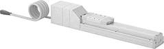
Prevent dust from circulating while precisely positioning parts for drilling, fastening, assembly, and measuring. These slides have a built-in vacuum port to remove fine particles that could damage electronics or contaminate batches in clean rooms. Because they have an integrated stepper motor with an included controller, you can adjust the speed, timing, and positioning. At -0.02 to 0.02 mm, these slides have a repeatability thinner than a single sheet of paper, so the carriage hits the same spot every time. Unlike air-powered actuators, they’ll hold their position even if power fails. They’re also more energy efficient.
For the Manufacturer User Manual, click on a part number and select Product Detail.
Dynamic load capacity is the maximum load slides can move. If you increase the speed, the dynamic load capacity decreases. Use a load-speed chart to confirm which slides will work for your application. Click on a part number and select Product Detail to view the chart.
Maximum Speed—Maximum speed is how fast the slide will move under no-load conditions. If you increase the load, the slide speed will decrease.
Travel Distance per Full Step—Travel distance per full step determines the control you have over the slide’s positioning. The smaller the measurement, the finer positioning control you have.
Travel Distance per Turn—Travel distance per turn, also known as screw lead, is how far the carriage moves with one rotation of the ball screw.
Cords—Use a USB cord (sold separately) and free downloadable software to program the controller.
Slides | Cords | ||||||||||||||||||||
|---|---|---|---|---|---|---|---|---|---|---|---|---|---|---|---|---|---|---|---|---|---|
Dynamic Load Cap., lb. | Travel Distance per, mm | Overall, mm | Carriage | ||||||||||||||||||
Horiz. | Vert. | Max. Speed, mm/s | Full Step | Turn | Repeatability | Lg. | Wd. | Ht. | Lg., mm | Wd., mm | Bearing Type | Base Material | Full Load Current, amp | Voltage, V DC | Clean Room Std. | Each | Each | ||||
200 mm Stroke Length | |||||||||||||||||||||
| 110 | 44 | 250 | 0.08 | 8 | -0.02 mm to 0.02 mm | 541 | 70 | 84 | 122 | 60 | Ball | Aluminum | 5 | 24 | Fed. Std. Class 10, ISO Class 4 | 6833N32 | 000000000 | 6449N17 | 0000000 | ||
| 143 | 50 | 250 | 0.1 | 10 | -0.02 mm to 0.02 mm | 614.5 | 90 | 85.5 | 170 | 74 | Ball | Aluminum | 5 | 24 | Fed. Std. Class 10, ISO Class 4 | 6833N42 | 00000000 | 6449N17 | 000000 | ||
300 mm Stroke Length | |||||||||||||||||||||
| 110 | 44 | 250 | 0.08 | 8 | -0.02 mm to 0.02 mm | 641 | 70 | 84 | 122 | 60 | Ball | Aluminum | 5 | 24 | Fed. Std. Class 10, ISO Class 4 | 6833N33 | 00000000 | 6449N17 | 000000 | ||
400 mm Stroke Length | |||||||||||||||||||||
| 110 | 44 | 250 | 0.08 | 8 | -0.02 mm to 0.02 mm | 741 | 70 | 84 | 122 | 60 | Ball | Aluminum | 5 | 24 | Fed. Std. Class 10, ISO Class 4 | 6833N34 | 00000000 | 6449N17 | 000000 | ||
| 143 | 50 | 250 | 0.1 | 10 | -0.02 mm/0.02 mm | 814.5 | 90 | 85.5 | 170 | 74 | Ball | Aluminum | 5 | 24 | Fed. Std. Class 10, ISO Class 4 | 6833N44 | 00000000 | 6449N17 | 000000 | ||
600 mm Stroke Length | |||||||||||||||||||||
| 143 | 50 | 250 | 0.1 | 10 | -0.02 mm to 0.02 mm | 1,014.5 | 90 | 85.5 | 170 | 74 | Ball | Aluminum | 5 | 24 | Fed. Std. Class 10, ISO Class 4 | 6833N46 | 00000000 | 6449N17 | 000000 | ||
800 mm Stroke Length | |||||||||||||||||||||
| 143 | 50 | 250 | 0.1 | 10 | -0.02 mm to 0.02 mm | 1,214.5 | 90 | 85.5 | 170 | 74 | Ball | Aluminum | 5 | 24 | Fed. Std. Class 10, ISO Class 4 | 6833N48 | 00000000 | 6449N17 | 000000 | ||
Swiveling Locating and Support Buttons
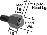 |
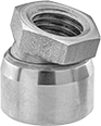
The swiveling tip supports uneven and angled surfaces on workpieces and fixtures. These buttons screw into a threaded hole. Also known as rest buttons.
Head, mm | Thread | |||||||||||||
|---|---|---|---|---|---|---|---|---|---|---|---|---|---|---|
Tip Dia., mm | Lg. | Wd. | Tip-to-Head Lg., mm | Lg., mm | Size | Lg., mm | Range of Motion | Head Lg. Tolerance, mm | Load Cap., lb. | Tip Material | Each | |||
Steel | ||||||||||||||
| 8 | 8 | 10 | 2 | 10 | M6 × 1 mm | 12 | 28° | -0.05 to 0.05 | 2,050 | Stainless Steel | 1417N17 | 000000 | ||
Swivel Pads for Screws and Threaded Studs
 | 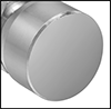 |
Dia., mm | Ht., mm | Load Cap., lb. | Thread Size | Range of Motion | Tip Material | Each | |||
|---|---|---|---|---|---|---|---|---|---|
Steel | |||||||||
| 13 | 16.5 | 520 | M6 | 20° | Steel | 3098N12 | 000000 | ||
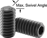
Tight-Clearance Self-Aligning Steel Swivel-Tip Set Screws
Toggle Clamp Holding Screws
Low-Temperature Electric Slides
 |
Slide |
 |
Controller (Included) |
Precisely position parts in conditions as cold as -90° F. These slides contain a grease that lubricates even in low temperatures. With an integrated stepper motor, they’re a complete motion control system for automated assemblies. A controller is included, so you can adjust the speed, timing, and positioning. These slides are often used in actions that require fine, repeatable movement, such as drilling, fastening, assembly, and measuring. The carriage extends the same distance every time within -0.02 to 0.02 mm, a margin thinner than a sheet of paper.
For the Manufacturer User Manual, click on a part number and select Product Detail.
Dynamic load capacity is the maximum load slides can move. If you increase the speed, the dynamic load capacity decreases. Use a load-speed chart to confirm which slides will work for your application. Click on a part number and select Product Detail to view the chart.
Travel Distance per Full Step—Travel distance per full step determines the control you have over the slide’s positioning. The smaller the measurement, the finer positioning control you have.
Travel Distance per Turn—Travel distance per turn, also known as screw lead, is how far the carriage moves with one rotation of the ball screw.
Cords—Use a USB cord (sold separately) and free downloadable software to program the controller for slides that are not 436 mm long.
Slides | Cords | |||||||||||||||||||
|---|---|---|---|---|---|---|---|---|---|---|---|---|---|---|---|---|---|---|---|---|
Dynamic Load Cap., lb. | Travel Distance per, mm | Overall, mm | Carriage | |||||||||||||||||
Horiz. | Vert. | Max. Speed, mm/s | Full Step | Turn | Repeatability, mm | Lg. | Wd. | Ht. | Lg., mm | Wd., mm | Bearing Type | Base Material | Full Load Current, amp | Voltage, V DC | Each | Each | ||||
200 mm Stroke Length | ||||||||||||||||||||
| 88 | 22 | 250 | 0.08 | 16 | -0.02 to 0.02 | 482 | 70 | 79 | 122 | 60 | Roller | Aluminum | 5.2 | 24 | 6449N24 | 000000000 | 6449N17 | 0000000 | ||
400 mm Stroke Length | ||||||||||||||||||||
| 88 | 22 | 250 | 0.08 | 16 | -0.02 to 0.02 | 682 | 70 | 79 | 122 | 60 | Roller | Aluminum | 5.2 | 24 | 6449N25 | 00000000 | 6449N17 | 000000 | ||
600 mm Stroke Length | ||||||||||||||||||||
| 88 | 22 | 250 | 0.08 | 16 | -0.02 to 0.02 | 882 | 70 | 79 | 122 | 60 | Roller | Aluminum | 5.2 | 24 | 6449N26 | 00000000 | 6449N17 | 000000 | ||
Toggle Clamp Holding Screw Tips
 |
Round Push On |
Overall | |||||||
|---|---|---|---|---|---|---|---|
For Holding Screw Thread Size | Dia. | Lg. | Material | Each | |||
Round Push On | |||||||
| 1/4"-20, 1/4"-28, M6 | 7/16" | 7/16" | Rubber | 5147A89 | 00000 | ||
