


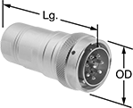
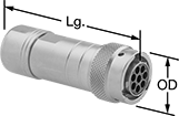
Mil. Spec. Compatible Connectors
 |
 |  |  |  |
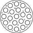
3 Poles (Clockwise) | 4 Poles (Clockwise) | 6 Poles (Clockwise) | 8 Poles (Clockwise) |
 |  |  |  |
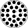
10 Poles (Clockwise) | 12 Poles (Clockwise) | 19 Poles (Clockwise) | 23 Poles (Clockwise) |
 | 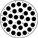 | 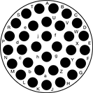 | 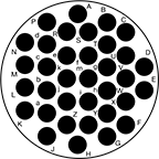 |
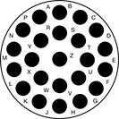
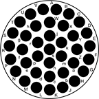
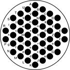
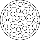
26 Poles (Clockwise) | 28 Poles (Clockwise) | 32 Poles (Clockwise) | 35 Poles (Clockwise) |
 |  | ||
38 Poles (Clockwise) | 48 Poles (Clockwise) |
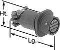
Mil. Spec. Plugs | Crimpers | ||||||||||||||
|---|---|---|---|---|---|---|---|---|---|---|---|---|---|---|---|
No. of Poles | Pole Layout | Voltage | Current, amp | For Wire Ga. | For Cable OD | OD | Lg. | Housing Material | Temp. Range, ° F | Connector Shell Size | Each | Each | |||
| 3 | Clockwise | 250V AC/500V AC/250V DC/500V DC | 13 | 26, 25, 24, 23, 22, 21, 20, 19, 18 | 0.26" to 0.39" | 1" | 2.9" | Nickel-Plated Zinc Alloy | -40 to 220 | 12 | 6168T17 | 000000 | 6168T3 | 000000000 | |
| 4 | Clockwise | 250V AC/500V AC/250V DC/500V DC | 13 | 26, 25, 24, 23, 22, 21, 20, 19, 18 | 0.12" to 0.2" | 0.9" | 2.7" | Nickel-Plated Zinc Alloy | -40 to 220 | 10 | 6168T16 | 00000 | 6168T3 | 00000000 | |
| 6 | Clockwise | 250V AC/250V DC | 7.5 | 30, 29, 28, 27, 26, 25, 24, 23, 22, 21, 20 | 0.12" to 0.2" | 0.9" | 2.7" | Nickel-Plated Zinc Alloy | -40 to 220 | 10 | 6168T11 | 00000 | 6168T3 | 00000000 | |
| 8 | Clockwise | 250V AC/500V AC/250V DC/500V DC | 13 | 26, 25, 24, 23, 22, 21, 20, 19, 18 | 0.26" to 0.39" | 1" | 2.9" | Nickel-Plated Zinc Alloy | -40 to 220 | 12 | 6168T18 | 00000 | 6168T3 | 00000000 | |
| 10 | Clockwise | 250V AC/250V DC | 7.5 | 30, 29, 28, 27, 26, 25, 24, 23, 22, 21, 20 | 0.24" to 0.39" | 1" | 2.9" | Nickel-Plated Zinc Alloy | -40 to 220 | 12 | 6168T12 | 00000 | 6168T3 | 00000000 | |
| 12 | Clockwise | 250V AC/500V AC/250V DC/500V DC | 13 | 18, 17, 16 | 0.26" to 0.39" | 1.2" | 2.9" | Nickel-Plated Zinc Alloy | -40 to 220 | 14 | 6168T19 | 00000 | 6168T3 | 00000000 | |
| 19 | Clockwise | 250V AC/250V DC | 7.5 | 30, 29, 28, 27, 26, 25, 24, 23, 22, 21, 20 | 0.24" to 0.39" | 1.2" | 2.9" | Nickel-Plated Zinc Alloy | -40 to 220 | 14 | 6168T13 | 00000 | 6168T3 | 00000000 | |
| 19 | Clockwise | 250V AC/500V AC/250V DC/500V DC | 13 | 26, 25, 24, 23, 22, 21, 20, 19, 18 | 0.35" to 0.57" | 1.3" | 3.1" | Nickel-Plated Zinc Alloy | -40 to 220 | 16 | 6168T21 | 00000 | 6168T3 | 00000000 | |
| 23 | Clockwise | 250V AC/500V AC/250V DC/500V DC | 13 | 26, 25, 24, 23, 22, 21, 20, 19, 18 | 0.39" to 0.55" | 1.4" | 3.1" | Nickel-Plated Zinc Alloy | -40 to 220 | 18 | 6168T22 | 00000 | 6168T3 | 00000000 | |
| 26 | Clockwise | 250V AC/250V DC | 7.5 | 30, 29, 28, 27, 26, 25, 24, 23, 22, 21, 20 | 0.35" to 0.57" | 1.3" | 3.1" | Nickel-Plated Zinc Alloy | -40 to 220 | 16 | 6168T14 | 00000 | 6168T3 | 00000000 | |
| 28 | Clockwise | 500V AC/500V DC | 3 | 26, 25, 24, 23, 22, 21, 20, 19, 18 | 0.52" to 0.55" | 1.5" | 2.8" | Nickel-Plated Zinc Alloy | -40 to 220 | 20 | 6168T109 | 00000 | 6168T3 | 00000000 | |
| 32 | Clockwise | 250V AC/250V DC | 7.5 | 30, 29, 28, 27, 26, 25, 24, 23, 22, 21, 20 | 0.35" to 0.57" | 1.4" | 3.1" | Nickel-Plated Zinc Alloy | -40 to 220 | 18 | 6168T15 | 00000 | 6168T3 | 00000000 | |
| 35 | Clockwise | 500V AC/500V DC | 13 | 26, 25, 24, 23, 22, 21, 20, 19, 18 | 0.53" to 0.7" | 1.7" | 4" | Nickel-Plated Zinc Alloy | -40 to 220 | 22 | 6168T112 | 000000 | 6168T3 | 00000000 | |
| 38 | Clockwise | 500V AC/500V DC | 13 | 26, 25, 24, 23, 22, 21, 20, 19, 18 | 0.53" to 0.7" | 1.7" | 4" | Nickel-Plated Zinc Alloy | -40 to 220 | 22 | 6168T114 | 000000 | 6168T3 | 00000000 | |
| 48 | Clockwise | 500V AC/500V DC | 3 | 26, 25, 24, 23, 22, 21, 20, 19, 18 | 0.81" to 0.88" | 1.8" | 3.5" | Nickel-Plated Zinc Alloy | -40 to 220 | 24 | 6168T116 | 000000 | 6168T3 | 00000000 | |
 |
 |  |  |  |
3 Poles (Counterclockwise) | 4 Poles (Counterclockwise) | 6 Poles (Counterclockwise) | 8 Poles (Counterclockwise) |
 |  |  | 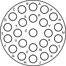 |
10 Poles (Counterclockwise) | 12 Poles (Counterclockwise) | 19 Poles (Counterclockwise) | 23 Poles (Counterclockwise) |
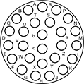 |  | 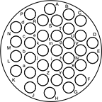 |  |
26 Poles (Counterclockwise) | 28 Poles (Counterclockwise) | 35 Poles (Counterclockwise) | 38 Poles (Counterclockwise) |
 | |||
48 Poles (Counterclockwise) |
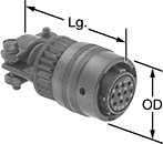
Mil. Spec. Sockets | Crimpers | ||||||||||||||
|---|---|---|---|---|---|---|---|---|---|---|---|---|---|---|---|
No. of Poles | Pole Layout | Voltage | Current, amp | For Wire Ga. | For Cable OD | OD | Lg. | Housing Material | Temp. Range, ° F | Connector Shell Size | Each | Each | |||
| 3 | Counterclockwise | 250V AC/500V AC/250V DC/500V DC | 13 | 26, 25, 24, 23, 22, 21, 20, 19, 18, 17, 16, 15, 14 | 0.26" to 0.39" | 1" | 2.9" | Nickel-Plated Zinc Alloy | -40 to 220 | 12 | 6168T37 | 000000 | 6168T3 | 000000000 | |
| 4 | Counterclockwise | 250V AC/500V AC/250V DC/500V DC | 13 | 26, 25, 24, 23, 22, 21, 20, 19, 18 | 0.12" to 0.2" | 0.9" | 2.7" | Nickel-Plated Zinc Alloy | -40 to 220 | 10 | 6168T36 | 00000 | 6168T3 | 00000000 | |
| 6 | Counterclockwise | 250V AC/250V DC | 7.5 | 30, 29, 28, 27, 26, 25, 24, 23, 22, 21, 20 | 0.12" to 0.2" | 0.9" | 2.7" | Nickel-Plated Zinc Alloy | -40 to 220 | 10 | 6168T31 | 00000 | 6168T3 | 00000000 | |
| 8 | Counterclockwise | 250V AC/500V AC/250V DC/500V DC | 13 | 26, 25, 24, 23, 22, 21, 20, 19, 18 | 0.26" to 0.39" | 1" | 2.9" | Nickel-Plated Zinc Alloy | -40 to 220 | 12 | 6168T38 | 00000 | 6168T3 | 00000000 | |
| 10 | Counterclockwise | 250V AC/250V DC | 7.5 | 30, 29, 28, 27, 26, 25, 24, 23, 22, 21, 20 | 0.24" to 0.39" | 1" | 2.9" | Nickel-Plated Zinc Alloy | -40 to 220 | 12 | 6168T32 | 00000 | 6168T3 | 00000000 | |
| 12 | Counterclockwise | 250V AC/500V AC/250V DC/500V DC | 13 | 26, 25, 24, 23, 22, 21, 20, 19, 18 | 0.26" to 0.39" | 1.2" | 2.9" | Nickel-Plated Zinc Alloy | -40 to 220 | 14 | 6168T39 | 00000 | 6168T3 | 00000000 | |
| 19 | Counterclockwise | 250V AC/250V DC | 7.5 | 30, 29, 28, 27, 26, 25, 24, 23, 22, 21, 20 | 0.24" to 0.39" | 1.2" | 2.9" | Nickel-Plated Zinc Alloy | -40 to 220 | 14 | 6168T43 | 00000 | 6168T3 | 00000000 | |
| 19 | Counterclockwise | 250V AC/500V AC/250V DC/500V DC | 13 | 26, 25, 24, 23, 22, 21, 20, 19, 18 | 0.39" to 0.55" | 1.3" | 3.1" | Nickel-Plated Zinc Alloy | -40 to 220 | 16 | 6168T41 | 00000 | 6168T3 | 00000000 | |
| 23 | Counterclockwise | 250V AC/500V AC/250V DC/500V DC | 13 | 26, 25, 24, 23, 22, 21, 20, 19, 18 | 0.39" to 0.55" | 1.4" | 3.1" | Nickel-Plated Zinc Alloy | -40 to 220 | 18 | 6168T42 | 00000 | 6168T3 | 00000000 | |
| 26 | Counterclockwise | 250V AC/250V DC | 7.5 | 30, 29, 28, 27, 26, 25, 24, 23, 22, 21, 20 | 0.35" to 0.57" | 1.3" | 3.1" | Nickel-Plated Zinc Alloy | -40 to 220 | 16 | 6168T34 | 00000 | 6168T3 | 00000000 | |
| 28 | Counterclockwise | 500V AC/500V DC | 3 | 26, 25, 24, 23, 22, 21, 20, 19, 18 | 0.52" to 0.55" | 1.5" | 2.8" | Nickel-Plated Zinc Alloy | -40 to 220 | 20 | 6168T111 | 00000 | 6168T3 | 00000000 | |
| 35 | Counterclockwise | 500V AC/500V DC | 13 | 26, 25, 24, 23, 22, 21, 20, 19, 18 | 0.53" to 0.7" | 1.7" | 4" | Nickel-Plated Zinc Alloy | -40 to 220 | 22 | 6168T113 | 000000 | 6168T3 | 00000000 | |
| 38 | Counterclockwise | 500V AC/500V DC | 13 | 26, 25, 24, 23, 22, 21, 20, 19, 18 | 0.53" to 0.7" | 1.7" | 4" | Nickel-Plated Zinc Alloy | -40 to 220 | 22 | 6168T115 | 000000 | 6168T3 | 00000000 | |
| 48 | Counterclockwise | 500V AC/500V DC | 3 | 26, 25, 24, 23, 22, 21, 20, 19, 18 | 0.81" to 0.88" | 1.8" | 3.5" | Nickel-Plated Zinc Alloy | -40 to 220 | 24 | 6168T117 | 000000 | 6168T3 | 00000000 | |
 |
| | | | |
3 Poles (Clockwise) | 4 Poles (Clockwise) | 6 Poles (Clockwise) | 8 Poles (Clockwise) | 10 Poles (Clockwise) |
| | | | |
12 Poles (Clockwise) | 19 Poles (Clockwise) | 23 Poles (Clockwise) | 26 Poles (Clockwise) | 32 Poles (Clockwise) |
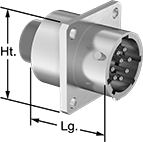
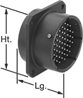
Mil. Spec. Receptacles | Crimpers | |||||||||||||||
|---|---|---|---|---|---|---|---|---|---|---|---|---|---|---|---|---|
No. of Poles | Pole Layout | Voltage | Current, amp | For Wire Ga. | Lg. | Wd. | Ht. | Housing Material | For Panel Cutout Dia. | Temp. Range, ° F | Connector Shell Size | Each | Each | |||
| 3 | Clockwise | 250V AC/500V AC/250V DC/500V DC | 13 | 26, 25, 24, 23, 22, 21, 20, 19, 18 | 1.3" | 1" | 1" | Nickel-Plated Zinc Alloy | 0.81" | -40 to 220 | 12 | 6168T57 | 000000 | 6168T3 | 000000000 | |
| 4 | Clockwise | 250V AC/500V AC/250V DC/500V DC | 13 | 26, 25, 24, 23, 22, 21, 20, 19, 18 | 1.3" | 0.9" | 0.9" | Nickel-Plated Zinc Alloy | 0.72" | -40 to 220 | 10 | 6168T56 | 00000 | 6168T3 | 00000000 | |
| 6 | Clockwise | 250V AC/250V DC | 7.5 | 30, 29, 28, 27, 26, 25, 24, 23, 22, 21, 20 | 1.3" | 0.9" | 0.9" | Nickel-Plated Zinc Alloy | 0.72" | -40 to 220 | 10 | 6168T51 | 00000 | 6168T3 | 00000000 | |
| 8 | Clockwise | 250V AC/500V AC/250V DC/500V DC | 13 | 26, 25, 24, 23, 22, 21, 20, 19, 18 | 1.3" | 1" | 1" | Nickel-Plated Zinc Alloy | 0.81" | -40 to 220 | 12 | 6168T58 | 00000 | 6168T3 | 00000000 | |
| 10 | Clockwise | 250V AC/250V DC | 7.5 | 30, 29, 28, 27, 26, 25, 24, 23, 22, 21, 20 | 1.3" | 1" | 1" | Nickel-Plated Zinc Alloy | 0.81" | -40 to 220 | 12 | 6168T52 | 00000 | 6168T3 | 00000000 | |
| 12 | Clockwise | 250V AC/500V AC/250V DC/500V DC | 13 | 26, 25, 24, 23, 22, 21, 20, 19, 18 | 1.3" | 1.1" | 1.1" | Nickel-Plated Zinc Alloy | 0.91" | -40 to 220 | 14 | 6168T59 | 00000 | 6168T3 | 00000000 | |
| 19 | Clockwise | 250V AC/250V DC | 7.5 | 30, 29, 28, 27, 26, 25, 24, 23, 22, 21, 20 | 1.3" | 1.1" | 1.1" | Nickel-Plated Zinc Alloy | 0.91" | -40 to 220 | 14 | 6168T53 | 00000 | 6168T3 | 00000000 | |
| 19 | Clockwise | 250V AC/500V AC/250V DC/500V DC | 13 | 26, 25, 24, 23, 22, 21, 20, 19, 18 | 1.3" | 1.2" | 1.2" | Nickel-Plated Zinc Alloy | 1" | -40 to 220 | 16 | 6168T62 | 00000 | 6168T3 | 00000000 | |
| 23 | Clockwise | 250V AC/500V AC/250V DC/500V DC | 13 | 26, 25, 24, 23, 22, 21, 20, 19, 18 | 1.3" | 1.3" | 1.3" | Nickel-Plated Zinc Alloy | 1.1" | -40 to 220 | 18 | 6168T63 | 00000 | 6168T3 | 00000000 | |
| 26 | Clockwise | 250V AC/250V DC | 7.5 | 30, 29, 28, 27, 26, 25, 24, 23, 22, 21, 20 | 1.3" | 1.2" | 1.2" | Nickel-Plated Zinc Alloy | 1" | -40 to 220 | 16 | 6168T54 | 00000 | 6168T3 | 00000000 | |
| 32 | Clockwise | 250V AC/250V DC | 7.5 | 30, 29, 28, 27, 26, 25, 24, 23, 22, 21, 20 | 1.3" | 1.3" | 1.3" | Nickel-Plated Zinc Alloy | 1.1" | -40 to 220 | 18 | 6168T55 | 00000 | 6168T3 | 00000000 | |
 |
| | | |
3 Poles (Counterclockwise) | 4 Poles (Counterclockwise) | 6 Poles (Counterclockwise) | 8 Poles (Counterclockwise) |
| | | |
10 Poles (Counterclockwise) | 12 Poles (Counterclockwise) | 19 Poles (Counterclockwise) | 23 Poles (Counterclockwise) |
| |  | |
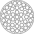
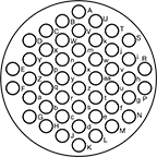
26 Poles (Counterclockwise) | 28 Poles (Counterclockwise) | 32 Poles (Counterclockwise) | 35 Poles (Counterclockwise) |
| | ||
38 Poles (Counterclockwise) | 48 Poles (Counterclockwise) |
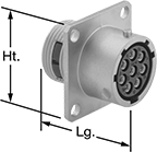
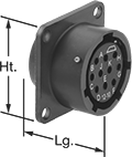
Mil. Spec. Receptacles | Crimpers | |||||||||||||||
|---|---|---|---|---|---|---|---|---|---|---|---|---|---|---|---|---|
No. of Poles | Pole Layout | Voltage | Current, amp | For Wire Ga. | Lg. | Wd. | Ht. | Housing Material | For Panel Cutout Dia. | Temp. Range, ° F | Connector Shell Size | Each | Each | |||
| 3 | Counterclockwise | 250V AC/500V AC/250V DC/500V DC | 13 | 26, 25, 24, 23, 22, 21, 20, 19, 18 | 1.3" | 1" | 1" | Nickel-Plated Zinc Alloy | 0.81" | -40 to 220 | 12 | 6168T77 | 000000 | 6168T3 | 000000000 | |
| 4 | Counterclockwise | 250V AC/500V AC/250V DC/500V DC | 13 | 26, 25, 24, 23, 22, 21, 20, 19, 18 | 1.3" | 0.9" | 0.9" | Nickel-Plated Zinc Alloy | 0.72" | -40 to 220 | 10 | 6168T76 | 00000 | 6168T3 | 00000000 | |
| 6 | Counterclockwise | 250V AC/250V DC | 7.5 | 30, 29, 28, 27, 26, 25, 24, 23, 22, 21, 20 | 1.3" | 0.9" | 0.9" | Nickel-Plated Zinc Alloy | 0.72" | -40 to 220 | 10 | 6168T71 | 00000 | 6168T3 | 00000000 | |
| 8 | Counterclockwise | 250V AC/500V AC/250V DC/500V DC | 13 | 26, 25, 24, 23, 22, 21, 20, 19, 18 | 1.3" | 1" | 1" | Nickel-Plated Zinc Alloy | 0.81" | -40 to 220 | 12 | 6168T78 | 00000 | 6168T3 | 00000000 | |
| 10 | Counterclockwise | 250V AC/250V DC | 7.5 | 30, 29, 28, 27, 26, 25, 24, 23, 22, 21, 20 | 1.3" | 1" | 1" | Nickel-Plated Zinc Alloy | 0.81" | -40 to 220 | 12 | 6168T72 | 00000 | 6168T3 | 00000000 | |
| 12 | Counterclockwise | 250V AC/500V AC/250V DC/500V DC | 13 | 26, 25, 24, 23, 22, 21, 20, 19, 18 | 1.3" | 1.1" | 1.1" | Nickel-Plated Zinc Alloy | 0.91" | -40 to 220 | 14 | 6168T79 | 00000 | 6168T3 | 00000000 | |
| 19 | Counterclockwise | 250V AC/250V DC | 7.5 | 30, 29, 28, 27, 26, 25, 24, 23, 22, 21, 20 | 1.3" | 1.1" | 1.1" | Nickel-Plated Zinc Alloy | 0.91" | -40 to 220 | 14 | 6168T73 | 00000 | 6168T3 | 00000000 | |
| 19 | Counterclockwise | 250V AC/500V AC/250V DC/500V DC | 13 | 26, 25, 24, 23, 22, 21, 20, 19, 18 | 1" | 1.2" | 1.2" | Nickel-Plated Zinc Alloy | 1" | -40 to 220 | 16 | 6168T81 | 00000 | 6168T3 | 00000000 | |
| 23 | Counterclockwise | 250V AC/500V AC/250V DC/500V DC | 13 | 26, 25, 24, 23, 22, 21, 20, 19, 18 | 1.3" | 1.3" | 1.3" | Nickel-Plated Zinc Alloy | 1.1" | -40 to 220 | 18 | 6168T82 | 00000 | 6168T3 | 00000000 | |
| 26 | Counterclockwise | 250V AC/250V DC | 7.5 | 30, 29, 28, 27, 26, 25, 24, 23, 22, 21, 20 | 1.3" | 1.2" | 1.2" | Nickel-Plated Zinc Alloy | 1" | -40 to 220 | 16 | 6168T74 | 00000 | 6168T3 | 00000000 | |
| 28 | Counterclockwise | 500V AC/500V DC | 3 | 26, 25, 24, 23, 22, 21, 20, 19, 18 | 1.3" | 1.4" | 1.4" | Nickel-Plated Zinc Alloy | 1.2" | -40 to 220 | 20 | 6168T102 | 00000 | 6168T3 | 00000000 | |
| 32 | Counterclockwise | 250V AC/250V DC | 7.5 | 30, 29, 28, 27, 26, 25, 24, 23, 22, 21, 20 | 1.3" | 1.3" | 1.3" | Nickel-Plated Zinc Alloy | 1.1" | -40 to 220 | 18 | 6168T75 | 00000 | 6168T3 | 00000000 | |
| 35 | Counterclockwise | 500V AC/500V DC | 13 | 26, 25, 24, 23, 22, 21, 20, 19, 18 | 1.3" | 1.4" | 1.4" | Nickel-Plated Zinc Alloy | 1.2" | -40 to 220 | 22 | 6168T104 | 00000 | 6168T3 | 00000000 | |
| 38 | Counterclockwise | 500V AC/500V DC | 13 | 26, 25, 24, 23, 22, 21, 20, 19, 18 | 1.3" | 1.4" | 1.4" | Nickel-Plated Zinc Alloy | 1.2" | -40 to 220 | 22 | 6168T106 | 00000 | 6168T3 | 00000000 | |
| 48 | Counterclockwise | 500V AC/500V DC | 3 | 26, 25, 24, 23, 22, 21, 20, 19, 18 | 1.5" | 1.7" | 1.7" | Nickel-Plated Zinc Alloy | 1.4" | -40 to 220 | 24 | 6168T108 | 00000 | 6168T3 | 00000000 | |
Mil. Spec. Push-In Connectors
 |
3 Poles | 4 Poles | 6 Poles |
10 Poles | 19 Poles |
No. of Poles | Voltage | Current, amp | For Wire Ga. | For Cable OD | Lg. | Wd. | Ht. | Housing Material | Temp. Range, ° F | Connector Shell Size | Mil. Spec. | Each | ||
|---|---|---|---|---|---|---|---|---|---|---|---|---|---|---|
| 3 | 1,000V AC/1,275V DC | 13 | 20, 19, 18, 17, 16 | 0.31" to 0.43" | 1.9" | 1" | 1" | Cadmium-Plated Aluminum | -65 to 255 | 12 | MIL-DTL-26482, MS3111F12-3P | 6134T61 | 000000 | |
| 4 | 600V AC/850V DC | 7.5 | 24, 23, 22, 21, 20 | 0.13" to 0.24" | 1.9" | 0.8" | 0.8" | Cadmium-Plated Aluminum | -65 to 255 | 8 | MIL-DTL-26482, MS3111F8-4P | 6134T62 | 00000 | |
| 6 | 600V AC/850V DC | 7.5 | 24, 23, 22, 21, 20 | 0.19" to 0.3" | 1.9" | 0.9" | 0.9" | Cadmium-Plated Aluminum | -65 to 255 | 10 | MIL-DTL-26482, MS3111F10-6P | 6134T63 | 00000 | |
| 10 | 600V AC/850V DC | 7.5 | 24, 23, 22, 21, 20 | 0.31" to 0.43" | 1.9" | 1" | 1" | Cadmium-Plated Aluminum | -65 to 255 | 12 | MIL-DTL-26482, MS3111F12-10P | 6134T64 | 00000 | |
| 19 | 600V AC/850V DC | 7.5 | 24, 23, 22, 21, 20 | 0.38" to 0.55" | 1.9" | 1.1" | 1.1" | Cadmium-Plated Aluminum | -65 to 255 | 14 | MIL-DTL-26482, MS3111F14-19P | 6134T66 | 00000 |
| |
15 Poles |
Low-Current | High-Current | |||||||||||||||
|---|---|---|---|---|---|---|---|---|---|---|---|---|---|---|---|---|
No. of Poles | Current, amp | For Wire Gauge | Current, amp | For Wire Gauge | Voltage | For Cable OD | Lg. | Wd. | Ht. | Housing Material | Temp. Range, ° F | Connector Shell Size | Mil. Spec. | Each | ||
| 15 | 7.5 | 24, 23, 22, 21, 20 | 13 | 20, 19, 18, 17, 16 | 600V AC/850V DC | 0.38" to 0.55" | 1.9" | 1.1" | 1.1" | Cadmium-Plated Aluminum | -65 to 255 | 14 | MIL-DTL-26482, MS3111F14-15P | 6134T65 | 000000 | |
 |
3 Poles | 4 Poles | 6 Poles |
 | ||
10 Poles | 19 Poles | 41 Poles |
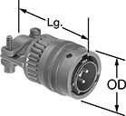
No. of Poles | Voltage | Current, amp | For Wire Ga. | For Cable OD | OD | Lg. | Housing Material | Temp. Range, ° F | Connector Shell Size | Mil. Spec. | Each | ||
|---|---|---|---|---|---|---|---|---|---|---|---|---|---|
| 3 | 1,000V AC/1,275V DC | 13 | 20, 19, 18, 17, 16 | 0.31" to 0.43" | 1" | 1.9" | Cadmium-Plated Aluminum | -65 to 255 | 12 | MIL-DTL-26482, MS3116F12-3P | 6134T41 | 000000 | |
| 4 | 600V AC/850V DC | 7.5 | 24, 23, 22, 21, 20 | 0.13" to 0.24" | 0.8" | 1.9" | Cadmium-Plated Aluminum | -65 to 255 | 8 | MIL-DTL-26482, MS3116F8-4P | 6134T42 | 00000 | |
| 6 | 600V AC/850V DC | 7.5 | 24, 23, 22, 21, 20 | 0.19" to 0.3" | 0.9" | 1.9" | Cadmium-Plated Aluminum | -65 to 255 | 10 | MIL-DTL-26482, MS3116F10-6P | 6134T43 | 00000 | |
| 10 | 600V AC/850V DC | 7.5 | 24, 23, 22, 21, 20 | 0.31" to 0.43" | 1" | 1.9" | Cadmium-Plated Aluminum | -65 to 255 | 12 | MIL-DTL-26482, MS3116F12-10P | 6134T44 | 00000 | |
| 19 | 600V AC/850V DC | 7.5 | 24, 23, 22, 21, 20 | 0.38" to 0.55" | 1.2" | 1.9" | Cadmium-Plated Aluminum | -65 to 255 | 14 | MIL-DTL-26482, MS3116F14-19P | 6134T46 | 00000 | |
| 41 | 600V AC/850V DC | 7.5 | 24, 23, 22, 21, 20 | 0.63" to 0.74" | 1.5" | 2.3" | Cadmium-Plated Aluminum | -65 to 255 | 20 | MIL-DTL-26482, MS3116F20-41P | 6134T47 | 000000 |
| |
15 Poles |
Low-Current | High-Current | ||||||||||||||
|---|---|---|---|---|---|---|---|---|---|---|---|---|---|---|---|
No. of Poles | Current, amp | For Wire Gauge | Current, amp | For Wire Gauge | Voltage | For Cable OD | OD | Lg. | Housing Material | Temp. Range, ° F | Connector Shell Size | Mil. Spec. | Each | ||
| 15 | 7.5 | 24, 23, 22, 21, 20 | 13 | 20, 19, 18, 17, 16 | 600V AC/850V DC | 0.38" to 0.55" | 1.2" | 1.9" | Cadmium-Plated Aluminum | -65 to 255 | 14 | MIL-DTL-26482, MS3116F14-15P | 6134T45 | 000000 | |
 |
3 Poles | 4 Poles | 6 Poles |
10 Poles | 19 Poles |
No. of Poles | Voltage | Current, amp | For Wire Ga. | For Cable OD | Lg. | Wd. | Ht. | Housing Material | Temp. Range, ° F | Connector Shell Size | Mil. Spec. | Each | ||
|---|---|---|---|---|---|---|---|---|---|---|---|---|---|---|
| 3 | 1,000V AC/1,275V DC | 13 | 20, 19, 18, 17, 16 | 0.31" to 0.43" | 1.9" | 1" | 1" | Cadmium-Plated Aluminum | -65 to 255 | 12 | MIL-DTL-26482, MS3111F12-3S | 6134T71 | 000000 | |
| 4 | 600V AC/850V DC | 7.5 | 24, 23, 22, 21, 20 | 0.13" to 0.24" | 1.9" | 0.8" | 0.8" | Cadmium-Plated Aluminum | -65 to 255 | 8 | MIL-DTL-26482, MS3111F8-4S | 6134T72 | 00000 | |
| 6 | 600V AC/850V DC | 7.5 | 24, 23, 22, 21, 20 | 0.19" to 0.3" | 1.9" | 0.9" | 0.9" | Cadmium-Plated Aluminum | -65 to 255 | 10 | MIL-DTL-26482, MS3111F10-6S | 6134T73 | 00000 | |
| 10 | 600V AC/850V DC | 7.5 | 24, 23, 22, 21, 20 | 0.31" to 0.43" | 1.9" | 1" | 1" | Cadmium-Plated Aluminum | -65 to 255 | 12 | MIL-DTL-26482, MS3111F12-10S | 6134T74 | 00000 | |
| 19 | 600V AC/850V DC | 7.5 | 24, 23, 22, 21, 20 | 0.38" to 0.55" | 1.9" | 1.1" | 1.1" | Cadmium-Plated Aluminum | -65 to 255 | 14 | MIL-DTL-26482, MS3111F14-19S | 6134T76 | 00000 |
 |
3 Poles | 4 Poles | 6 Poles |
| ||
10 Poles | 19 Poles | 41 Poles |
No. of Poles | Voltage | Current, amp | For Wire Ga. | For Cable OD | OD | Lg. | Housing Material | Temp. Range, ° F | Connector Shell Size | Mil. Spec. | Each | ||
|---|---|---|---|---|---|---|---|---|---|---|---|---|---|
| 3 | 1,000V AC/1,275V DC | 13 | 20, 19, 18, 17, 16 | 0.31" to 0.43" | 1" | 1.9" | Cadmium-Plated Aluminum | -65 to 255 | 12 | MIL-DTL-26482, MS3116F12-3S | 6134T51 | 000000 | |
| 4 | 600V AC/850V DC | 7.5 | 24, 23, 22, 21, 20 | 0.13" to 0.24" | 0.8" | 1.9" | Cadmium-Plated Aluminum | -65 to 255 | 8 | MIL-DTL-26482, MS3116F8-4S | 6134T52 | 00000 | |
| 6 | 600V AC/850V DC | 7.5 | 24, 23, 22, 21, 20 | 0.19" to 0.3" | 0.9" | 1.9" | Cadmium-Plated Aluminum | -65 to 255 | 10 | MIL-DTL-26482, MS3116F10-6S | 6134T53 | 00000 | |
| 10 | 600V AC/850V DC | 7.5 | 24, 23, 22, 21, 20 | 0.31" to 0.43" | 1" | 1.9" | Cadmium-Plated Aluminum | -65 to 255 | 12 | MIL-DTL-26482, MS3116F12-10S | 6134T54 | 00000 | |
| 19 | 600V AC/850V DC | 7.5 | 24, 23, 22, 21, 20 | 0.38" to 0.55" | 1.2" | 1.9" | Cadmium-Plated Aluminum | -65 to 255 | 14 | MIL-DTL-26482, MS3116F14-19S | 6134T56 | 00000 | |
| 41 | 600V AC/850V DC | 7.5 | 24, 23, 22, 21, 20 | 0.63" to 0.74" | 1.5" | 2.3" | Cadmium-Plated Aluminum | -65 to 255 | 20 | MIL-DTL-26482, MS3116F20-41S | 6134T57 | 000000 |
| |
15 Poles |
Low-Current | High-Current | ||||||||||||||
|---|---|---|---|---|---|---|---|---|---|---|---|---|---|---|---|
No. of Poles | Current, amp | For Wire Gauge | Current, amp | For Wire Gauge | Voltage | For Cable OD | OD | Lg. | Housing Material | Temp. Range, ° F | Connector Shell Size | Mil. Spec. | Each | ||
| 15 | 7.5 | 24, 23, 22, 21, 20 | 13 | 20, 19, 18, 17, 16 | 600V AC/850V DC | 0.38" to 0.55" | 1.2" | 1.9" | Cadmium-Plated Aluminum | -65 to 255 | 14 | MIL-DTL-26482, MS3116F14-15S | 6134T55 | 000000 | |
 |
3 Poles | 4 Poles | 6 Poles |
| ||
10 Poles | 19 Poles | 41 Poles |
No. of Poles | Voltage | Current, amp | For Wire Ga. | Lg. | Wd. | Ht. | Housing Material | For Panel Cutout Dia. | Temp. Range, ° F | Connector Shell Size | Mil. Spec. | Each | ||
|---|---|---|---|---|---|---|---|---|---|---|---|---|---|---|
| 3 | 1,000V AC/1,275V DC | 13 | 20, 19, 18, 17, 16 | 0.8" | 1" | 1" | Cadmium-Plated Aluminum | 0.7" | -65 to 255 | 12 | MIL-DTL-26482, MS3112E12-3P | 6134T21 | 000000 | |
| 4 | 600V AC/850V DC | 7.5 | 24, 23, 22, 21, 20 | 0.8" | 0.8" | 0.8" | Cadmium-Plated Aluminum | 0.45" | -65 to 255 | 8 | MIL-DTL-26482, MS3112E8-4P | 6134T22 | 00000 | |
| 6 | 600V AC/850V DC | 7.5 | 24, 23, 22, 21, 20 | 0.8" | 1" | 1" | Cadmium-Plated Aluminum | 0.57" | -65 to 255 | 10 | MIL-DTL-26482, MS3112E10-6P | 6134T23 | 00000 | |
| 10 | 600V AC/850V DC | 7.5 | 24, 23, 22, 21, 20 | 0.8" | 1" | 1" | Cadmium-Plated Aluminum | 0.7" | -65 to 255 | 12 | MIL-DTL-26482, MS3112E12-10P | 6134T24 | 00000 | |
| 19 | 600V AC/850V DC | 7.5 | 24, 23, 22, 21, 20 | 0.8" | 1.1" | 1.1" | Cadmium-Plated Aluminum | 0.82" | -65 to 255 | 14 | MIL-DTL-26482, MS3112E14-19P | 6134T26 | 00000 | |
| 41 | 600V AC/850V DC | 7.5 | 24, 23, 22, 21, 20 | 1.1" | 1.4" | 1.4" | Cadmium-Plated Aluminum | 1.2" | -65 to 255 | 20 | MIL-DTL-26482, MS3112E20-41P | 6134T27 | 00000 |
| |
15 Poles |
Low-Current | High-Current | |||||||||||||||
|---|---|---|---|---|---|---|---|---|---|---|---|---|---|---|---|---|
No. of Poles | Current, amp | For Wire Gauge | Current, amp | For Wire Gauge | Voltage | Lg. | Wd. | Ht. | Housing Material | For Panel Cutout Dia. | Temp. Range, ° F | Connector Shell Size | Mil. Spec. | Each | ||
| 15 | 7.5 | 24, 23, 22, 21, 20 | 13 | 20, 19, 18, 17, 16 | 600V AC/850V DC | 0.8" | 1.1" | 1.1" | Cadmium-Plated Aluminum | 0.82" | -65 to 255 | 14 | MIL-DTL-26482, MS3112E14-15P | 6134T25 | 000000 | |
 |
3 Poles | 4 Poles | 6 Poles |
| ||
10 Poles | 19 Poles | 41 Poles |
No. of Poles | Voltage | Current, amp | For Wire Ga. | Lg. | Wd. | Ht. | Housing Material | For Panel Cutout Dia. | Temp. Range, ° F | Connector Shell Size | Mil. Spec. | Each | ||
|---|---|---|---|---|---|---|---|---|---|---|---|---|---|---|
| 3 | 1,000V AC/1,275V DC | 13 | 20, 19, 18, 17, 16 | 0.8" | 1" | 1" | Cadmium-Plated Aluminum | 0.86" | -65 to 255 | 12 | MIL-DTL-26482, MS3112E12-3S | 6134T31 | 000000 | |
| 4 | 600V AC/850V DC | 7.5 | 24, 23, 22, 21, 20 | 0.8" | 0.8" | 0.8" | Cadmium-Plated Aluminum | 0.61" | -65 to 255 | 8 | MIL-DTL-26482, MS3112E8-4S | 6134T32 | 00000 | |
| 6 | 600V AC/850V DC | 7.5 | 24, 23, 22, 21, 20 | 0.8" | 1" | 1" | Cadmium-Plated Aluminum | 0.74" | -65 to 255 | 10 | MIL-DTL-26482, MS3112E10-6S | 6134T33 | 00000 | |
| 10 | 600V AC/850V DC | 7.5 | 24, 23, 22, 21, 20 | 0.8" | 1" | 1" | Cadmium-Plated Aluminum | 0.86" | -65 to 255 | 12 | MIL-DTL-26482, MS3112E12-10S | 6134T34 | 00000 | |
| 19 | 600V AC/850V DC | 7.5 | 24, 23, 22, 21, 20 | 0.8" | 1.1" | 1.1" | Cadmium-Plated Aluminum | 0.99" | -65 to 255 | 14 | MIL-DTL-26482, MS3112E14-19S | 6134T36 | 00000 | |
| 41 | 600V AC/850V DC | 7.5 | 24, 23, 22, 21, 20 | 0.89" | 1.4" | 1.4" | Cadmium-Plated Aluminum | 1.36" | -65 to 255 | 20 | MIL-DTL-26482, MS3112E20-41S | 6134T37 | 000000 |
| |
15 Poles |
Low-Current | High-Current | |||||||||||||||
|---|---|---|---|---|---|---|---|---|---|---|---|---|---|---|---|---|
No. of Poles | Current, amp | For Wire Gauge | Current, amp | For Wire Gauge | Voltage | Lg. | Wd. | Ht. | Housing Material | For Panel Cutout Dia. | Temp. Range, ° F | Connector Shell Size | Mil. Spec. | Each | ||
| 15 | 7.5 | 24, 23, 22, 21, 20 | 13 | 20, 19, 18, 17, 16 | 600V AC/850V DC | 0.8" | 1.1" | 1.1" | Cadmium-Plated Aluminum | 0.99" | -65 to 255 | 14 | MIL-DTL-26482, MS3112E14-15S | 6134T35 | 000000 | |
Thermocouple and RTD Bayonet Adapters
 |
For Max. Probe Dia. | Lg. | Body Material | Each | |||
|---|---|---|---|---|---|---|
1/8 NPT Male | ||||||
| 9/32" | 7/8" | Stainless Steel | 2752N11 | 00000 | ||
| 9/32" | 1 1/4" | Stainless Steel | 2752N13 | 0000 | ||
| 9/32" | 1 1/2" | Stainless Steel | 2752N14 | 0000 | ||
| 9/32" | 2" | Stainless Steel | 2752N15 | 0000 | ||
| 9/32" | 2 1/4" | Stainless Steel | 2752N16 | 0000 | ||
| 9/32" | 2 1/2" | Stainless Steel | 2752N17 | 0000 | ||
| 9/32" | 3 1/2" | Stainless Steel | 2752N18 | 00000 | ||
3/8"-24 UNF Male | ||||||
| 9/32" | 7/8" | Stainless Steel | 3860K11 | 00000 | ||
| 9/32" | 1 1/2" | Stainless Steel | 3860K12 | 00000 | ||
| 9/32" | 1 3/4" | Stainless Steel | 3860K73 | 00000 | ||
| 9/32" | 2 1/2" | Stainless Steel | 3860K13 | 00000 | ||
| 9/32" | 3 1/2" | Stainless Steel | 3860K14 | 00000 | ||
 |
Band | |||||||||||
|---|---|---|---|---|---|---|---|---|---|---|---|
Clamp ID Range | For Max. Probe Dia. | Lg. | Wd. | Thk. | Drive Style | Hex Size | Body Material | Each | |||
| 1/2" to 7/8" | 9/32" | 1 3/8" | 1/2" | 0.023" | Slotted, External Hex | 5/16" | Stainless Steel | 2752N21 | 000000 | ||
| 7/8" to 1 1/2" | 9/32" | 1 3/8" | 1/2" | 0.023" | Slotted, External Hex | 5/16" | Stainless Steel | 2752N22 | 00000 | ||
| 1 5/16" to 2 1/4" | 9/32" | 1 3/8" | 1/2" | 0.023" | Slotted, External Hex | 5/16" | Stainless Steel | 2752N23 | 00000 | ||
| 2 1/4" to 3 5/16" | 9/32" | 1 3/8" | 1/2" | 0.023" | Slotted, External Hex | 5/16" | Stainless Steel | 2752N24 | 00000 | ||
| 3 5/16" to 4 1/4" | 9/32" | 1 3/8" | 1/2" | 0.023" | Slotted, External Hex | 5/16" | Stainless Steel | 2752N25 | 00000 | ||
| 4 5/16" to 5 1/4" | 9/32" | 1 3/8" | 1/2" | 0.023" | Slotted, External Hex | 5/16" | Stainless Steel | 2752N26 | 00000 | ||
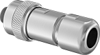
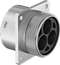
Vibration-Resistant High-Current Ecomate Connectors
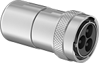 |  |  |
Front | Back | 3 Poles |
No. of Poles | Shielding | Voltage | Current, amp | For Wire Ga. | For Cable OD | OD | Lg. | Housing Material | Temp. Range, ° F | Connector Shell Size | Flammability Rating | Each | ||
|---|---|---|---|---|---|---|---|---|---|---|---|---|---|---|
| 3 | Shielded | 630V AC/630V DC | 86 | 8 | 0.53" to 0.55" | 1.5" | 2.8" | Nickel-Plated Zinc Alloy | -40 to 255 | 20 | UL 94 V-0 | 4577N25 | 000000 |
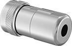
 |  |
Front | Back |
No. of Poles | Shielding | Voltage | Current, amp | For Wire Ga. | For Cable OD | OD | Lg. | Housing Material | Temp. Range, ° F | Connector Shell Size | Flammability Rating | Each | ||
|---|---|---|---|---|---|---|---|---|---|---|---|---|---|---|
| 1 | Shielded | 630V AC/630V DC | 86 | 8 | 0.37" to 0.49" | 1" | 2.7" | Nickel-Plated Zinc Alloy | -40 to 255 | 12 | UL 94 V-0 | 4577N13 | 000000 | |
| 1 | Shielded | 630V AC/630V DC | 120 | 4 | 0.37" to 0.49" | 1.1" | 3.4" | Nickel-Plated Zinc Alloy | -40 to 255 | 14 | UL 94 V-0 | 4577N16 | 00000 | |
| 1 | Shielded | 630V AC/630V DC | 130 | 2 | 0.53" to 0.59" | 1.2" | 3.6" | Nickel-Plated Zinc Alloy | -40 to 255 | 16 | UL 94 V-0 | 4577N19 | 00000 | |
| 1 | Shielded | 630V AC/630V DC | 180 | 1/0 | 0.64" to 0.66" | 1.5" | 3.5" | Nickel-Plated Zinc Alloy | -40 to 255 | 20 | UL 94 V-0 | 4577N23 | 000000 |
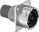 |  |
Front | Back |
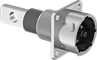
Mounting | |||||||||||||||||
|---|---|---|---|---|---|---|---|---|---|---|---|---|---|---|---|---|---|
No. of Poles | Voltage | Current, amp | For Wire Ga. | For Panel Cutout Dia. | Lg. | Wd. | Ht. | Housing Material | Temp. Range, ° F | Connector Shell Size | Fasteners Included | No. of Holes | Hole Dia. | Flammability Rating | Each | ||
| 1 | 630V AC/630V DC | 86 | 8 | 0.71" | 1.5" | 1" | 1" | Nickel-Plated Zinc Alloy | -40 to 255 | 12 | No | 4 | 0.12" | UL 94 V-0 | 4577N11 | 000000 | |
| 1 | 630V AC/630V DC | 120 | 4 | 0.97" | 1.8" | 1.1" | 1.1" | Nickel-Plated Zinc Alloy | -40 to 255 | 14 | No | 4 | 0.12" | UL 94 V-0 | 4577N14 | 00000 | |
| 1 | 630V AC/630V DC | 130 | 2 | 1.08" | 2" | 1.2" | 1.2" | Nickel-Plated Zinc Alloy | -40 to 255 | 16 | No | 4 | 0.12" | UL 94 V-0 | 4577N17 | 00000 | |
| 1 | 630V AC/630V DC | 180 | 1/0 | 1.36" | 2.1" | 1.4" | 1.4" | Nickel-Plated Zinc Alloy | -40 to 255 | 20 | No | 4 | 0.16" | UL 94 V-0 | 4577N21 | 00000 | |
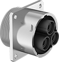 |  | |
Front | Back | 3 Poles |
Mounting | |||||||||||||||||
|---|---|---|---|---|---|---|---|---|---|---|---|---|---|---|---|---|---|
No. of Poles | Voltage | Current, amp | For Wire Ga. | For Panel Cutout Dia. | Lg. | Wd. | Ht. | Housing Material | Temp. Range, ° F | Connector Shell Size | Fasteners Included | No. of Holes | Hole Dia. | Flammability Rating | Each | ||
| 3 | 630V AC/630V DC | 86 | 8 | 1.36" | 1.3" | 1.4" | 1.4" | Nickel-Plated Zinc Alloy | -40 to 255 | 20 | No | 4 | 0.16" | UL 94 V-0 | 4577N24 | 000000 | |
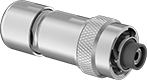
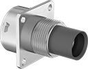
 | 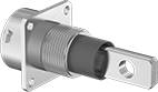 |
Front | Back |
Mounting | |||||||||||||||||
|---|---|---|---|---|---|---|---|---|---|---|---|---|---|---|---|---|---|
No. of Poles | Voltage | Current, amp | For Wire Ga. | For Panel Cutout Dia. | Lg. | Wd. | Ht. | Housing Material | Temp. Range, ° F | Connector Shell Size | Fasteners Included | No. of Holes | Hole Dia. | Flammability Rating | Each | ||
| 1 | 630V AC/630V DC | 86 | 8 | 0.71" | 2.2" | 1" | 1" | Nickel-Plated Zinc Alloy | -40 to 255 | 12 | No | 4 | 0.12" | UL 94 V-0 | 4577N12 | 000000 | |
| 1 | 630V AC/630V DC | 120 | 4 | 0.97" | 2" | 1.1" | 1.1" | Nickel-Plated Zinc Alloy | -40 to 255 | 14 | No | 4 | 0.12" | UL 94 V-0 | 4577N15 | 00000 | |
| 1 | 630V AC/630V DC | 180 | 1/0 | 1.08" | 2.4" | 1.2" | 1.2" | Nickel-Plated Zinc Alloy | -40 to 255 | 16 | No | 4 | 0.12" | UL 94 V-0 | 4577N18 | 00000 | |
| 1 | 630V AC/630V DC | 300 | 1/0 | 1.36" | 2.8" | 1.4" | 1.4" | Nickel-Plated Zinc Alloy | -40 to 255 | 20 | No | 4 | 0.16" | UL 94 V-0 | 4577N22 | 00000 | |
Thermocouple Connector Adapters
Material | ||||||||||
|---|---|---|---|---|---|---|---|---|---|---|
Thermocouple Type | Max. Temp., ° F | Color | Pin Lg. | Distance Between Pins | Body | Contact | Each | |||
Female Round-Pin Thermocouple Connector × Male Flat-Pin Mini Thermocouple Connector | ||||||||||
| B | 400 | White | 7/16" | 0.438" | Plastic | Platinum | 3869K221 | 000000 | ||
| C | 400 | Brown | 7/16" | 0.438" | Plastic | Tungsten | 3869K222 | 00000 | ||
| E | 400 | Purple | 7/16" | 0.438" | Plastic | Nickel | 3869K216 | 00000 | ||
| J | 400 | Black | 7/16" | 0.438" | Plastic | Iron | 3869K69 | 00000 | ||
| K | 400 | Yellow | 7/16" | 0.438" | Plastic | Nickel | 3869K71 | 00000 | ||
| N | 400 | Orange | 7/16" | 0.438" | Plastic | Nickel | 3869K215 | 00000 | ||
| R | 400 | Green | 7/16" | 0.438" | Plastic | Platinum | 3869K217 | 00000 | ||
| S | 400 | Green | 7/16" | 0.438" | Plastic | Platinum | 3869K218 | 00000 | ||
| T | 400 | Blue | 7/16" | 0.438" | Plastic | Copper | 3869K214 | 00000 | ||
| U | 400 | White | 7/16" | 0.438" | Plastic | Copper | 3869K219 | 00000 | ||
