


Filter by
Screw Size

Material
Offset Length


Angle
Thickness
Number of Mounting Holes
Weight Capacity
DFARS Specialty Metals
Export Control Classification Number (ECCN)
RoHS
Color

Appearance
Finish
Mounting Screw Size
Mounting Location

Corner Radius

Flat-Surface Machine Brackets
 |
Used for mounting applications on machines and automated equipment, these brackets are made to meet tight dimensional tolerances.
Lg., mm | Mounting | |||||||||||||
|---|---|---|---|---|---|---|---|---|---|---|---|---|---|---|
(A) | (C) | Lg. Tolerance, mm | Thk., mm | Thk. Tolerance, mm | Flatness Tolerance, mm | Wt. Cap. | Mount Type | Fasteners Included | No. of Slots | For Screw Size | Each | |||
Dull 6061 Aluminum | ||||||||||||||
| 75 | 20 | -0.5 to 0.5 | 3 | -0.2 to 0.2 | 0.38 | Not Rated | Screw On | No | 2 | M8 | 2312N42 | 00000 | ||
Dull 316 Stainless Steel | ||||||||||||||
| 75 | 20 | -0.5 to 0.5 | 3 | -0.2 to 0.2 | 0.38 | Not Rated | Screw On | No | 2 | M8 | 2312N25 | 0000 | ||
Offset-Surface Machine Brackets
 |
With tight dimensional tolerances, these brackets are good for mounting applications on machines and automated equipment.
Lg., mm | Mounting | ||||||||||||||||||
|---|---|---|---|---|---|---|---|---|---|---|---|---|---|---|---|---|---|---|---|
(A) | (B) | (C) | Offset | Lg. Tolerance, mm | Thk., mm | Thk. Tolerance, mm | Angle | Angle Tolerance | Corner Radius, mm | Flatness Tolerance, mm | Wt. Cap. | Mount Type | Fasteners Included | No. of Slots | For Screw Size | Each | |||
Dull 316 Stainless Steel | |||||||||||||||||||
| 50 | 65 | 60 | 40 | -0.5 to 0.5 | 3 | -0.2 to 0.2 | 90° | -1° to 1° | 3.2 | 0.38 | Not Rated | Screw On | No | 4 | M8 | 2314N18 | 000000 | ||
Modular Mini Chain Belt Conveyors
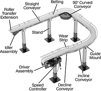 |
Build a mini conveyor in any shape you need. These conveyors have curved, straight, incline, and decline runs that you can quickly join together with the included brackets. They're often used in areas with limited floor space and applications that require frequent layout changes. To customize your conveyor, add on components, such as package stops and merge guides, with the built-in T-slots on the side. These conveyors come with guides installed.
You'll need a drive assembly, an idler assembly, and a belt to complete your conveyor. To determine the belt length you need, multiply your conveyor’s length by 2.1. If you need a belt longer than what’s available, you can connect multiple together. Use a belt installation tool to pull out the pin, then line up two ends and push the pin in with the tool to connect them. You can also shorten a belt using the same tool.
Maximum run length is 70 ft. with two 90° curves. Adding more curved conveyors will reduce the run length.
Guide Rail Spacers
 |
Wd. | For T-Slot Wd., mm | Ht. | Material | Mounting Fasteners Included | For Screw Size | Pkg. Qty. | Pkg. | |||
|---|---|---|---|---|---|---|---|---|---|---|
| 1/4" | 11 | 1 1/8" | Aluminum | No | M8 | 10 | 4766N114 | 000000 | ||
Heavy Duty Ball-Grip Positioning Arms
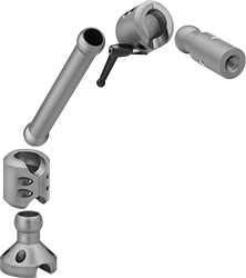 |
Arm Built with Base, Two Straight Connectors, Straight Link, Locking Handle, and Sensor Mount |
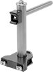
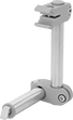
With strength for higher load capacities than other ball-grip positioning arms, these arms have a heavy duty construction. Ball-and-socket connections allow 360° positioning. The base, connectors, and links are hollow for routing wires, cables, and small hoses. Select a base, connectors, link, and plate or mount to build a complete arm. Capacities are based on an assembled arm that is 1 foot long.
Vacuum Lifter Mounts
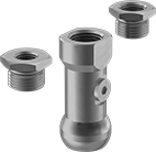 |
Air Connection | |||||||||||||
|---|---|---|---|---|---|---|---|---|---|---|---|---|---|
Dia. | Lg. | Max. Load Cap., lb. | Material | Color | Pipe Size | Thread Type | Gender | Mounting Hole Pipe Size (Mounting Hole Thread Type) | Mounting Hole Screw Size | Each | |||
Rotate, Tilt, Side to Side, In/Out | |||||||||||||
| 1 1/4" | 3 1/16" | 30 | Anodized Aluminum | Blue | 1/2 | BSPP | Female | 1/4 (BSPP); 3/8 (BSPP); 1/2 (BSPP) | M8 | 1530N222 | 0000000 | ||
Tie-Down Rings
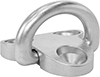 |
Style H |
These rings pivot to secure loads in various directions.
Warning: Never use for lifting applications.
316 Stainless Steel—316 stainless steel rings have excellent resistance to salt water and chemicals.
Ring | Base | Mounting Holes | Each | ||||||||||||||||
|---|---|---|---|---|---|---|---|---|---|---|---|---|---|---|---|---|---|---|---|
Style | Wt. Cap., lb. | Inner Wd. | Ht. | Thk. | Style | Lg. | Wd. | Material | Mounting Fasteners Included | No. of | Dia. | Ctr.-to-Ctr. Wd. | Ctr.-to-Ctr. Lg. | For Mounting Screw Size | 1-99 | 100-Up | |||
316 Stainless Steel | |||||||||||||||||||
| H | 5,290 | 1 3/8" | 1 3/8" | 5/16" | D-Ring | 2 3/16" | 2 1/4" | 316 Stainless Steel | No | 3 | 5/16" | 1 3/8" | 1 3/8" | M8 | 33815T12 | 000000 | 000000 | ||
Tilt Down Drawer Slides
 |
 |
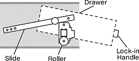
Access items stored overhead or at the back of deep drawers. These slides tilt a drawer downward when it's pulled out, bringing items closer to you. Unlike standard drawer slides, when your drawer hits the end of these slides, it rotates to angle the drawer down. Made from aluminum, these slides are lightweight and corrosion resistant.
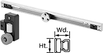
Each pair of slides includes tracks, roller wheel assemblies, bumpers, end stops, and caps. Mount the tracks to the sides of drawer openings in cabinets. The roller wheel assembly mounts at the front of the cabinet to guide and support the base of the drawer. Adjust the angle of the track and the position of the end stops and bumpers to determine how far the drawer will drop down. You can also cut the tracks to match the length of your cabinet.
Roller Assembly | Mounting | ||||||||||||||
|---|---|---|---|---|---|---|---|---|---|---|---|---|---|---|---|
Lg. | For Max. Drawer Wd. | Wd. | Ht. | Wt. Cap. per Pair, lb. | Roller Type | Lg. | Wd. | Ht. | Fasteners Included | Screw Size | Extension | Pair | |||
Aluminum | |||||||||||||||
Without Release | |||||||||||||||
| 24" | 40" | 1 3/4" | 1 9/16" | 140 | Roller Bearing | 4 5/16" | 3 1/8" | 6 3/8" | No | M8 | Full | 7042N11 | 0000000 | ||
| 40" | 40" | 1 3/4" | 1 9/16" | 140 | Roller Bearing | 4 5/16" | 3 1/8" | 6 3/8" | No | M8 | Full | 7042N12 | 000000 | ||
 |
Add a lock-in handle to hold your drawer in place when it's closed. Often used in utility trucks and emergency vehicles, it keeps drawers from sliding open when you’re in motion. The handle and push button mount to the front of the drawer, so you can disengage the lock and pull the drawer open at the same time. Locking pins mount inside the drawer and extend out on each side to latch onto the roller assembly. You can cut them to match the width of your drawer.
Mounting | Handle | Grip | Push Button | |||||||||||||
|---|---|---|---|---|---|---|---|---|---|---|---|---|---|---|---|---|
No. of Holes | Hole Ctr.-to-Ctr. Wd. | Hole Ctr.-to-Ctr. Ht. | Fasteners Included | Screw Size | Material | Style | Color | Ht. | Thick. | Projection | Locking Mechanism | Material | Color | Each | ||
| 4 | 12 5/8" | 13/16" | No | M5 | Aluminum | Pull | Black | 1 9/16" | 3/8" | 1 9/16" | Push Button | Plastic | Yellow | 7042N14 | 0000000 | |
