



























Filter by


System of Measurement
Screw Size

Length
Weight Capacity
Mounting Hole Style
Mounting Location


DFARS Specialty Metals
Appearance
Export Control Classification Number (ECCN)
For Use On
Corner Brackets
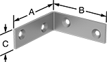 | 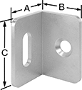 | 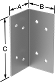 |
Style 2 | Style 6 | Style 10 |
Lg. | Each | |||||||||||||||
|---|---|---|---|---|---|---|---|---|---|---|---|---|---|---|---|---|
Style | Material | Appearance | (A) | (B) | (C) | Thk. | Wt. Cap. | Mounting Fasteners Included | No. of Mounting Holes | Mounting Hole Style | For Screw Size | 1-49 | 50-Up | |||
Screw On | ||||||||||||||||
| 2 | Galvanized Steel | Dull | 1" | 1" | 1/2" | 0.07" | Not Rated | No | 2 | Countersunk | No. 6 | 1556A41 | 00000 | 00000 | ||
| 2 | Galvanized Steel | Dull | 1 1/2" | 1 1/2" | 1/2" | 0.07" | Not Rated | No | 4 | Countersunk | No. 6 | 1556A42 | 0000 | 0000 | ||
| 2 | Galvanized Steel | Dull | 2" | 2" | 5/8" | 0.07" | Not Rated | No | 4 | Countersunk | No. 6 | 1556A43 | 0000 | 0000 | ||
| 2 | Galvanized Steel | Dull | 2 1/2" | 2 1/2" | 9/16" | 0.07" | Not Rated | No | 4 | Countersunk | No. 6 | 1556A44 | 0000 | 0000 | ||
| 6 | Zinc-Plated Steel | Dull | 9/16" | 9/16" | 1" | 0.06" | Not Rated | No | 2 | Straight | No. 6 | 15275A53 | 0000 | 0000 | ||
| 10 | Galvanized Steel | Dull | 1 3/8" | 1 3/8" | 2 3/4" | 0.06" | 135 lb. | No | 8 | Straight | No. 6 | 17715A73 | 0000 | 0000 | ||
| 10 | Galvanized Steel | Dull | 1 1/2" | 1 1/2" | 1 1/4" | 0.06" | 105 lb. | No | 4 | Straight | No. 6 | 17715A75 | 0000 | 0000 | ||
Door Strike Plates for Cabinet and Drawer Deadbolt Locks
 |
This strike fits most deadbolt-style locks. Mount it on the right or left side of a cabinet door or drawer.
Overall | Slot | Mounting | ||||||||||
|---|---|---|---|---|---|---|---|---|---|---|---|---|
Lg. | Wd. | Thk. | Lg. | Wd. | Fasteners Included | Screw Size | Mounting Hole Dia. | For Use On | Each | |||
Steel—Dull | ||||||||||||
| 4" | 2 13/16" | 1/16" | 3 3/8" | 1/4" | No | No. 6 | 3/16" | Wood | 8051A11 | 00000 | ||
Lift-Off Panel Hanging Brackets
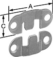 | 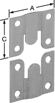 |
Style 2 | Style 3 |
Flat-Surface Brackets
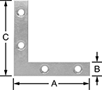 |
Style 1 |
Lg. | Each | ||||||||||||||
|---|---|---|---|---|---|---|---|---|---|---|---|---|---|---|---|
Style | Material | Appearance | (A) | (B) | (C) | Thk. | Wt. Cap. | Mounting Fasteners Included | No. of Mounting Holes | Mounting Hole Style | For Screw Size | 1-49 | 50-Up | ||
| 1 | Zinc-Plated Steel | Dull | 2 1/2" | 1/2" | 2 1/2" | 0.06" | Not Rated | No | 4 | Countersunk | No. 6 | 1558A14 | 00000 | 00000 | |
Lid Supports
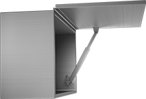 |  |
Side Mount, Opens Up | Side Mount, Opens Up |
Manually control these standard free-moving lid supports through their full range of motion. Raise or lower the lid until the hold-open mechanism on the support is engaged; slightly lift it again to release the hold and close the lid. To secure the lid in a closed position, use a latch or lock (not included). These supports are rated for maximum lid weight—do not exceed the weight listed. They can be used individually but should be used in pairs for lids longer than 24".
Reversible Mount—Reversible-mount supports are for right-side or left-side mounting positions.
Side Mount, Opens Up—Supports for lids that open up from the side are often used in overhead installations.
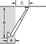
Min. Mounting | For Max. Lid Weight, lb. | Mounting | |||||||||||||||
|---|---|---|---|---|---|---|---|---|---|---|---|---|---|---|---|---|---|
Dp. (A) | Clearance (B) | Lid Mounting Clearance (C) | For Lid Opening Angle | One Lid Support | Two Lid Supports | Material | Appearance | Mounting Location | Performance | Hold Lid Closed | Hardware Included | Screw Size | No. of Holes | Each | |||
Side Mount, Opens Up | |||||||||||||||||
| 1.81" | 9.21" | 4.13" | 75° | 33 | 66 | 304 Stainless Steel | Dull | Left Side, Right Side | Reversible Mount | No | No | No. 6, No. 8 | 5 | 11615A11 | 000000 | ||
| 1.81" | 11.3" | 5.12" | 90° | 33 | 66 | 304 Stainless Steel | Dull | Left Side, Right Side | Reversible Mount | No | No | No. 6, No. 8 | 5 | 11615A12 | 00000 | ||
Folding Table Leg Hinges
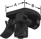 | 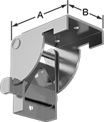 |
For Tubular Legs | For Square Legs |
Cable Tie Mounts
 | 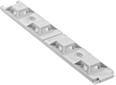 |  |
Style B | Style C | Style L |
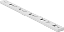 |  |  |
Style G | Style H | Style K |
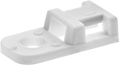
Adhesive Back/Screw In—Nylon
| |
Style B | Style L |
Adhesive-back mounts stick to any clean, smooth surface.
Screw-in mounts require a fastener.
Four Way—Four-way mounts allow ties to be inserted from any side.
UL 94 V-2—Mounts that meet UL 94 V-2 stop burning within 30 seconds.
Adhesive Back/Screw In—ABS
|
Style C |
Adhesive-back mounts stick to any clean, smooth surface.
Screw-in mounts require a fastener.
Four Way—Four-way mounts allow ties to be inserted from any side.
UL 94 V-2—Mounts that meet UL 94 V-2 stop burning within 30 seconds.
For Cable Tie | Overall | Off-White | ||||||||||||
|---|---|---|---|---|---|---|---|---|---|---|---|---|---|---|
Style | For Max. No. of Bundles | Max. Wd. | Max. Thk. | For Screw Size | Lg. | Wd. | For Use Outdoors | Flammability Rating | Temp. Range, ° F | Pkg. Qty. | Pkg. | |||
Four Way | ||||||||||||||
| C | 4 | 0.19" | 0.05" | No. 6 | 5 1/8" | 3/4" | No | UL 94 V-2 | -20 to 120 | 1 | 7582K151 | 00000 | ||
Screw In—Nylon
| | |
Style G | Style H | Style K |
Screw-in mounts require a fastener.
Two Way—Two-way mounts allow ties to be inserted from opposite sides.
Four Way—Four-way mounts allow ties to be inserted from any side.
UL 94 V-2—Mounts that meet UL 94 V-2 stop burning within 30 seconds.
UL 94 V-0—Mounts that meet UL 94 V-0 stop burning within 10 seconds.
For Cable Tie | Overall | Off-White | Black | |||||||||||||||
|---|---|---|---|---|---|---|---|---|---|---|---|---|---|---|---|---|---|---|
Style | For Max. No. of Bundles | Max. Wd. | Max. Thk. | For Screw Size | Lg. | Wd. | For Use Outdoors | Specs. Met | Flammability Rating | Temp. Range, ° F | Pkg. Qty. | Pkg. | Pkg. Qty. | Pkg. | ||||
Two Way | ||||||||||||||||||
| G | 3 | 0.22" | 0.14" | No. 6 | 5 1/16" | 5/8" | No | — | UL 94 V-2 | -60 to 180 | 1 | 7582K153 | 000000 | — | ——— | 0 | ||
| G | 4 | 0.22" | 0.14" | No. 6 | 5 1/2" | 1/2" | No | — | UL 94 V-2 | -60 to 180 | 1 | 7582K154 | 0000 | — | ——— | 0 | ||
| G | 5 | 0.30" | 0.11" | No. 6 | 8 1/8" | 5/8" | No | — | — | -40 to 180 | 1 | 7566K46 | 0000 | — | ——— | 0 | ||
| H | 1 | 0.20" | 0.06" | No. 6 | 5/8" | 3/8" | Yes | UL 62275 Type 21 | UL 94 V-2 | -40 to 180 | — | ——— | 0 | 100 | 7566K104 | 00000 | ||
| H | 1 | 0.21" | 0.05" | No. 6 | 9/16" | 3/8" | No | UL 62275 Type 21 | — | 0 to 180 | 100 | 7566K12 | 00000 | — | ——— | 0 | ||
| H | 1 | 0.22" | 0.06" | No. 6 | 5/8" | 7/16" | No | UL 62275 Type 21 | UL 94 V-0 | -75 to 212 | 10 | 1873N52 | 0000 | — | ——— | 0 | ||
Four Way | ||||||||||||||||||
| K | 1 | 0.20" | 0.09" | No. 6 | 3/4" | 3/8" | No | — | UL 94 V-2 | 32 to 180 | 100 | 7566K102 | 00000 | — | ——— | 0 | ||
Rope Guides
18-8 Stainless Steel
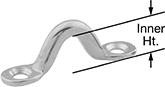 |
18-8 stainless steel guides have good corrosion resistance.
Mounting Holes | ||||||||||||||
|---|---|---|---|---|---|---|---|---|---|---|---|---|---|---|
For Max. Rope Dia. | Wt. Cap. | Lg. | Inner Ht. | Overall Ht. | Thk. | Mounting Fasteners Included | No. of | Dia. | Ctr.-to-Ctr. Lg. | For Mounting Screw Size | Each | |||
1 Line | ||||||||||||||
| 7/16" | Not Rated | 1 7/16" | 1/2" | 9/16" | 3/32" | No | 2 | 5/32" | 1 1/8" | No. 6 | 8860T92 | 00000 | ||
Soft-Closing Lid Supports
 |  |
Side Mount, Opens Up | Top Mount, Opens Up |
|  |
Side Mount, Opens Up | Top Mount, Opens Up |
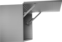
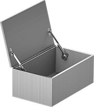
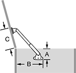
To eliminate slamming and smashed fingers, these supports automatically pull lids shut when they approach the closed position. Raise the lid until the hold-open mechanism on the support is engaged; use a light amount of force to release the hold and close the lid. These supports can be used individually but should be used in pairs for lids longer than 24". Mounting position is determined as you look into your cabinet or chest.
All of these supports are rated for torque instead of maximum lid weight. Calculate your lid's torque and make sure it falls within the range listed—too much torque will cause your lid to slam; too little will prevent it from closing. Torque = Lid Height (inches) × 0.5 × Lid Weight (lbs.).
Reversible Mount—Reversible-mount supports are for right-side or left-side mounting positions.
Side Mount, Opens Up—Supports for lids that open up from the side are often used in overhead installations.
Top Mount, Opens Up—Supports for lids that open up from the top are often used on crates, hatches, and tool chests.
Holds Lid Closed—Supports that hold lid closed are designed to hold lids in the closed position.
Does Not Hold Lid Closed—Supports that do not hold lid closed require a latch or lock (not included) to secure lids in a closed position.
Speed Adjustment Screw—Supports with a speed adjustment screw allow you to control their closing speed.
Min. Mounting | Torque Range, in·lbf | Mounting | ||||||||||||||||
|---|---|---|---|---|---|---|---|---|---|---|---|---|---|---|---|---|---|---|
Dp. (A) | Clearance (B) | Lid Mounting Clearance (C) | For Lid Opening Angle | One Lid Support | Two Lid Supports | Material | Appearance | Mounting Location | Performance | Hold Lid Closed | Hardware Included | Screw Size | No. of Holes | Features | Each | |||
Side Mount, Opens Up | ||||||||||||||||||
| 2.87" | 7.62" | 4.25" | 90° | 19 to 60 | 38 to 120 | Nickel-Plated Steel | Dull | Left Side | — | No | Yes | No. 6 | 6 | Speed Adjustment Screw | 1227A47 | 000000 | ||
| 2.87" | 7.62" | 4.25" | 90° | 19 to 60 | 38 to 120 | Nickel-Plated Steel | Dull | Right Side | — | No | Yes | No. 6 | 6 | Speed Adjustment Screw | 1227A46 | 00000 | ||
| 3.32" | 9.14" | 4.85" | 90° | 35 to 60 | 70 to 120 | Nickel-Plated Steel | Dull | Left Side, Right Side | Reversible Mount | Yes | Yes | No. 6 | 6 | — | 1227A73 | 00000 | ||
| 5.28" | 6.57" | 4.9" | 90° | 61 to 77 | 122 to 154 | Nickel-Plated Steel | Dull | Left Side | — | Yes | Yes | No. 6 | 6 | — | 1227A21 | 00000 | ||
| 5.28" | 6.57" | 4.9" | 90° | 61 to 77 | 122 to 154 | Nickel-Plated Steel | Dull | Right Side | — | Yes | Yes | No. 6 | 6 | — | 1227A22 | 00000 | ||
| 5.28" | 6.57" | 4.9" | 90° | 78 to 95 | 156 to 190 | Nickel-Plated Steel | Dull | Left Side | — | Yes | Yes | No. 6 | 6 | — | 1227A23 | 00000 | ||
| 5.28" | 6.57" | 4.9" | 90° | 78 to 95 | 156 to 190 | Nickel-Plated Steel | Dull | Right Side | — | Yes | Yes | No. 6 | 6 | — | 1227A24 | 00000 | ||
| 5.28" | 6.57" | 4.9" | 90° | 95 to 112 | 190 to 224 | Nickel-Plated Steel | Dull | Left Side | — | Yes | Yes | No. 6 | 6 | — | 1227A25 | 00000 | ||
| 5.28" | 6.57" | 4.9" | 90° | 95 to 112 | 190 to 224 | Nickel-Plated Steel | Dull | Right Side | — | Yes | Yes | No. 6 | 6 | — | 1227A26 | 00000 | ||
| 5.28" | 6.57" | 4.9" | 90° | 130 to 150 | 260 to 300 | Nickel-Plated Steel | Dull | Left Side | — | No | Yes | No. 6 | 6 | — | 1227A27 | 00000 | ||
| 5.28" | 6.57" | 4.9" | 90° | 130 to 150 | 260 to 300 | Nickel-Plated Steel | Dull | Right Side | — | No | Yes | No. 6 | 6 | — | 1227A28 | 00000 | ||
| 7.28" | 10.63" | 6.61" | 90° | 48 to 65 | 96 to 130 | Anodized Aluminum | Dull | Left Side | — | Yes | Yes | No. 6 | 4 | Speed Adjustment Screw | 1227A3 | 00000 | ||
| 7.28" | 10.63" | 6.61" | 90° | 48 to 65 | 96 to 130 | Anodized Aluminum | Dull | Right Side | — | Yes | Yes | No. 6 | 4 | Speed Adjustment Screw | 1227A29 | 00000 | ||
| 7.28" | 10.63" | 6.61" | 90° | 65 to 87 | 130 to 174 | Anodized Aluminum | Dull | Left Side | — | Yes | Yes | No. 6 | 4 | Speed Adjustment Screw | 1227A32 | 00000 | ||
| 7.28" | 10.63" | 6.61" | 90° | 65 to 87 | 130 to 174 | Anodized Aluminum | Dull | Right Side | — | Yes | Yes | No. 6 | 4 | Speed Adjustment Screw | 1227A31 | 00000 | ||
Top Mount, Opens Up | ||||||||||||||||||
| 2.75" | 12.09" | 6.93" | 75° | 30 to 47 | 60 to 94 | Nickel-Plated Steel | Dull | Left Side | — | No | Yes | No. 6 | 6 | — | 1227A17 | 00000 | ||
| 2.75" | 12.09" | 6.93" | 75° | 30 to 47 | 60 to 94 | Nickel-Plated Steel | Dull | Right Side | — | No | Yes | No. 6 | 6 | — | 1227A18 | 00000 | ||
| 2.75" | 12.09" | 6.93" | 75° | 48 to 65 | 96 to 130 | Nickel-Plated Steel | Dull | Left Side | — | No | Yes | No. 6 | 6 | — | 1227A19 | 00000 | ||
| 2.75" | 12.09" | 6.93" | 75° | 48 to 65 | 96 to 130 | Nickel-Plated Steel | Dull | Right Side | — | No | Yes | No. 6 | 6 | — | 1227A2 | 00000 | ||
| 4.84" | 5.84" | 5.84" | 105° | 19 to 60 | 38 to 120 | Nickel-Plated Steel | Dull | Left Side | — | No | Yes | No. 6 | 6 | Speed Adjustment Screw | 1227A45 | 00000 | ||
| 4.84" | 5.84" | 5.84" | 105° | 19 to 60 | 38 to 120 | Nickel-Plated Steel | Dull | Right Side | — | No | Yes | No. 6 | 6 | Speed Adjustment Screw | 1227A44 | 00000 | ||
| 5.12" | 11.25" | 7.99" | 70° | 60 to 86 | 120 to 172 | Nickel-Plated Steel | Dull | Left Side | — | No | Yes | No. 6 | 6 | — | 1227A11 | 00000 | ||
| 5.12" | 11.25" | 7.99" | 70° | 60 to 86 | 120 to 172 | Nickel-Plated Steel | Dull | Right Side | — | No | Yes | No. 6 | 6 | — | 1227A12 | 00000 | ||
| 5.12" | 11.25" | 7.99" | 70° | 86 to 108 | 172 to 216 | Nickel-Plated Steel | Dull | Left Side | — | No | Yes | No. 6 | 6 | — | 1227A13 | 00000 | ||
| 5.12" | 11.25" | 7.99" | 70° | 86 to 108 | 172 to 216 | Nickel-Plated Steel | Dull | Right Side | — | No | Yes | No. 6 | 6 | — | 1227A14 | 00000 | ||
| 5.12" | 11.25" | 7.99" | 70° | 108 to 130 | 216 to 260 | Nickel-Plated Steel | Dull | Left Side | — | No | Yes | No. 6 | 6 | — | 1227A16 | 00000 | ||
| 5.12" | 11.25" | 7.99" | 70° | 108 to 130 | 216 to 260 | Nickel-Plated Steel | Dull | Right Side | — | No | Yes | No. 6 | 6 | — | 1227A15 | 00000 | ||
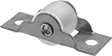
Cabinet Door and Drawer Rollers
 |
Roller | |||||||||
|---|---|---|---|---|---|---|---|---|---|
Dia. | Material | Lg. | Wd. | Material | Mounting Fasteners Included | Mounting Screw Size | Each | ||
| 3/4" | Steel | 2" | 1" | Steel | No | No. 6 | 1714A3 | 00000 | |
Soft-Closing Heavy Duty Base- and Under-Mount Drawer Slides
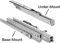 | 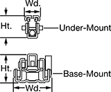 |
To prevent drawers from slamming shut and support them even if they’re tall and full of heavy equipment, these steel slides have soft-closing bumpers and mount to the top and bottom of drawers. They’re commonly used in washdown areas such as kitchens because they have a powder coating to prevent rust and their ball bearings are encased to keep liquid out. Since they’re encased, the ball bearings spread weight more evenly than standard ball bearings, which makes them quieter and support more weight. To make sure the bearings don’t wobble or fall off track because of heavy loads, these slides have rail guides. Slides maintain a consistent amount of support as you fully extend them, so reaching deep inside drawers isn’t an issue. All are LGA tested according to DIN 4554 for safety, performance, and quality.
Bottom Slide | Top Slide | Mounting | |||||||||||||||
|---|---|---|---|---|---|---|---|---|---|---|---|---|---|---|---|---|---|
Closed Lg. | Travel Lg. | Mounting Location | Wd. | Ht. | Mounting Location | Wd. | Ht. | Wt. Cap. per Pair, lb. | Roller Type | Fasteners Included | Screw Size | Color | Extension | Pair | |||
Powder-Coated Steel | |||||||||||||||||
Without Release | |||||||||||||||||
| 22 5/8" | 22" | Base | 4 5/16" | 3 1/8" | Under Mount | 1 9/16" | 2 5/16" | 275 | Ball Bearing | No | 1/4", No. 10, No. 6 | White | Full | 7550N111 | 0000000 | ||
Cable Holders
 |  |
Style N | Style Q |
Mount to a surface to secure and route cable.
Adhesive Back/Screw In
|
Style N |
Adhesive-back cable holders mount to any clean, dry surface.
Screw-in mount cable holders require a fastener.
Overall | Pkg. | |||||||||||||||
|---|---|---|---|---|---|---|---|---|---|---|---|---|---|---|---|---|
Style | For Max. Bundle Dia. | For Screw Size | Mounting Hole Dia. | Lg. | Wd. | Ht. | For Use Outdoors | Temp. Range, ° F | Color | Pkg. Qty. | 1-4 | 5-19 | 20-Up | |||
Nylon | ||||||||||||||||
| N | 1/8" | No. 6 | 0.14" | 2 9/16" | 1/2" | 1/8" | No | -20 to 120 | Gray | 5 | 2024N551 | 00000 | 00000 | 00000 | ||
| N | 1/8" | No. 6 | 0.14" | 3 5/16" | 1/2" | 1/8" | No | -20 to 120 | Gray | 5 | 2024N552 | 0000 | 0000 | 0000 | ||
| N | 1/8" | No. 6 | 0.14" | 4 9/16" | 1/2" | 1/8" | No | -20 to 120 | Gray | 5 | 2024N553 | 00000 | 00000 | 0000 | ||
Screw In
|
Style Q |
Screw-in mount cable holders require a fastener.
Overall | Pkg. | ||||||||||||||||
|---|---|---|---|---|---|---|---|---|---|---|---|---|---|---|---|---|---|
Style | For Max. Bundle Dia. | For Screw Size | Mounting Hole Dia. | Lg. | Wd. | Ht. | For Use Outdoors | Flammability Rating | Temp. Range, ° F | Color | Pkg. Qty. | 1-9 | 10-99 | 100-Up | |||
Nylon | |||||||||||||||||
| Q | 3/8" | No. 6 | 0.15" | 1 7/16" | 3/8" | 3/8" | Yes | UL 94 V-2 | -75 to 185 | Black | 10 | 2024N601 | 00000 | 00000 | 00000 | ||
Wraparound Rope Cleats
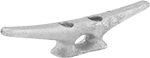 | 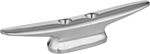 | 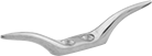 |
Style A | Style C | Style E |
Style A
|
Bolt On—Bolt-on cleats have exposed fasteners that attach directly to the deck or other surface.
Style C
|
Bolt On—Bolt-on cleats have exposed fasteners that attach directly to the deck or other surface.
Brass—Brass cleats are often used in marine environments.
Mounting Holes | |||||||||||
|---|---|---|---|---|---|---|---|---|---|---|---|
For Max. Rope Dia. | Lg. | Overall Ht. | Mounting Fasteners Included | No. of | Dia. | Ctr.-to-Ctr. Lg. | For Mounting Screw Size | Each | |||
Bolt On | |||||||||||
Brass | |||||||||||
| 3/16" | 3 3/16" | 13/16" | No | 2 | 3/16" | 11/16" | No. 6 | 33805T849 | 000000 | ||
Style E
|
Bolt On—Bolt-on cleats have exposed fasteners that attach directly to the deck or other surface.
Brass—Brass cleats are often used in marine environments.
Mounting Holes | |||||||||||
|---|---|---|---|---|---|---|---|---|---|---|---|
For Max. Rope Dia. | Lg. | Overall Ht. | Mounting Fasteners Included | No. of | Dia. | Ctr.-to-Ctr. Lg. | For Mounting Screw Size | Each | |||
Bolt On | |||||||||||
Brass | |||||||||||
| 3/16" | 2 1/2" | 1/2" | No | 2 | 5/32" | 1/2" | No. 6 | 33805T51 | 00000 | ||
Self-Opening Lid Supports
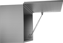 |  |
Side Mount, Opens Up | Top Mount, Opens Up |
| |
Top Mount, Opens Up | Side Mount, Opens Up |
Min. Mounting | For Max. Lid Weight, lb. | Mounting | ||||||||||||||||
|---|---|---|---|---|---|---|---|---|---|---|---|---|---|---|---|---|---|---|
Dp. (A) | Clearance (B) | Lid Mounting Clearance (C) | For Lid Opening Angle | One Lid Support | Two Lid Supports | Material | Appearance | Spring Material | Mounting Location | Performance | Hold Lid Closed | Hardware Included | Screw Size | No. of Holes | Each | |||
Side Mount, Opens Up; Top Mount, Opens Up | ||||||||||||||||||
| 1.81" | 9.25" | 3.44" | 90° | 2.75 | 5.5 | 304 Stainless Steel | Dull | Nickel Steel | Left Side, Right Side | Reversible Mount | Yes | No | No. 6 | 5 | 11615A13 | 000000 | ||
| 1.81" | 13.54" | 4.82" | 90° | 3.4 | 6.8 | 304 Stainless Steel | Dull | Nickel Steel | Left Side, Right Side | Reversible Mount | Yes | No | No. 6 | 5 | 11615A14 | 00000 | ||
Top Mount, Opens Up | ||||||||||||||||||
| 2.44" | 1.58" | 13.09" | 110° | 2.75 | 5.5 | 304 Stainless Steel | Dull | Nickel Steel | Left Side, Right Side | Reversible Mount | Yes | No | No. 6 | 5 | 11615A15 | 00000 | ||
Soft-Opening Lid Supports
 |  |
Side Mount, Opens Down |
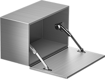
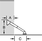
Gradually slow your lid's motion to prevent it from slamming open. To open lids, lower them and the support will slowly and softly do the rest. Manually shut the lids and the supports will hold them in the closed position. Designed for use on lids that open down from the side, these supports allow lids to double as a work surface when they are open, similar to a drop-leaf desk. They can be used individually but should be used in pairs for lids longer than 24". Mounting position is determined as you look into your cabinet or chest.
All of these supports are rated for torque instead of maximum lid weight. Calculate your lid's torque and make sure it falls within the range listed—too much torque will cause your lid to slam; too little will prevent it from closing. Torque = Lid Height (inches) × 0.5 × Lid Weight (lbs.). An adjustment screw allows you to control the opening speed.
Reversible Mount—Reversible-mount supports are for right-side or left-side mounting positions.
Min. Mounting | Torque Range, in·lbf | Mounting | |||||||||||||||
|---|---|---|---|---|---|---|---|---|---|---|---|---|---|---|---|---|---|
Dp. (A) | Clearance (B) | Lid Mounting Clearance (C) | For Lid Opening Angle | One Lid Support | Two Lid Supports | Material | Appearance | Mounting Location | Performance | Hold Lid Closed | Hardware Included | Screw Size | No. of Holes | Each | |||
Side Mount, Opens Down | |||||||||||||||||
| 2.84" | 8.31" | 4.46" | 90° | 19 to 60 | 38 to 120 | Nickel-Plated Steel | Dull | Left Side | — | Yes | Yes | No. 6 | 6 | 1227A43 | 000000 | ||
| 2.84" | 8.31" | 4.46" | 90° | 19 to 60 | 38 to 120 | Nickel-Plated Steel | Dull | Right Side | — | Yes | Yes | No. 6 | 6 | 1227A42 | 00000 | ||
| 3.32" | 8.86" | 4.85" | 90° | 30 to 43 | 60 to 86 | Nickel-Plated Steel | Dull | Left Side, Right Side | Reversible Mount | Yes | Yes | No. 6 | 6 | 1227A71 | 00000 | ||
Mountable Cable Ties
Screw In
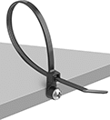 |
Our most secure mount won’t pull out or shake loose. Drill into surfaces and fasten through the head.
Nylon—Wear resistant for long life, these ties are the go-to for most applications. However, they can swell and weaken from moisture, so they’re best for dry environments.
Off-White | Black | ||||||||||||||
|---|---|---|---|---|---|---|---|---|---|---|---|---|---|---|---|
Lg. | For Max. Bundle Dia. | Breaking Strength | Wd. | Thk. | For Screw Size | UV Protection | Pkg. Qty. | Pkg. | UV Protection | Pkg. Qty. | Pkg. | ||||
Nylon | |||||||||||||||
Narrow | |||||||||||||||
| 4" | 0.87" | 18 lbf | 0.10" | 0.04" | No. 6 | None | 100 | 2056N19 | 00000 | — | — | ——— | 0 | ||
Wide | |||||||||||||||
| 8" | 2" | 50 lbf | 0.38" | 0.05" | No. 6 | — | — | ——— | 0 | UV Resistant | 15 | 1508N11 | 00000 | ||
| 11" | 3" | 50 lbf | 0.38" | 0.05" | No. 6 | — | — | ——— | 0 | UV Resistant | 15 | 1508N12 | 0000 | ||
| 14" | 4" | 50 lbf | 0.38" | 0.05" | No. 6 | — | — | ——— | 0 | UV Resistant | 15 | 1508N13 | 0000 | ||
Extra Wide | |||||||||||||||
| 4 1/2" | 1" | Not Rated | 0.50" | 0.04" | No. 6 | — | — | ——— | 0 | None | 10 | 7565K51 | 00000 | ||
| 6" | 1 1/2" | Not Rated | 0.50" | 0.04" | No. 6 | — | — | ——— | 0 | None | 10 | 7565K52 | 00000 | ||
| 7 1/2" | 2" | Not Rated | 1" | 0.04" | No. 6 | — | — | ——— | 0 | None | 10 | 7565K53 | 00000 | ||
Mirror Holders

Spring Lid Supports
 |  |
Top Mount, Opens Up |
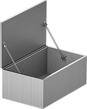
Also known as hatch springs, these supports are commonly used on hatches and other top-opening lids. Raise the lid to extend the spring, which props the lid open—an internal cable keeps the spring from overextending. Press the center of the spring to release the hold and close the lid. To secure the lid in a closed position, use a latch or lock (not included). These supports are rated for maximum lid weight—do not exceed the weight listed. They can be used individually but should be used in pairs for lids longer than 24".
Reversible Mount—Reversible-mount supports are for right-side or left-side mounting positions.
Top Mount, Opens Up—Supports for lids that open up from the top are often used on crates, hatches, and tool chests.
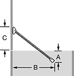
Min. Mounting | For Max. Lid Weight, lb. | Mounting | ||||||||||||||||
|---|---|---|---|---|---|---|---|---|---|---|---|---|---|---|---|---|---|---|
Dp. (A) | Clearance (B) | Lid Mounting Clearance (C) | For Lid Opening Angle | One Lid Support | Two Lid Supports | Lg. | Dia. | Material | Mounting Location | Performance | Hold Lid Closed | Hardware Included | Screw Size | No. of Holes | Each | |||
Top Mount, Opens Up | ||||||||||||||||||
| 2.5" | 6.36" | 3.86" | 90° | 20 | 40 | 9" | 7/16" | 304 Stainless Steel | Left Side, Right Side | Reversible Mount | No | No | No. 6 | 4 | 7008N12 | 000000 | ||
Standoff Cable Tie Mounts
 |
Style A |
Often used to secure vertical running material, these mounts maintain space between a bundle and a surface.
For Cable Tie | Overall | Black | |||||||||||||
|---|---|---|---|---|---|---|---|---|---|---|---|---|---|---|---|
Style | For Max. No. of Bundles | Max. Wd. | Max. Thk. | For Screw Size | Mounting Hole Dia. | Lg. | Wd. | Ht. | For Use Outdoors | Specs. Met | Temp. Range, ° F | Each | |||
Screw In—Nylon | |||||||||||||||
Two Way | |||||||||||||||
| A | 1 | 0.14" | 0.05" | No. 6 | 0.15" | 3/4" | 5/8" | 1 3/4" | No | UL 62275 Type 21 | -75 to 185 | 1951N45 | 00000 | ||
| A | 1 | 0.14" | 0.05" | No. 6 | 0.15" | 3/4" | 5/8" | 2 3/4" | No | UL 62275 Type 21 | -75 to 185 | 1951N46 | 0000 | ||
| A | 1 | 0.14" | 0.05" | No. 6 | 0.15" | 3/4" | 5/8" | 3 13/16" | No | UL 62275 Type 21 | -75 to 185 | 1951N47 | 0000 | ||
T-Tracks
Single-Profile Perpendicular T-Tracks
 |  |  |
Inside | Mounting Holes | For Mounting Screw | |||||||||||||
|---|---|---|---|---|---|---|---|---|---|---|---|---|---|---|---|
Lg. | Wd. | Ht. | Width | Height | Mounting Fasteners Included | Number of | Center-to-Center | Size | Head Style | Material | No. of Pieces | Each | |||
3/8" Wide Slot | |||||||||||||||
| 4" | 3/4" | 1/2" | 1/2" | 1/4" | No | 2 | 2" | No. 6 | Pan | Anodized Aluminum | 4 | 1850A12 | 000000 | ||
Metal-Detectable Cable Tie Mounts
 |
Adhesive Back |
Use these plastic mounts with metal-detector-grade cable ties when detection and retrieval is essential, such as in food processing applications. Mounts are brightly colored for visibility and contain a special compound that can be picked up by X-ray equipment and metal detectors.
Adhesive Back—Adhesive-back mounts stick to any clean, smooth surface. All components are FDA compliant.
Four Way—Four-way mounts allow ties to be inserted from any side.
For Cable Tie | Overall | Green | |||||||||||||
|---|---|---|---|---|---|---|---|---|---|---|---|---|---|---|---|
For Max. No. of Bundles | Max. Wd. | Max. Thk. | For Screw Size | Mounting Hole Dia. | Lg. | Wd. | Ht. | For Use Outdoors | Food Industry Std. | Temp. Range, ° F | Pkg. Qty. | Pkg. | |||
Adhesive Back—Nylon | |||||||||||||||
Four Way | |||||||||||||||
| 1 | 0.20" | 0.06" | No. 6 | 0.21" | 1" | 1" | 3/16" | No | FDA Compliant 21 CFR 175.125, FDA Compliant 21 CFR 177.1500, FDA Compliant 21 CFR 184.1375 | 32 to 155 | 25 | 1922N12 | 000000 | ||
Heavy Duty Base- and Under-Mount Drawer Slides
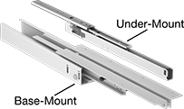 | 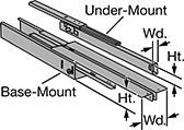 |
Base- and Under-Mount Drawer Slides | |
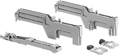 | |
Slow-Close Attachment |
Mounting to the tops and bottoms of drawers, these steel slides support drawers even if they’re tall and hold heavy equipment. They’re often used in kitchens and other washdown areas because they’re powder-coated to resist rusting and their ball bearings are encased to keep out liquid. The encased ball bearings also distribute weight more evenly than standard ball bearings, which means they’re quieter and support more weight. To keep the bearings from wobbling or falling off track due to heavy loads, these slides have rail guides. Slides maintain a constant amount of support as you fully extend them, so accessing deep inside drawers isn’t a problem. All are LGA tested according to DIN 4554 for safety, performance, and quality.
Slow-Closing Attachments—Add slow-closing attachments to keep drawers from slamming.
Slides | Slow-Closing Attachments | ||||||||||||||||||
|---|---|---|---|---|---|---|---|---|---|---|---|---|---|---|---|---|---|---|---|
Bottom Slide | Top Slide | Mounting | |||||||||||||||||
Closed Lg. | Travel Lg. | Mounting Location | Wd. | Ht. | Mounting Location | Wd. | Ht. | Wt. Cap. per Pair, lb. | Roller Type | Fasteners Included | Screw Size | Color | Extension | Pair | Pair | ||||
Without Release | |||||||||||||||||||
| 17 3/4" | 17 1/16" | Base | 5 1/16" | 3 9/16" | Under Mount | 1 9/16" | 2 5/16" | 440 | Ball Bearing | No | 1/4", No. 6 | White | Full | 7820N11 | 0000000 | 7820N15 | 000000 | ||
| 19 11/16" | 19 1/16" | Base | 5 1/16" | 3 9/16" | Under Mount | 1 9/16" | 2 5/16" | 440 | Ball Bearing | No | 1/4", No. 6 | White | Full | 7820N12 | 000000 | 7820N15 | 00000 | ||
| 21 5/8" | 21" | Base | 5 1/16" | 3 9/16" | Under Mount | 1 9/16" | 2 5/16" | 440 | Ball Bearing | No | 1/4", No. 6 | White | Full | 7820N13 | 000000 | 7820N15 | 00000 | ||
| 23 5/8" | 23" | Base | 5 1/16" | 3 9/16" | Under Mount | 1 9/16" | 2 5/16" | 440 | Ball Bearing | No | 1/4", No. 6 | White | Full | 7820N14 | 000000 | 7820N15 | 00000 | ||
