


Filter by
Product Family
Input Voltage
Output Voltage
Sensor Type
Electrical Connection
Measures
Export Control Classification Number (ECCN)
Connects To
DFARS Specialty Metals
Barcode Symbology
Logic Level Converters for Development Boards
Input/Output | |||||||||
|---|---|---|---|---|---|---|---|---|---|
Voltage, V DC | Signal Type | No. of Channels | Lg. | Wd. | Hole Ctr.-to-Ctr. | Each | |||
Bidirectional Channel | |||||||||
| 0.8 to 5 | Digital | 4 | 5/8" | 9/16" | 0.1" | 4894N11 | 00000 | ||
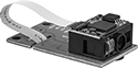
Distance-Measuring Modules for Development Boards
Ultrasonic Modules
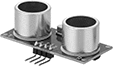 |
Ultrasonic modules use sound pulses to measure distance. They can be used in low lighting. However, they may not be accurate on soft, small, or oddly shaped objects that won’t reflect sound waves properly.
Sensing Distance | Accuracy | Output Data Freq., Hz | Measures | Temp. Range, ° F | Input Voltage, V DC | Connection Method | Lg. | Wd. | Ht. | Each | |||
|---|---|---|---|---|---|---|---|---|---|---|---|---|---|
| 2 cm to 4 m | ±0.3 cm | 40 | Distance | 32 to 100 | 5 | Push In, Solder | 1 3/4" | 3/4" | 1/2" | 7132N13 | 00000 | ||
Infrared LED Modules
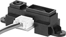 |  |
Wire Leads Connection | Qwiic Connection |
Infrared LED modules bounce light off an object and back into their own sensor to measure distance.
I²C Communication Protocol—Modules with I²C protocol make setup and data collection simple. They convert readings into an electrical signal to transmit to your board.
Qwiic Connection—Those with a Qwiic connection are easily installed using Qwiic cords.
Output Data | |||||||||||||||||||
|---|---|---|---|---|---|---|---|---|---|---|---|---|---|---|---|---|---|---|---|
Sensing Distance | Sensing Distance Resolution, cm | Accuracy | Resolution, bit | Freq., Hz | Measures | Temp. Range, ° F | Input Voltage, V DC | I2C Address | Connection Method | No. of Qwiic Connections | No. of Wire Leads | Wire Lead Lg. | Lg. | Wd. | Ht. | Each | |||
Wire Leads Connection | |||||||||||||||||||
| 4 cm to 30 cm | — | — | — | 50 | Distance | 15 to 140 | 4.5 to 5.5 | — | Solder | — | 3 | 5" | 1 3/4" | 3/4" | 9/16" | 7132N18 | 000000 | ||
| 10 cm to 80 cm | — | — | — | 20 | Distance | 15 to 140 | 4.5 to 5.5 | — | Solder | — | 3 | 5" | 1 3/4" | 3/4" | 9/16" | 7132N17 | 00000 | ||
I²C Communication Protocol—Qwiic Connection | |||||||||||||||||||
| 5 cm to 10 m | 1 | ±1 cm | 7 | 200 | Distance | 0 to 140 | 3.3 | 0x62 | Solder | 2 | — | — | 2 5/16" | 1" | 7/8" | 7132N12 | 000000 | ||
Laser Modules
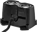 |
Laser modules quickly and accurately detect objects up to 40 meters away. Choose them to measure the distance of fast-moving objects.
I²C Communication Protocol—Modules with I²C protocol make setup and data collection simple. They convert readings into an electrical signal to transmit to your board.
Output Data | ||||||||||||||||||
|---|---|---|---|---|---|---|---|---|---|---|---|---|---|---|---|---|---|---|
Sensing Distance, m | Sensing Distance Resolution, cm | Accuracy | Resolution, bit | Freq., kHz | Measures | Temp. Range, ° F | Input Voltage, V DC | I2C Address | No. of Wire Leads | Wire Lead Lg. | Lg. | Wd. | Ht. | Enclosure Rating | Each | |||
I²C Communication Protocol—Wire Leads Connection | ||||||||||||||||||
| 1 to 40 | 1 | ±2.5 cm | 7 | 1 | Distance | 0 to 140 | 4.75 to 5 | 0x62 | 6 | 7 3/4" | 2 1/8" | 1" | 1 5/16" | IP07 | 7132N11 | 0000000 | ||
Barcode Scanner Modules for Development Boards
Modules with Barcode Scanner
 |
Scan | For Symbology Type | ||||||||||||||
|---|---|---|---|---|---|---|---|---|---|---|---|---|---|---|---|
Distance | Speed, in/sec | Scanner Resolution | 1D Scanner | 2D Scanner | Output Data Resolution, bit | Temp. Range, ° F | Input Voltage, V DC | No. of USB Connections | Connection Method | Lg. | Wd. | Each | |||
USB-C Connection | |||||||||||||||
| 1" to 15 3/4" | 9.8 | 640 × 480 | Codabar Code 11 Code 39 Code 93 Code 128 Datalogic 2 of 5 EAN-8 EAN-13 GS1 Databar GS1-128 Industrial 2 of 5 Interleaved 2 of 5 Matrix 2 of 5 MSI UPC-A UPC-E | Aztec Code Data Matrix Micro PDF 417 PDF 417 QR Code | 32 | 0 to 120 | 3.3 | 1 | Solder | 1 3/4" | 1" | 5716N11 | 000000 | ||
Motion-Measuring Modules for Development Boards
Modules with Accelerometer
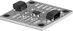 |
An accelerometer measures the rate at which your device is speeding up or slowing down.
Output Data | ||||||||||||||
|---|---|---|---|---|---|---|---|---|---|---|---|---|---|---|
Accel., g | Resolution, bit | Freq., kHz | Measures | Temp. Range, ° F | Input Voltage, V DC | I2C Address | Connection Method | No. of Qwiic Connections | Lg. | Wd. | Each | |||
I²C Communication Protocol—Qwiic Connection | ||||||||||||||
| 8 16 32 64 | 16 | 10 | Acceleration | -40 to 220 | 1.2 to 3.6 | 0x1E 0x1F | Solder | 2 | 1" | 1" | 8184N11 | 000000 | ||
Modules with Magnetometer
|
A magnetometer measures your device's orientation.
Output Data | ||||||||||||||
|---|---|---|---|---|---|---|---|---|---|---|---|---|---|---|
Magnetic Field Measuring, G | Resolution, bit | Freq., kHz | Measures | Temp. Range, ° F | Input Voltage, V DC | I2C Address | Connection Method | No. of Qwiic Connections | Lg. | Wd. | Each | |||
I²C Communication Protocol—Qwiic Connection | ||||||||||||||
| 0 to 8 | 18 | 1 | Magnetic Field Strength | -40 to 220 | 2.8 to 3.6 | 0x30 | Solder | 1 | 3/4" | 5/16" | 8184N14 | 000000 | ||
Modules with Accelerometer and Gyroscope
|
A gyroscope measures how fast your device is rotating.
An accelerometer measures the rate at which your device is speeding up or slowing down.
Output Data | |||||||||||||||
|---|---|---|---|---|---|---|---|---|---|---|---|---|---|---|---|
Accel., g | Velocity | Resolution, bit | Freq., kHz | Measures | Temp. Range, ° F | Input Voltage, V DC | I2C Address | Connection Method | No. of Qwiic Connections | Lg. | Wd. | Each | |||
I²C Communication Protocol—Qwiic Connection | |||||||||||||||
| 2 4 8 16 | 125 °/s 250 °/s 500 °/s 1,000 °/s 2,000 °/s 4,000 °/s | 16 | 7.68 | Acceleration, Angular Velocity | -40 to 185 | 1.71 to 3.6 | 0x6A 0x6B | Solder | 2 | 1" | 1" | 8184N12 | 000000 | ||
Modules with Accelerometer, Gyroscope, Magnetometer
|
A gyroscope measures how fast your device is rotating.
A magnetometer measures your device's orientation.
An accelerometer measures the rate at which your device is speeding up or slowing down.
Output Data | ||||||||||||||||
|---|---|---|---|---|---|---|---|---|---|---|---|---|---|---|---|---|
Accel., g | Velocity | Magnetic Field Measuring, G | Resolution, bit | Freq., kHz | Measures | Temp. Range, ° F | Input Voltage, V DC | I2C Address | Connection Method | No. of Qwiic Connections | Lg. | Wd. | Each | |||
I²C Communication Protocol—Qwiic Connection | ||||||||||||||||
| 2 4 8 16 | 125 °/s 250 °/s 500 °/s 1,000 °/s 2,000 °/s 4,000 °/s | 0 to 8 | 18 | 1 | Acceleration, Angular Velocity, Magnetic Field Strength | -40 to 220 | 1.71 to 3.6 | 0x6A 0x6B 0x30 | Solder | 2 | 1" | 1" | 8184N13 | 000000 | ||
Absolute Pressure Transmitters for Development Boards
 |
Measure your equipment’s pressure and send the data directly to a development board or single-board computer. Also known as transducers, these transmitters convert pressure into an electrical I2C signal and transmit it to your board by connecting a cord (not included) with a Qwiic connection. Transmitters connect directly to your machinery via tubing (not included), letting you monitor activity such as gas tank pressurization and liquid fill level.
Unlike other pressure transmitters that measure the difference between your system and the atmosphere, these transmitters give measurements relative to zero pressure—regardless of altitude or temperature. They will only provide accurate readings within the rated pressure range.
Pressure Range, psi | Max. Continuous Pressure, psi | Max. Short-Term Pressure, psi | Input Voltage, V DC | For Tube ID | I2C Address | Number of Qwiic Connections | Ht. | Wd. | For Use With | Accuracy | Housing Material | Connection Material | Temp. Range, ° F | Each | |||
|---|---|---|---|---|---|---|---|---|---|---|---|---|---|---|---|---|---|
I²C Communication Protocol—Qwiic Connection | |||||||||||||||||
Unthreaded Male Tube Connection | |||||||||||||||||
| 1 to 25 | 60 | 60 | 1.8 to 3.6 | 0.1" | 0x18 | 2 | 1" | 1" | Air Argon Nitrogen Water | ±0.25% | Stainless Steel | Stainless Steel | 30 to 120 | 7412N11 | 000000 | ||
Development Board Programming Modules
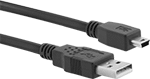 | |
6 ft. USB Cords |
Program mini development boards and other custom circuit boards with these modules. To program your board, attach the module and connect it to your computer using a USB cord (sold separately). Then transfer the code from your computer to the development board. Once the board has been programmed, the module can be removed. Choose an operating voltage that supports the board you’re programming.
Programming Modules | 6 ft. USB Cords | |||||||||||
|---|---|---|---|---|---|---|---|---|---|---|---|---|
Operating Voltage, V DC | Electrical Connection | Header Gender | Hole Ctr.-to-Ctr. | Lg. | Wd. | For Mfr. | For Mfr. Series | Each | Each | |||
| 5 | Mini USB-B | Female | 0.1" | 1 1/8" | 7/8" | Arduino | LilyPad, Pro, Pro Mini | 4003N11 | 000000 | 4974T32 | 00000 | |
| 3.3 | Mini USB-B | Female | 0.1" | 1 3/16" | 3/8" | Arduino | LilyPad, Pro, Pro Mini | 4003N12 | 00000 | 4974T32 | 0000 | |
Circuit Board Voltage Regulators
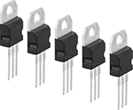 |
Safely power low-voltage components in circuits with a high-voltage source. These regulators turn high-voltage inputs into lower, more stable outputs.
Adjustable Output Voltage—Regulators with an adjustable output voltage let you fine-tune the output to best fit your circuit. To adjust the output voltage, connect them to two resistors (not included). The resistance values determine your output voltage.
Dropout Voltage—Dropout voltage is the minimum required difference between the input voltage and your regulator’s output voltage.
Input Voltage, V DC | Terminal | |||||||||||||||||
|---|---|---|---|---|---|---|---|---|---|---|---|---|---|---|---|---|---|---|
Output Voltage, V DC | Min. | Max. | Dropout Voltage, V DC | Max. Current, amp | Electronic Component Trade Size | Electronic Component Trade No. | No. of | Lg. | Material | For Hole Ctr.-to-Ctr. | Ht. | Wd. | Dp. | Pkg. Qty. | Pkg. | |||
Fixed Output Voltage | ||||||||||||||||||
Positive | ||||||||||||||||||
| 5 | 8 | 35 | 2 | 1.5 | TO-220 | L7805 | 3 | 9/16" | Tin-Plated Copper | 0.1" | 5/8" | 13/32" | 3/16" | 5 | 7627N11 | 00000 | ||
| 6 | 11 | 35 | 2 | 1.5 | TO-220 | L7806 | 3 | 9/16" | Tin-Plated Copper | 0.1" | 5/8" | 13/32" | 3/16" | 5 | 7627N12 | 0000 | ||
| 8 | 14 | 35 | 2 | 1.5 | TO-220 | L7808 | 3 | 9/16" | Tin-Plated Copper | 0.1" | 5/8" | 13/32" | 3/16" | 5 | 7627N13 | 0000 | ||
| 9 | 15 | 35 | 2 | 1.5 | TO-220 | L7809 | 3 | 9/16" | Tin-Plated Copper | 0.1" | 5/8" | 13/32" | 3/16" | 5 | 7627N14 | 0000 | ||
| 12 | 16 | 35 | 2 | 1.5 | TO-220 | L7812 | 3 | 9/16" | Tin-Plated Copper | 0.1" | 5/8" | 13/32" | 3/16" | 5 | 7627N15 | 0000 | ||
| 15 | 19 | 35 | 2 | 1.5 | TO-220 | L7815 | 3 | 9/16" | Tin-Plated Copper | 0.1" | 5/8" | 13/32" | 3/16" | 5 | 7627N16 | 0000 | ||
| 24 | 28 | 35 | 2 | 1.5 | TO-220 | L7824 | 3 | 9/16" | Tin-Plated Copper | 0.1" | 5/8" | 13/32" | 3/16" | 5 | 7627N17 | 0000 | ||
Negative | ||||||||||||||||||
| -15 | -35 | -19 | 2 | 1.5 | TO-220 | L7915 | 3 | 9/16" | Tin-Plated Copper | 0.1" | 5/8" | 13/32" | 3/16" | 5 | 7627N24 | 0000 | ||
| -12 | -35 | -16 | 1.1 | 1.5 | TO-220 | L7912 | 3 | 9/16" | Tin-Plated Copper | 0.1" | 5/8" | 13/32" | 3/16" | 5 | 7627N23 | 0000 | ||
| -9 | -35 | -15 | 2 | 1.5 | TO-220 | L7909 | 3 | 9/16" | Tin-Plated Copper | 0.1" | 5/8" | 13/32" | 3/16" | 5 | 7627N22 | 0000 | ||
| -8 | -35 | -14 | 2 | 1.5 | TO-220 | L7908 | 3 | 9/16" | Tin-Plated Copper | 0.1" | 5/8" | 13/32" | 3/16" | 5 | 7627N21 | 0000 | ||
| -6 | -35 | -11 | 2 | 1.5 | TO-220 | L7906 | 3 | 9/16" | Tin-Plated Copper | 0.1" | 5/8" | 13/32" | 3/16" | 5 | 7627N19 | 0000 | ||
| -5 | -35 | -8 | 1.1 | 1.5 | TO-220 | L7905 | 3 | 9/16" | Tin-Plated Copper | 0.1" | 5/8" | 13/32" | 3/16" | 5 | 7627N18 | 0000 | ||
Adjustable Output Voltage | ||||||||||||||||||
Positive | ||||||||||||||||||
| 1.25 to 37 | 4.25 | 40 | 1.25 | 1.5 | TO-220 | LM317 | 3 | 9/16" | Tin-Plated Copper | 0.1" | 5/8" | 13/32" | 3/16" | 5 | 7627N25 | 0000 | ||
Environmental-Monitoring Modules for Development Boards
Modules with Air Quality Sensor
Modules with an air quality sensor identify spikes in VOC levels to track air quality changes. Instead of directly measuring VOCs, they measure how much the VOC level has changed in the last 24 hours.
Output Data | |||||||||||||
|---|---|---|---|---|---|---|---|---|---|---|---|---|---|
Resolution, bit | Freq., Hz | Measures | Relative Volatile Organic Compound Index | Input Voltage, V DC | I2C Address | Connection Method | No. of Qwiic Connections | Lg. | Wd. | Each | |||
I²C Communication Protocol—Qwiic Connection | |||||||||||||
| 16 | 33 | Relative Volatile Organic Compound Concentration | 0 to 500 | 1.7 to 3.6 | 0x59 | Solder | 2 | 1" | 1" | 7126N13 | 000000 | ||
Modules with Temperature, Humidity, and Air Quality Sensor
Modules with a temperature, humidity, and air quality sensor help you make sure the air is healthy in your facility. They directly measure the amount of carbon dioxide in the air.
Output Data | |||||||||||||||
|---|---|---|---|---|---|---|---|---|---|---|---|---|---|---|---|
Resolution, bit | Freq., Hz | Measures | Temp. Range, ° C | RH | Carbon Dioxide Concentration Measured, ppm | Input Voltage, V DC | I2C Address | Connection Method | No. of Qwiic Connections | Lg. | Wd. | Each | |||
I²C Communication Protocol—Qwiic Connection | |||||||||||||||
| 16 | 0.2 | Temperature, Relative Humidity, Carbon Dioxide Level | -10 to 60 | 0% to 100% | 0 to 40,000 | 2.4 to 5.5 | 0x62 | Solder | 2 | 1" | 1" | 7126N11 | 000000 | ||
Modules with Temperature, Humidity, and Barometer Sensor
Modules with a temperature, humidity, and barometer sensor are often used as part of an automated system that runs equipment based on the weather. For instance, you can use them in a system that will turn on a humidifier if humidity dips below a certain level.
Measures | Temp. Range, ° C | RH | Barometric Pressure, in. Hg | Input Voltage, V DC | I2C Address | Connection Method | No. of Qwiic Connections | Lg. | Wd. | Each | |||
|---|---|---|---|---|---|---|---|---|---|---|---|---|---|
I²C Communication Protocol—Qwiic Connection | |||||||||||||
| Temperature, Relative Humidity, Barometric Pressure | -40 to 85 | 0% to 100% | 8.9 to 32.5 | 1.71 to 3.6 | 0x76 0x77 | Solder | 2 | 1" | 1" | 7126N12 | 000000 | ||
Modules with Temperature, Humidity, Air Quality, and Barometer Sensor
Modules with a temperature, humidity, air quality, and barometer sensor give you the most comprehensive picture of air conditions in your facility. They directly measure the amount of VOCs and give you an estimated measurement of carbon dioxide based on VOC levels. They monitor air quality using Germany’s Air Quality Index (AQI).
Measures | Temp. Range, ° C | RH | Equiv. Carbon Dioxide Concentration Measured, ppm | Total Volatile Organic Compound, ppb | Barometric Pressure, in. Hg | Input Voltage, V DC | I2C Address | Connection Method | No. of Qwiic Connections | Lg. | Wd. | Each | |||
|---|---|---|---|---|---|---|---|---|---|---|---|---|---|---|---|
I²C Communication Protocol—Qwiic Connection | |||||||||||||||
| Temperature, Relative Humidity, Equivalent Carbon Dioxide, Total Volatile Organic Compound Concentration, Air Quality Index, Barometric Pressure | 0 to 65 | 20% to 80% | 400 to 650,000 | 0 to 65,000 | 8.9 to 32.5 | 1.2 to 3.6 | 0x52 0x53 0x76 0x77 | Solder | 2 | 1" | 1" | 7126N14 | 000000 | ||
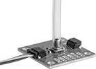
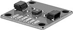
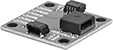
Motion-Sensing Modules for Development Boards
Modules with Adjustable Infrared Sensor
 |
Sensing Distance, m | Field of View | Input Voltage, V DC | Connection Method | Lg. | Wd. | Each | |||
|---|---|---|---|---|---|---|---|---|---|
| 2 to 6 | 110° | 5 to 12 | Solder | 1 1/4" | 1" | 8194N13 | 000000 | ||
Modules with Fixed Infrared Sensor
 |
Modules with a fixed infrared motion and thermal sensor can detect if a person is moving or even just present within the sensing distance. That means you could use them to automate lighting in an office where workers are sitting still. To connect them to your device, solder on wires or headers. For a solderless connection, use a Qwiic cord.
Output Data | |||||||||||||||
|---|---|---|---|---|---|---|---|---|---|---|---|---|---|---|---|
Sensing Distance, m | Field of View | Accuracy | Resolution, bit | Freq., Hz | Temp. Range, ° F | Input Voltage, V DC | I2C Address | Connection Method | No. of Qwiic Connections | Lg. | Wd. | Each | |||
I²C Communication Protocol—Qwiic Connection | |||||||||||||||
| 4 | 80° | ±0.3° C | 16 | 30 | -40 to 185 | 1.7 to 3.6 | 0x5A | Solder | 2 | 1" | 1" | 8194N12 | 000000 | ||
Circuit Board Voltage Regulators Assortments
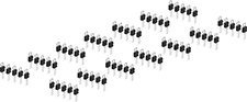 |
Safely power low-voltage components in circuits with a high-voltage source. These regulators turn high-voltage inputs into lower, more stable outputs.
Adjustable Output Voltage—Regulators with an adjustable output voltage let you fine-tune the output to best fit your circuit. To adjust the output voltage, connect them to two resistors (not included). The resistance values determine your output voltage.
Terminal | ||||||||||||||
|---|---|---|---|---|---|---|---|---|---|---|---|---|---|---|
Output Voltage, V DC | Max. Current, amp | Electronic Component Trade Size | Electronic Component Trade No. | No. of | Lg. | Material | For Hole Ctr.-to-Ctr. | Ht. | Wd. | Dp. | Each | |||
Fixed Output Voltage, Adjustable Output Voltage | ||||||||||||||
Positive, Negative | ||||||||||||||
| -15, -12, -9, -8, -6, -5, 1.25, 5, 6, 8, 9, 12, 15, 24, 37 | 1.5 | TO-220 | L7805, L7806, L7808, L7809, L7812, L7815, L7824, L7905, L7906, L7908, L7909, L7912, L7915, LM317 | 3 | 9/16" | Tin-Plated Copper | 0.1" | 5/8" | 13/32" | 3/16" | 7627N26 | 000000 | ||
Airflow Modules for Development Boards
Modules with Airflow Sensor
 |
Output Data | |||||||||||||||
|---|---|---|---|---|---|---|---|---|---|---|---|---|---|---|---|
Airflow Speed, mph | Airflow Speed Tolerance, mph | Resolution, bit | Freq., Hz | Measures | Temp. Range, ° F | Input Voltage, V DC | I2C Address | Connection Method | No. of Qwiic Connections | Lg. | Wd. | Each | |||
I²C Communication Protocol—Qwiic Connection | |||||||||||||||
| 0 to 33.6 | -1.68 to 1.68 | 12 | 8 | Airflow | 0 to 185 | 2.7 to 3.3 | 0x28 | Solder | 2 | 1" | 1" | 7135N11 | 000000 | ||
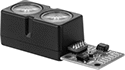
RFID Reader Kits for Development Boards
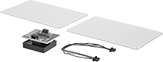 | 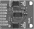 |
Reader |
Scan RFID cards when prototyping systems for item tracking and conveyor sorting. These readers scan one card at a time without requiring a direct line of sight, so they'll work in areas where bar code scanners can't. An LED and a buzzer indicate each successful scan. Readers connect to your development board with an included Qwiic cord that snaps into place, saving you the effort of soldering. If your board doesn’t have a Qwiic connection, choose a cord with a machine-pin plug. The two included RFID cards, as well as additional cards, have unique IDs and cannot be rewritten.
Sensing Distance—Sensing distance for your reader is reduced when cards are misaligned or scanned in hot or cold environments. The sensing distance in the table below represents typical factory conditions for the included card.
