


Filter by

Length

OD
Overall Length
Material
Construction
Maximum Torque
Ball Material
Bearing Material
Bearing Type
Number of Splines

For Rotary Motion
DFARS Specialty Metals
U.S.–Mexico–Canada Agreement (USMCA) Qualifying
Export Control Classification Number (ECCN)
REACH
RoHS
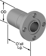
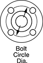
Mounted Linear Bearings for Ball Splines
 |
A flange with mounting holes makes it easy to attach a load to these bearings. Create a compact linear and rotary motion system for robots and other applications requiring complex, fast movements, by combining them with ball splines. These bearings move smoothly and precisely even at high speeds along ball splines while grooves on the ball spline transmit rotary power. Clip a retaining ring (not included) into the groove on these bearings to position them in your system.
Steel Bearings
 |  |  |
For 4 Splines |
Groove, mm | ||||||||||||||||||
|---|---|---|---|---|---|---|---|---|---|---|---|---|---|---|---|---|---|---|
For Spline Dia., mm | For No. of Splines | Overall Lg., mm | Flange OD, mm | Bolt Circle Dia., mm | OD, mm | Dynamic Load Cap., lb. | Static Load Cap., lb. | Max. Dynamic Torque, in·lbf | Max. Static Torque, in·lbf | Max. Temp., ° F | With Retaining Ring Grooves | Wd. | Dia. | No. of Mounting Holes | Each | |||
| 6 | 4 | 25 | 30 | 22 | 14 | 270 | 510 | 13 | 21 | 176 | Yes | 1.25 | 13.7 | 4 | 61145K41 | 0000000 | ||
| 8 | 4 | 25 | 32 | 24 | 16 | 325 | 645 | 18 | 32 | 176 | Yes | 1.25 | 15.6 | 4 | 61145K42 | 000000 | ||
| 10 | 4 | 33 | 42 | 32 | 21 | 610 | 1,100 | 38 | 72 | 176 | Yes | 1.65 | 20.5 | 4 | 61145K43 | 000000 | ||
| 13 | 4 | 36 | 43 | 33 | 24 | 600 | 1,050 | 185 | 346 | 176 | Yes | 1.3 | 22.7 | 4 | 61145K111 | 00000 | ||
| 16 | 4 | 50 | 50 | 40 | 31 | 1,350 | 2,500 | 531 | 973 | 176 | Yes | 1.6 | 29.4 | 4 | 61145K112 | 000000 | ||
| 18.2 | 4 | 60 | 51 | 40 | 32 | 1,750 | 2,500 | 734 | 1,177 | 176 | Yes | 3 | 31.3 | 4 | 61145K46 | 000000 | ||
| 20 | 4 | 63 | 58 | 45 | 35 | 2,000 | 3,650 | 929 | 1,717 | 176 | Yes | 2 | 33 | 4 | 61145K113 | 000000 | ||
| 23 | 4 | 70 | 60 | 47 | 37 | 2,750 | 3,600 | 1,433 | 2,115 | 176 | Yes | 3.5 | 36.1 | 4 | 61145K47 | 000000 | ||
| 25 | 4 | 71 | 65 | 52 | 42 | 2,850 | 5,250 | 1,672 | 3,062 | 176 | Yes | 2.5 | 39.5 | 4 | 61145K114 | 000000 | ||
| 28 | 4 | 80 | 70 | 54 | 45 | 4,150 | 5,200 | 2,557 | 3,646 | 176 | Yes | 4 | 43.9 | 4 | 61145K48 | 000000 | ||
| 30 | 4 | 80 | 75 | 60 | 47 | 4,150 | 5,200 | 2,716 | 3,885 | 176 | Yes | 3 | 44 | 4 | 61145K115 | 000000 | ||
| 37.4 | 4 | 100 | 90 | 72 | 60 | 6,900 | 8,400 | 5,637 | 7,806 | 176 | Yes | 5 | 58.6 | 4 | 61145K49 | 000000 | ||
| 40 | 4 | 100 | 100 | 82 | 64 | 6,900 | 8,400 | 5,964 | 8,266 | 176 | Yes | 4 | 60 | 4 | 61145K116 | 000000 | ||
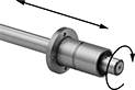
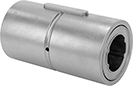
Keyless Locking Rigid Shaft Couplings for Overhung Loads
Steel
 |
For Shaft Dia. | Overall Lg. | OD | Max. Rotation Speed, rpm | Max. Torque, in·lbf | Fastener Tightening Torque, in·lbf | Overhung Load Cap., in·lbf | For Rotary Motion | Each | |||
|---|---|---|---|---|---|---|---|---|---|---|---|
For Keyed, Round, and Splined Shafts | |||||||||||
| 1 1/4" | 1 7/8" | 3" | 10,000 | 8,435 | 104 | 2,105 | Forward/Reverse, Start/Stop, Continuous | 3456N11 | 0000000 | ||
| 1 3/8" | 1 7/8" | 3" | 10,000 | 9,285 | 104 | 2,320 | Forward/Reverse, Start/Stop, Continuous | 3456N12 | 000000 | ||
| 1 1/2" | 2 3/16" | 3 3/4" | 8,000 | 17,160 | 264 | 4,290 | Forward/Reverse, Start/Stop, Continuous | 3456N13 | 000000 | ||
| 1 3/4" | 2 3/16" | 3 3/4" | 8,000 | 20,025 | 264 | 5,005 | Forward/Reverse, Start/Stop, Continuous | 3456N14 | 000000 | ||
| 2" | 2 11/16" | 4 7/16" | 7,700 | 32,685 | 264 | 8,170 | Forward/Reverse, Start/Stop, Continuous | 3456N15 | 000000 | ||
| 2 1/4" | 3 1/16" | 4 3/4" | 7,500 | 44,135 | 264 | 11,030 | Forward/Reverse, Start/Stop, Continuous | 3456N16 | 000000 | ||
| 2 1/2" | 3 1/16" | 4 3/4" | 7,500 | 49,040 | 264 | 12,260 | Forward/Reverse, Start/Stop, Continuous | 3456N17 | 000000 | ||
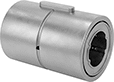
Linear Bearings for Ball Splines
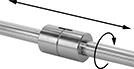 |
Combine these bearings with a ball spline to create a compact linear and rotary motion system for applications with fast, complex movements, such as robotics. These bearings move smoothly and precisely even at high speeds along ball splines while grooves on the ball spline transmit rotary power. Clip a retaining ring into the groove on these bearings to position them in your system. Use the keyway and included machine key for attaching your load.
Steel Bearings
 | |
For 4 Splines |
Groove, mm | Keyway, mm | ||||||||||||||||||
|---|---|---|---|---|---|---|---|---|---|---|---|---|---|---|---|---|---|---|---|
For Spline Dia., mm | For No. of Splines | Overall Lg., mm | OD, mm | Dynamic Load Cap., lb. | Static Load Cap., lb. | Max. Dynamic Torque, in·lbf | Max. Static Torque, in·lbf | Max. Temp., ° F | With Retaining Ring Grooves | Wd. | Dia. | Includes | Lg. | Wd. | Dp. | Each | |||
| 6 | 4 | 25 | 14 | 270 | 510 | 13 | 21 | 176 | Yes | 1.3 | 13.3 | Machine Key | 10.5 | 2.5 | 1.2 | 61145K31 | 000000 | ||
| 8 | 4 | 25 | 16 | 325 | 645 | 18 | 32 | 176 | Yes | 1.3 | 15.3 | Machine Key | 10.5 | 2.5 | 1.2 | 61145K32 | 00000 | ||
| 10 | 4 | 33 | 21 | 610 | 1,100 | 38 | 72 | 176 | Yes | 1.7 | 20 | Machine Key | 13 | 3 | 1.5 | 61145K33 | 00000 | ||
| 13 | 4 | 36 | 24 | 600 | 1,050 | 185 | 346 | 176 | Yes | 1.3 | 22.7 | Machine Key | 15 | 3 | 1.5 | 61145K12 | 00000 | ||
| 16 | 4 | 50 | 31 | 1,350 | 2,500 | 531 | 973 | 176 | Yes | 1.6 | 29.4 | Machine Key | 17.5 | 3.5 | 2 | 61145K13 | 00000 | ||
| 18.2 | 4 | 60 | 32 | 1,750 | 2,500 | 734 | 1,177 | 176 | Yes | 3.1 | 30.2 | Machine Key | 26 | 4 | 2.5 | 61145K36 | 000000 | ||
| 25 | 4 | 71 | 42 | 2,850 | 5,250 | 1,672 | 3,062 | 176 | Yes | 2.5 | 39.5 | Machine Key | 36 | 4 | 2.5 | 61145K15 | 000000 | ||
| 28 | 4 | 80 | 45 | 4,150 | 5,200 | 2,557 | 3,646 | 176 | Yes | 4.15 | 42.6 | Machine Key | 41 | 7 | 4 | 61145K38 | 000000 | ||
| 30 | 4 | 80 | 47 | 4,150 | 5,200 | 2,716 | 3,885 | 176 | Yes | 3 | 44 | Machine Key | 42 | 4 | 2.5 | 61145K16 | 000000 | ||
| 40 | 4 | 100 | 64 | 6,900 | 8,400 | 5,964 | 8,266 | 176 | Yes | 4 | 60 | Machine Key | 52 | 6 | 3.5 | 61145K17 | 000000 | ||
Stainless Steel Bearings
 | |
For 4 Splines |
Groove, mm | Keyway, mm | ||||||||||||||||||
|---|---|---|---|---|---|---|---|---|---|---|---|---|---|---|---|---|---|---|---|
For Spline Dia., mm | For No. of Splines | Overall Lg., mm | OD, mm | Dynamic Load Cap., lb. | Static Load Cap., lb. | Max. Dynamic Torque, in·lbf | Max. Static Torque, in·lbf | Max. Temp., ° F | With Retaining Ring Grooves | Wd. | Dia. | Includes | Lg. | Wd. | Dp. | Each | |||
| 6 | 4 | 25 | 14 | 270 | 510 | 13 | 21 | 176 | Yes | 0.6 | 13.4 | Machine Key | 10.5 | 2.5 | 1.2 | 61145K23 | 0000000 | ||
| 13 | 4 | 36 | 24 | 600 | 1,050 | 185 | 346 | 176 | Yes | 1.3 | 22.7 | Machine Key | 15 | 3 | 1.5 | 61145K26 | 000000 | ||
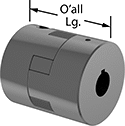
Spider Couplings
 |
With two hubs gripping a rubbery spider in the center, these couplings damp vibration and transfer torque while flexing to handle misaligned shafts. The metal hubs never touch each other, so there's no need for lubrication. Also known as Lovejoy® couplings. For a complete coupling, select two hubs and one spider or two hubs, one split spider, and one retaining ring. Choose components with the same trade size to ensure they'll fit together.
Hubs
 |
The metal body mounts onto shafts to transmit torque from one shaft to the other through the flexible center.
Splined—Grooves on the hub fit with splines on a shaft.
Iron—Best for dry environments, since moisture will cause these hubs to rust.
Clamp-On Shaft Mount—Grip shafts evenly without marring them and hold tighter than set screws. Tighten the clamping screws to secure.
OD | Shaft Coupling Trade Size | Overall Lg. | Shaft Mount Type | Choose a Shaft Dia. | Each | |||
|---|---|---|---|---|---|---|---|---|
Splined | ||||||||
Iron | ||||||||
| 2 7/64" | L090 | 2 3/16" | Clamp On | A (X 5/8", Y 0.509"), B (X 7/8", Y 0.754") | 9843T1 | 000000 | ||
| 2 7/64" | L095 | 2 9/16" | Clamp On | A (X 5/8", Y 0.509"), B (X 7/8", Y 0.754") | 9843T2 | 00000 | ||
| 2 17/32" | L099 | 2 7/8" | Clamp On | A (X 5/8", Y 0.509"), B (X 7/8", Y 0.754"), BB (X 1", Y 0.877") | 9843T3 | 00000 | ||
| 2 17/32" | L100 | 3 1/2" | Clamp On | A (X 5/8", Y 0.509"), B (X 7/8", Y 0.754"), BB (X 1", Y 0.877") | 9843T4 | 00000 | ||
| 3 21/64" | L110 | 4 1/4" | Clamp On | A (X 5/8", Y 0.509"), B (X 7/8", Y 0.754"), BB (X 1", Y 0.877"), C (X 1 1/4", Y 1.087") | 9843T5 | 000000 | ||
| 3 3/4" | L150 | 4 1/2" | Clamp On | A (X 5/8", Y 0.509"), B (X 7/8", Y 0.754"), BB (X 1", Y 0.877"), C (X 1 1/4", Y 1.087"), D (X 1 3/4", Y 1.506"), E (X 1 3/4", Y 1.506") | 9843T6 | 000000 | ||
Splined-to-Keyed Spider Couplings
 | 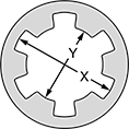 |
Diameter |
Connect heavy duty machinery with splined shafts to components with keyed shafts—a hydraulic pump and an electric motor, for example. A central spider damps vibration, absorbs shock, and adjusts for misalignment. No lubrication required. For a complete coupling, select two hubs and one spider. Choose components of the same trade size to ensure they'll fit together.
Hubs
 |
The metal body mounts onto shafts to transmit torque from one shaft to the other through the flexible center.
Iron—Best for dry environments, since moisture will cause these hubs to rust.
Hubs | Keyed Hubs | |||||||||
|---|---|---|---|---|---|---|---|---|---|---|
OD | Shaft Coupling Trade Size | Overall Lg. | Choose a Shaft Dia. | Each | Choose a Shaft Diameter | Each | ||||
Iron | ||||||||||
| 2 7/64" | L090 | 2 3/16" | A (X 5/8", Y 0.509"), B (X 7/8", Y 0.754") | 9843T101 | 000000 | 3/8", 1/2", 5/8", 3/4", 1" | 3451N801 | 000000 | ||
| 2 17/32" | L099 | 2 7/8" | A (X 5/8", Y 0.509"), B (X 7/8", Y 0.754"), BB (X 1", Y 0.877") | 9843T301 | 00000 | 1/2", 5/8", 3/4", 1", 1 1/8" | 3451N802 | 00000 | ||
| 3 3/4" | L150 | 4 1/2" | A (X 5/8", Y 0.509"), B (X 7/8", Y 0.754"), BB (X 1", Y 0.877"), C (X 1 1/4", Y 1.087"), D (X 1 3/4", Y 1.506"), E (X 1 3/4", Y 1.506") | 9843T601 | 000000 | 5/8", 3/4", 1", 1 1/8", 1 1/4", 1 1/2", 1 3/4" | 3451N803 | 00000 | ||
