


Drain, Waste, and Vent PVC Clamp-On Pipe Fittings for Water
 |
Clamp-On Pipe End |
For Pipe Size | For Pipe OD | Material | Max. Pressure @ Temp. | Clamp Material | Each | |||
|---|---|---|---|---|---|---|---|---|
Clamp-On Pipe End | ||||||||
| 5 | 5 5/8" | PVC | 4 psi @ 72° F | 300 Series Stainless Steel | 4511K111 | 000000 | ||
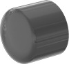
Tapered Caps
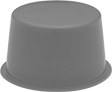 |
For OD | For Pipe Size | Inside Ht. | Flexibility | Max. Temp., ° F | Color | Pkg. Qty. | Pkg. | |||
|---|---|---|---|---|---|---|---|---|---|---|
Polyethylene | ||||||||||
| 5.21" to 5.37" | 5 | 7/8" | Flexible | 150 | Red | 10 | 4491K115 | 000000 | ||
Hollow Tapered Plugs
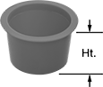 |
For ID | For Pipe Size | Ht. | Max. Temp., ° F | Color | Flange Dia. | Pkg. Qty. | Pkg. | |||
|---|---|---|---|---|---|---|---|---|---|---|
Polyethylene | ||||||||||
| 4.99" to 5.2" | 5 | 1" | 150 | Red | 5 5/8" | 10 | 4491K96 | 000000 | ||
Wing-Nut Expansion Plugs
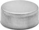
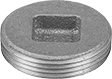
Metal Round Caps
Standard-Wall Plastic Pipe Fittings for Water
 |
Cement Socket Female |
Pipe Size | Pipe Schedule | Material | Color | Max. Pressure @ Temp. | Food Industry Std. | Each | |||
|---|---|---|---|---|---|---|---|---|---|
Cement Socket Female | |||||||||
| 5 | 40 | PVC | White | Not Rated | NSF/ANSI 61 | 4880K298 | 000000 | ||
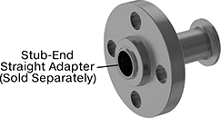
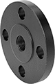
Low-Pressure Iron and Steel Unthreaded Pipe Flanges
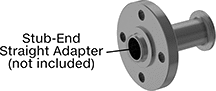 |
Stub-End Flange with Straight Adapter: Front |
 |  |  |  |  |  |  |
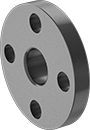
Butt Weld: Front | Butt Weld: Raised Surface on Back | Slip-On Weld: Front | Slip-On Weld: Raised Surface on Back | Socket Connect: Front | Socket Connect: Raised Surface on Back | Stub End: Flat Surface on Back |
Pipe Size | Bolt Hole | ||||||||||||||
|---|---|---|---|---|---|---|---|---|---|---|---|---|---|---|---|
(A) | (B) | Flanged Connection Surface (B) | Flange OD | For Bolt Dia. | Dia. | No. Of | Bolt Circle Dia. | Pressure Class | Material | Max. Pressure @ Temp. | Max. Steam Pressure @ Temp. | Each | |||
Butt Weld | |||||||||||||||
| 5 | 5 | Raised | 10" | 3/4" | 7/8" | 8 | 8 1/2" | 150 | Steel | 285 psi @ 72° F | 150 psi @ 300° F | 68095K413 | 000000 | ||
Slip-On Weld Female | |||||||||||||||
| 5 | 5 | Raised | 10" | 3/4" | 7/8" | 8 | 8 1/2" | 150 | Steel | 285 psi @ 72° F | 150 psi @ 300° F | 68095K396 | 00000 | ||
Socket-Connect Female | |||||||||||||||
| 5 | 5 | Raised | 10" | 3/4" | 7/8" | 8 | 8 1/2" | 150 | Steel | 285 psi @ 72° F | 150 psi @ 300° F | 68095K399 | 00000 | ||
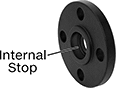
Stub-End Female | |||||||||||||||
| 5 | 5 | Flat | 10" | 3/4" | 7/8" | 8 | 8 1/2" | 150 | Steel | 285 psi @ 72° F | 150 psi @ 300° F | 68095K419 | 00000 | ||
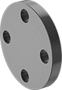
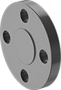
 |  |
Front | Raised Surface on Back |
Bolt Hole | ||||||||||||||
|---|---|---|---|---|---|---|---|---|---|---|---|---|---|---|
Pipe Size | Flanged Connection Surface | Flange OD | For Bolt Dia. | Dia. | No. Of | Bolt Circle Dia. | Pressure Class | Material | Max. Pressure @ Temp. | Max. Steam Pressure @ Temp. | Each | |||
Flanged | ||||||||||||||
| 5 | Raised | 10" | 3/4" | 7/8" | 8 | 8 1/2" | 150 | Steel | 285 psi @ 72° F | 150 psi @ 300° F | 68095K416 | 000000 | ||
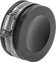
Rubber Drain Pipe Plugs
 |
Plugs |
For Pipe Size | For Pipe OD | Max. Water Back Pressure, ft. of head | Max. Air Back Pressure | Material | Each | |||
|---|---|---|---|---|---|---|---|---|
Clamp-On Female | ||||||||
| 5 | 5.30" to 5.62" | 10 | Not Rated | Neoprene | 2394K15 | 000000 | ||
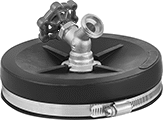 |
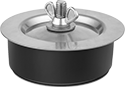
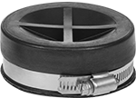
Plugs with Faucet |
For Pipe Size | For Pipe OD | Max. Water Back Pressure | Max. Air Back Pressure | Temp. Range, ° F | Material | Each | |||
|---|---|---|---|---|---|---|---|---|---|
Clamp-On Female | |||||||||
| 5 | 5.25" to 5.61" | Not Rated | Not Rated | -40 to 180 | Neoprene | 2394K108 | 000000 | ||
Adhesive-Back Caps for Pipe Flanges
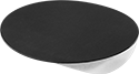 |
For Pipe Size | For OD | Flexibility | Max. Temp., ° F | Color | Adhesive Material | Pkg. Qty. | Pkg. | |||
|---|---|---|---|---|---|---|---|---|---|---|
Polyethylene | ||||||||||
For ANSI Flanges | ||||||||||
| 5 | 7 5/16" | Rigid | 160 | Black | Rubber | 3 | 3445T22 | 000000 | ||
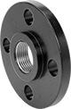
Low-Pressure Galvanized Iron and Steel Threaded Pipe Flanges
%20--%3e%3cg%3e%3cg%20id='Layer_1'%3e%3cpath%20class='cls-1'%20d='M68,27.2c-14.6,0-26.4,11.7-26.4,26.3,0,7,2.8,13.7,7.7,18.7v44.8l18.8-16.1,18.7,16.1v-44.9c10.3-10.3,10.3-27,0-37.3-5-4.9-11.7-7.7-18.7-7.7h0ZM81.3,105l-13.2-11.4-13.2,11.4v-28.7c8.2,4.8,18.3,4.8,26.5,0v28.7ZM76.2,70.8c-5.2,2.5-11.2,2.5-16.4,0-9.5-4.5-13.5-15.9-9-25.4,4.5-9.5,15.9-13.5,25.4-9,9.5,4.5,13.5,15.9,9,25.4-1.9,4-5.1,7.1-9,9Z'/%3e%3cpath%20class='cls-2'%20d='M5.8,95.5c-1.2,0-2.1-1-2.1-2.1,0,0,0,0,0,0V29.4h20.9c2.1,0,3.8-1.7,3.8-3.8V3.7c.2,0,.4,0,.5,0h37.5c1.2,0,2.1,1,2.1,2.1v18.6c1.2,0,2.5.1,3.7.3V5.8C72.2,2.6,69.6,0,66.4,0H28.9c-1.5,0-3,.6-4.1,1.7h-.1c0,.1-23,23.2-23,23.2-1.1,1.1-1.7,2.6-1.7,4.1v64.3c0,3.2,2.6,5.8,5.8,5.8h41.7v-3.7H5.8ZM24.7,7.1v18.7H6L24.7,7.1Z'/%3e%3c/g%3e%3c/g%3e%3c/svg%3e)
 |  |
Front | Raised Surface on Back |
Pipe Size | Bolt Hole | ||||||||||||||
|---|---|---|---|---|---|---|---|---|---|---|---|---|---|---|---|
(A) | (B) | Flanged Connection Surface (B) | Flange OD | For Bolt Dia. | Dia. | No. Of | Bolt Circle Dia. | Pressure Class | Material | Max. Pressure @ Temp. | Max. Steam Pressure @ Temp. | Each | |||
NPT Female | |||||||||||||||
| 5 | 5 | Raised | 10" | 3/4" | 7/8" | 8 | 8 1/2" | 150 | Galvanized Steel | 285 psi @ 72° F | 150 psi @ 300° F | 7551K129 | 0000000 | ||
Thick-Wall Plastic Pipe Fittings for Water
 |
Cement Socket Female |
Pipe Size | Pipe Schedule | Material | Color | Max. Pressure @ Temp. | Food Industry Std. | Each | |||
|---|---|---|---|---|---|---|---|---|---|
Cement Socket Female | |||||||||
| 5 | 80 | PVC | Dark Gray | Not Rated | NSF/ANSI 61 | 4881K017 | 0000000 | ||
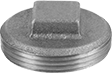
Brass and Bronze Threaded Cleanout Plugs
Thick-Wall Plastic Pipe Flanges for Water
Pipe Size | Bolt Hole | ||||||||||||||
|---|---|---|---|---|---|---|---|---|---|---|---|---|---|---|---|
(A) | (B) | Flanged Connection Surface (B) | Flange OD | For Bolt Dia. | Dia. | No. Of | Bolt Circle Dia. | Pressure Class | Material | Color | Food Industry Std. | Each | |||
Cement Socket Female | |||||||||||||||
| 5 | 5 | Raised | 10 3/16" | 3/4" | 7/8" | 8 | 8 1/2" | 150 | PVC | Dark Gray | NSF/ANSI 61 | 4881K101 | 0000000 | ||
Pipe Size | Bolt Hole | ||||||||||||||
|---|---|---|---|---|---|---|---|---|---|---|---|---|---|---|---|
(A) | (B) | Flanged Connection Surface (B) | Flange OD | For Bolt Dia. | Dia. | No. Of | Bolt Circle Dia. | Pressure Class | Material | Color | Food Industry Std. | Each | |||
Cement Socket Female | |||||||||||||||
| 5 | 5 | Raised | 10 1/8" | 3/4" | 7/8" | 8 | 8 1/2" | 150 | PVC | Dark Gray | NSF/ANSI 61 | 4881K104 | 000000 | ||
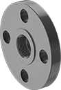
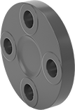 |  |
Front | Back |
Bolt Hole | ||||||||||||||
|---|---|---|---|---|---|---|---|---|---|---|---|---|---|---|
Pipe Size | Flanged Connection Surface | Flange OD | For Bolt Dia. | Dia. | No. Of | Bolt Circle Dia. | Pressure Class | Material | Color | Food Industry Std. | Each | |||
Flanged | ||||||||||||||
| 5 | Flat | 10 1/16" | 3/4" | 7/8" | 8 | 8 1/2" | 150 | PVC | Dark Gray | NSF/ANSI 61 | 4881K107 | 0000000 | ||
High-Pressure Iron and Steel Unthreaded Pipe Flanges
 |  |  |  |
Butt Weld (Front) | Butt Weld (Raised Surface on Back) | Slip-On Weld (Front) | Slip-On Weld (Raised Surface on Back) |
 |  |  |  |
Socket Connect (Front) | Socket-Connect (Raised Surface on Back) | Stub-End (Front) | Stub-End (Flat Surface on Back) |
Pipe Size | Bolt Hole | ||||||||||||||
|---|---|---|---|---|---|---|---|---|---|---|---|---|---|---|---|
(A) | (B) | Flanged Connection Surface (B) | Flange OD | For Bolt Dia. | Dia. | No. Of | Bolt Circle Dia. | Pressure Class | Material | Max. Pressure @ Temp. | Max. Steam Pressure @ Temp. | Each | |||
Butt Weld | |||||||||||||||
| 5 | 5 | Raised | 11" | 3/4" | 7/8" | 8 | 9 1/4" | 300 | Steel | 600 psi @ 72° F | 300 psi @ 300° F | 6806K344 | 0000000 | ||
Slip-On Weld Female | |||||||||||||||
| 5 | 5 | Raised | 11" | 3/4" | 7/8" | 8 | 9 1/4" | 300 | Steel | 600 psi @ 72° F | 300 psi @ 300° F | 6806K337 | 000000 | ||
Socket-Connect Female | |||||||||||||||
| 5 | 5 | Raised | 11" | 3/4" | 7/8" | 8 | 9 1/4" | 300 | Steel | Not Rated | Not Rated | 6806K341 | 000000 | ||
Stub-End Female | |||||||||||||||
| 5 | 5 | Flat | 11" | 3/4" | 7/8" | 8 | 9 1/4" | 300 | Steel | 600 psi @ 72° F | 300 psi @ 300° F | 6806K351 | 000000 | ||
 |  |
Front | Raised Surface on Back |
Bolt Hole | ||||||||||||||
|---|---|---|---|---|---|---|---|---|---|---|---|---|---|---|
Pipe Size | Flanged Connection Surface | Flange OD | For Bolt Dia. | Dia. | No. Of | Bolt Circle Dia. | Pressure Class | Material | Max. Pressure @ Temp. | Max. Steam Pressure @ Temp. | Each | |||
Flanged | ||||||||||||||
| 5 | Raised | 11" | 3/4" | 7/8" | 8 | 9 1/4" | 300 | Steel | 600 psi @ 72° F | 300 psi @ 300° F | 6806K347 | 0000000 | ||
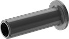 |
Straight Adapter |
Pipe Size | Flange OD | Construction | Pipe Schedule | Finished Material | Each | ||
|---|---|---|---|---|---|---|---|
| 5 | 7 5/16" | Seamless | 80 | Steel | 4981T311 | 0000000 |
Low-Pressure Iron and Steel Threaded Pipe Flanges
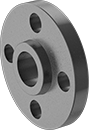
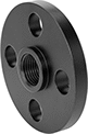 |  |
Front | Raised Surface on Back |
Pipe Size | Bolt Hole | ||||||||||||||
|---|---|---|---|---|---|---|---|---|---|---|---|---|---|---|---|
(A) | (B) | Flanged Connection Surface (B) | Flange OD | For Bolt Dia. | Dia. | No. Of | Bolt Circle Dia. | Pressure Class | Material | Max. Pressure @ Temp. | Max. Steam Pressure @ Temp. | Each | |||
NPT Female | |||||||||||||||
| 5 | 5 | Raised | 10" | 3/4" | 7/8" | 8 | 8 1/2" | 150 | Steel | 285 psi @ 72° F | 230 psi @ 300° F | 68095K222 | 000000 | ||
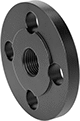
 |  |  |
Reducing Flange | Raised Surface on Back | Front |
Bolt Hole | |||||||||||||||
|---|---|---|---|---|---|---|---|---|---|---|---|---|---|---|---|
Pipe Size (A) | For Flange Pipe Size (B) | Flanged Connection Surface (B) | Flange OD | For Bolt Dia. | Dia. | No. Of | Bolt Circle Dia. | Pressure Class | Material | Max. Pressure @ Temp. | Max. Steam Pressure @ Temp. | Each | |||
NPT Female | |||||||||||||||
| 5 | 6 | Raised | 11" | 3/4" | 7/8" | 8 | 9 1/2" | 150 | Steel | 285 psi @ 72° F | 230 psi @ 300° F | 1802N48 | 0000000 | ||
Expansion Plugs with Bypass
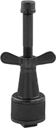 | 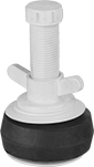 |
Style C | Style D |
For Pipe | Max. Back Pressure | Material | Bypass | |||||||||||
|---|---|---|---|---|---|---|---|---|---|---|---|---|---|---|
Size | ID | Air | Water, ft. of head | Overall Ht. | Temp. Range, ° F | Seal | Bypass Cap | Pipe Size | Thread Type | Gender | Each | |||
Style C | ||||||||||||||
Iron Stem | ||||||||||||||
| 5 | 4.50" to 5.00" | Not Rated | 23 | 12 5/8" | 30 to 150 | Natural Rubber | Metal | 1/2 | NPT | Male | 2644K24 | 000000 | ||
Style D | ||||||||||||||
Plastic Stem | ||||||||||||||
| 5 | 4.72" to 5.37" | 12 psi | 27 | 4 1/2" | -40 to 180 | Natural Rubber | Plastic | 1/2 | NPT | Male | 2566K41 | 00000 | ||
Air-Inflatable Plugs
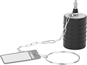 |
Style C |
|
Style C |
For Pipe | Deflated | Max. Back Pressure | ||||||||||||
|---|---|---|---|---|---|---|---|---|---|---|---|---|---|---|
Style | Size | ID | Dia. | Ht. | Chain Lg. | Air, psi | Water, ft. of head | Req. Inflation Pressure, psi | Temp. Range, ° F | Seal Material | Body Texture | Each | ||
| C | 5 | 4.60" to 5.25" | 4 1/2" | 7 3/4" | 12" | 13 | 30 | 30 | -20 to 125 | Natural Rubber | Ribbed | 3058K13 | 000000 | |
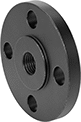
FM-Approved Low-Pressure Iron and Steel Threaded Pipe Flanges
 |
Front |
Pipe Size | Bolt Hole | ||||||||||||||
|---|---|---|---|---|---|---|---|---|---|---|---|---|---|---|---|
(A) | (B) | Flanged Connection Surface (B) | Flange OD | For Bolt Dia. | Dia. | No. Of | Bolt Circle Dia. | Material | Max. Pressure @ Temp. | Max. Steam Pressure @ Temp. | Certification | Each | |||
NPT Female | |||||||||||||||
| 5 | 5 | Flat | 10" | 3/4" | 7/8" | 8 | 8 1/2" | Cast Iron | 125 psi @ 72° F | 125 psi @ 350° F | FM Approved, UL Listed | 68185K131 | 0000000 | ||
High-Pressure Iron and Steel Threaded Pipe Flanges
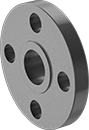
 |  |
Front | Raised Surface on Back |
Pipe Size | Bolt Hole | ||||||||||||||
|---|---|---|---|---|---|---|---|---|---|---|---|---|---|---|---|
(A) | (B) | Flanged Connection Surface (B) | Flange OD | For Bolt Dia. | Dia. | No. Of | Bolt Circle Dia. | Pressure Class | Material | Max. Pressure @ Temp. | Max. Steam Pressure @ Temp. | Each | |||
NPT Female | |||||||||||||||
| 5 | 5 | Raised | 11" | 3/4" | 7/8" | 8 | 9 1/4" | 300 | Steel | 600 psi @ 72° F | 300 psi @ 300° F | 6806K222 | 0000000 | ||
