


Filter by
For Use With
Export Control Classification Number (ECCN)
DFARS Specialty Metals
Manufacturer Model Number
Torque
Hardness
Specifications Met
Manufacturer
CAT 40 Taper End Mill Holders
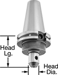 |
Securely grip end mills in machines with a CAT 40 taper spindle. Holders have threads on the tapered end to hold retention knobs that fit your machine.
Shank Thread | Head | ||||||||||
|---|---|---|---|---|---|---|---|---|---|---|---|
For End Mill Shank Dia. | For No. of End Mill Milling Ends | Size | Gender | Dia. | Lg. | Material | Fabrication | Includes | Each | ||
| 1/8" | 1, 2 | 5/8"-11 | Female | 3/4" | 2 3/8" | Steel | Heat Treated | Set Screws | 28745A118 | 0000000 | |
| 3/16" | 1, 2 | 5/8"-11 | Female | 3/4" | 2 1/2" | Steel | Heat Treated | Set Screws | 28745A122 | 000000 | |
| 1/4" | 1, 2 | 5/8"-11 | Female | 51/64" | 2 1/2" | Steel | Heat Treated | Set Screws | 28745A125 | 000000 | |
| 3/8" | 1, 2 | 5/8"-11 | Female | 1" | 2 1/2" | Steel | Heat Treated | Set Screws | 28745A132 | 000000 | |
| 1/2" | 1, 2 | 5/8"-11 | Female | 1 3/8" | 2 1/2" | Steel | Heat Treated | Set Screws | 28745A136 | 000000 | |
| 1/2" | 1, 2 | 5/8"-11 | Female | 1 3/8" | 4" | Steel | Heat Treated | Set Screws | 28745A137 | 000000 | |
| 5/8" | 1, 2 | 5/8"-11 | Female | 1 21/32" | 3" | Steel | Heat Treated | Set Screws | 28745A141 | 000000 | |
| 3/4" | 1, 2 | 5/8"-11 | Female | 1 3/4" | 3" | Steel | Heat Treated | Set Screws | 28745A145 | 000000 | |
| 1" | 1, 2 | 5/8"-11 | Female | 2 3/8" | 4" | Steel | Heat Treated | Set Screws | 28745A153 | 000000 | |
| 1 1/4" | 1, 2 | 5/8"-11 | Female | 2 1/2" | 4" | Steel | Heat Treated | Set Screws | 28745A156 | 000000 | |
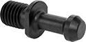
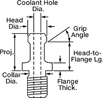
CAT Taper Retention Knobs
 |
 |  |
Knob | Knob with Pilot |
Lock tool holders in place on CNC machines with CAT taper spindles when milling, drilling, and routing. All meet industrial standards for tensile and shear strength. These knobs are also known as pull studs. To ensure compatibility with your machine, compare the features on these knobs, such as the location of O-ring seals and the pilot design, to those on your current knob. Use a torque wrench with a retention knob socket or a changeable-head torque wrench to tighten them.
Knobs with a pilot ensure precise alignment between the tool holder and spindle, reducing vibration and runout. To upgrade a standard knob to one with a pilot, confirm that the pilot diameter is small enough to fit in your tool holder without touching the inner walls where the knob seats.
Flange O-Ring Included—Knobs with flange O-rings block external coolant from entering your machine spindle. Match the O-ring placement and style to your current setup to ensure optimal sealing and performance.
Grip Angle—Grip angle is the sloped part of the knob that the machine grips to secure the tool holder. A 15˚ grip angle is sometimes referred to as a 75˚ grip angle. A 30˚ grip angle is sometimes referred to as a 60˚ grip angle.
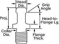
Grip Angle | Projection | Head Dia. | Pilot Dia. | Collar Dia. | Head-to-Flange Lg. | Flange Thk. | Torque Range, ft·lbf | O-Rings Included | Mfr. | Mfr. Model No. | Mfr. Equiv. Model No. | Specs. Met | JIS Specification | Each | |||
|---|---|---|---|---|---|---|---|---|---|---|---|---|---|---|---|---|---|
CAT 40 Machine Taper | |||||||||||||||||
5/8"-11 | |||||||||||||||||
| 15° | 1.023" | 0.748" | 0.64" | 0.49" | 0.787" | 0.157" | 45 to 55 | — | T.J. Davies | PS-470X15 | 711-25, 21006-15, 71125, C40-1500 ISO, RS4E-0114 | ISO 7388-3 | JIS B 6339 | 9496N14 | 000000 | ||
| 15° | 1.03" | 0.746" | — | 0.49" | 0.792" | 0.275" | 45 to 55 | — | T.J. Davies | PS-532X15 | 316-16, 4008TRK, 21007-15, 31616, C40-1500, RS4E-0212 | ISO 7388-3 | JIS B 6339 | 9496N16 | 00000 | ||
| 30° | 1.266" | 0.588" | — | 0.49" | 0.988" | 0.12" | 45 to 55 | — | T.J. Davies | PS-572X60 | 321-14, 4005TRK, 21118, 32114, C40-4500, RB4E-0001 | ISO 7388-3 | JIS B 6339 | 9496N27 | 00000 | ||
| 30° | 1.266" | 0.588" | — | 0.49" | 0.988" | 0.236" | 45 to 55 | — | T.J. Davies | PS-532X60 | 311-14A, 4014TRK, 21003-60, 31114A, C40S-6000, HPS-026, P40T-2CH, RB4E-0002 | ISO 7388-3 | JIS B 6339 | 9496N18 | 00000 | ||
| 45° | 0.64" | 0.74" | — | 0.49" | 0.44" | 0.12" | 45 to 55 | — | T.J. Davies | PS-475 | 111-23, 11123, 21003, C40-STD, P-40NTRK, RC4E-0002 | ASME B5.50, ISO 7388-3 | JIS B 6339 | 9496N15 | 00000 | ||
| 45° | 1.266" | 0.588" | — | 0.49" | 0.988" | 0.12" | 45 to 55 | — | T.J. Davies | PS-572X45 | 321-14, 4005TRK, 21118, 32114, C40-4500, RB4E-0001 | ISO 7388-3 | JIS B 6339 | 9496N26 | 00000 | ||
| 45° | 1.266" | 0.588" | — | 0.49" | 0.988" | 0.236" | 45 to 55 | — | T.J. Davies | PS-532X45 | 311-14, 4009TRK, 21003-45, 31114, C40S-4500, HPS-072, RS4E-0221 | ISO 7388-3 | JIS B 6339 | 9496N17 | 00000 | ||
| 45° | 1.266" | 0.591" | — | 0.512" | 0.99" | 0.236" | 44 to 59 | — | Lyndex Nikken | C40S-4500 | — | ASME B5.50 | — | 4403N16 | 00000 | ||
| 45° | 1.437" | 0.592" | — | 0.5" | 1.137" | 0.187" | 45 to 55 | — | T.J. Davies | PS-552 | 171-22, 17122, 21115, C400TRK, RS4E-0104 | ISO 7388-3 | JIS B 6339 | 9496N25 | 00000 | ||
| 90° | 1.266" | 0.588" | — | 0.49" | 0.988" | 0.236" | 45 to 55 | — | T.J. Davies | PS-532X90 | 311-14B, 4011TRK, 21003-90, 31114B, C40S-9000, HPS-014, HPS-C40-MAS-90, POM40CF, RB4E-0003 | ISO 7388-3 | JIS B 6339 | 9496N19 | 00000 | ||
| 90° | 1.266" | 0.588" | 0.64" | 0.49" | 0.988" | 0.236" | 45 to 55 | Flange O-Ring | T.J. Davies | PSO-532X90 | 21136-C, MAS P40T-3 | ISO 7388-3 | JIS B 6339 | 9496N21 | 00000 | ||
M16 × 2 mm | |||||||||||||||||
| 45° | 1.266" | 0.588" | — | 0.49" | 0.988" | 0.236" | 45 to 55 | — | T.J. Davies | PS-534X45 | 350-00V, 21106, 35000V, MH40TRK | ISO 7388-3 | JIS B 6339 | 9496N22 | 00000 | ||
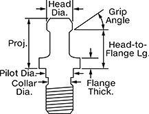
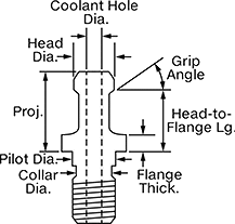
CAT Taper Retention Knobs with Coolant Hole
 |
 |  |
Knob | Knob with Pilot |
Lock tool holders in place on CNC machines with a through-spindle coolant (TSC) system. They fit machines with a CAT taper spindle. All meet industrial standards for tensile and shear strength. Also known as pull studs. Use a torque wrench with a retention knob socket or a changeable-head torque wrench to tighten them.
To ensure compatibility with your machine, compare the features on these knobs, such as the location of O-ring seals and the pilot design, to those on your current knob.
Knobs with a pilot ensure precise alignment between the tool holder and spindle, reducing vibration and runout. To upgrade a standard knob to one with a pilot, confirm that the pilot diameter is small enough to fit in your tool holder without touching the inner walls where the knob seats.
Flange O-Ring Included—Knobs with flange O-rings block external coolant from entering your machine spindle. Match the O-ring placement and style to your current setup to ensure optimal sealing and performance.
Ground Face—Knobs with a ground face have a tighter seal than those without one, which helps prevent coolant leaks.
Grip Angle—Grip angle is the sloped part of the knob that the machine grips to secure the tool holder. A 15˚ grip angle is sometimes referred to as a 75˚ grip angle. A 30˚ grip angle is sometimes referred to as a 60˚ grip angle.
Grip Angle | Projection | Head Dia. | Coolant Hole Diameter | Pilot Dia. | Collar Dia. | Head-to-Flange Lg. | Flange Thk. | Torque Range, ft·lbf | O-Rings Included | Features | Mfr. | Mfr. Model No. | Mfr. Equiv. Model No. | Specs. Met | JIS Specification | Each | |||
|---|---|---|---|---|---|---|---|---|---|---|---|---|---|---|---|---|---|---|---|
CAT 40 Machine Taper | |||||||||||||||||||
5/8"-11 | |||||||||||||||||||
| 15° | 1.023" | 0.746" | 0.264" | 0.64" | 0.49" | 0.787" | 0.157" | 45 to 55 | — | — | T.J. Davies | PSC-470X15 | 711-23, 4030TRK, 21006-15-C, 71123, C40-1500 ISOH, HPS-806U-1, RS4E-0114-C | ISO 7388-3 | JIS B 6339 | 9499N21 | 000000 | ||
| 15° | 1.023" | 0.746" | 0.265" | — | 0.49" | 0.787" | 0.157" | 45 to 55 | Head O-Ring in Coolant Hole | — | T.J. Davies | PSCO-470X15 | 711-22, 71122 | ISO 7388-3 | JIS B 6339 | 9499N22 | 00000 | ||
| 15° | 1.024" | 0.746" | 0.236" | 0.64" | 0.49" | 0.787" | 0.157" | 45 to 55 | — | — | T.J. Davies | PSC-572X15 MATS | 40PCMGH, 510-23, 51023, RS4E-0209C | ISO 7388-3 | JIS B 6339 | 9499N49 | 00000 | ||
| 15° | 1.024" | 0.747" | 0.236" | 0.64" | 0.49" | 0.787" | 0.157" | 45 to 55 | Flange O-Ring, Head O-Ring in Coolant Hole | — | T.J. Davies | PSCO-470X15A | 750-22-A, 21148-C, 75022A, HPS-806U-2, PMO40CMG, RS4E-0114-H | ISO 7388-3 | JIS B 6339 | 9499N23 | 00000 | ||
| 15° | 1.024" | 0.748" | 0.276" | — | 0.512" | 0.787" | 0.157" | 65 to 85 | — | Ground Face | Lyndex Nikken | C40-1500-MATS-EU | — | ASME B5.50 | — | 9499N11 | 00000 | ||
| 15° | 1.03" | 0.746" | 0.264" | — | 0.49" | 0.792" | 0.163" | 45 to 55 | — | — | T.J. Davies | PSC-572X15 | 21117-C | ISO 7388-3 | JIS B 6339 | 9499N48 | 00000 | ||
| 15° | 1.03" | 0.746" | 0.264" | — | 0.49" | 0.792" | 0.275" | 45 to 55 | Flange O-Ring | — | T.J. Davies | PSC-532X15 | 316-17, 4008TRKC, 21107-15C, 31617, C40-1500H, HPS-806U-1, RS4E-0212-C | ISO 7388-3 | JIS B 6339 | 9499N31 | 00000 | ||
| 15° | 1.03" | 0.746" | 0.264" | 0.64" | 0.49" | 0.792" | 0.236" | 45 to 55 | Flange O-Ring, Head O-Ring in Coolant Hole | — | T.J. Davies | PSCO-532X15A | C40-1500 MORI, HPS-C40-MORI-CO, PS-381E | ISO 7388-3 | JIS B 6339 | 9499N32 | 00000 | ||
| 15° | 1.03" | 0.748" | 0.276" | — | 0.512" | 0.793" | 0.276" | 44 to 59 | Flange O-Ring | Ground Face | Lyndex Nikken | C40-1500-EU | — | ASME B5.50 | — | 4403N11 | 00000 | ||
| 30° | 1.266" | 0.588" | 0.166" | — | 0.49" | 0.988" | 0.12" | 45 to 55 | — | — | T.J. Davies | PSC-572X60 | 21119-C, C40-6000H, RB4E-0002-C | ISO 7388-3 | JIS B 6339 | 9499N53 | 00000 | ||
| 30° | 1.266" | 0.588" | 0.166" | — | 0.49" | 0.988" | 0.236" | 45 to 55 | — | — | T.J. Davies | PSC-532X60 | 318-14A, 4014TRKC, 21003-60C, 31814A, C40S-6000H, HPS-026C, P40T-2CH, RB4E-0002-C | ISO 7388-3 | JIS B 6339 | 9499N35 | 00000 | ||
| 30° | 1.266" | 0.591" | 0.177" | — | 0.512" | 0.99" | 0.124" | 65 to 85 | — | Ground Face | Lyndex Nikken | C40-6000(H)-EU | — | ASME B5.50 | — | 9499N12 | 00000 | ||
| 45° | 0.64" | 0.74" | 0.157" | 0.64" | 0.49" | 0.44" | 0.12" | 45 to 55 | Flange O-Ring | — | T.J. Davies | PSC-471 | 21127-C, HPS-B64-1, PYN40CMG | ASME B5.50, ISO 7388-3 | JIS B 6339 | 9499N24 | 00000 | ||
| 45° | 0.64" | 0.74" | 0.157" | 0.64" | 0.49" | 0.44" | 0.12" | 45 to 55 | Flange O-Ring | — | T.J. Davies | PSC-473 | 327-16, 21128-C, 32716 | ASME B5.50, ISO 7388-3 | JIS B 6339 | 9499N26 | 00000 | ||
| 45° | 0.64" | 0.74" | 0.157" | 0.64" | 0.49" | 0.44" | 0.12" | 45 to 55 | Flange O-Ring | Ground Face | T.J. Davies | PSCG-471 | — | ASME B5.50, ISO 7388-3 | JIS B 6339 | 9499N25 | 00000 | ||
| 45° | 0.64" | 0.74" | 0.264" | — | 0.49" | 0.44" | 0.12" | 45 to 55 | — | — | T.J. Davies | PSC-475 | 111-22, 11122, 21003-C, C40-STDH, HPS-D72, P-40TRK, PYN40C, RC4E-0001 | ASME B5.50, ISO 7388-3 | JIS B 6339 | 9499N28 | 00000 | ||
| 45° | 0.64" | 0.74" | 0.264" | 0.64" | 0.49" | 0.44" | 0.12" | 45 to 55 | — | — | T.J. Davies | PSC-474 | 312-26, 21104-C, 31226, C40-STDH, HPS-G53, P40TRK, PYN40C, RS4E-0211-C | ASME B5.50, ISO 7388-3 | JIS B 6339 | 9499N27 | 00000 | ||
| 45° | 0.64" | 0.74" | 0.276" | — | 0.512" | 0.433" | 0.12" | 44 to 59 | — | Ground Face | Lyndex Nikken | C40-STD | — | ASME B5.50 | — | 4403N24 | 00000 | ||
| 45° | 1.266" | 0.588" | 0.166" | — | 0.49" | 0.988" | 0.12" | 45 to 55 | — | — | T.J. Davies | PSC-572X45 | 510-23, 21118-C, 51023, C40-4500H, RB4E-0001-C | ISO 7388-3 | JIS B 6339 | 9499N51 | 00000 | ||
| 45° | 1.266" | 0.588" | 0.166" | — | 0.49" | 0.988" | 0.236" | 45 to 55 | — | — | T.J. Davies | PSC-532X45 | 315-14, 4009TRKC, 21003-45C, 31514, C40S-4500H, HPS-072C, RS4E-0221-C | ISO 7388-3 | JIS B 6339 | 9499N33 | 00000 | ||
| 45° | 1.266" | 0.588" | 0.187" | 0.64" | 0.49" | 0.988" | 0.236" | 45 to 55 | — | — | T.J. Davies | PSCP-532X45 | MAS PT 1 403-1973 | ISO 7388-3 | JIS B 6339 | 9499N34 | 00000 | ||
| 45° | 1.266" | 0.591" | 0.177" | — | 0.512" | 0.99" | 0.236" | 44 to 59 | — | Ground Face | Lyndex Nikken | C40S-4500(H) | — | ASME B5.50 | JIS B 6339 | 4403N17 | 00000 | ||
| 45° | 1.268" | 0.588" | 0.118" | 0.64" | 0.49" | 0.99" | 0.126" | 45 to 55 | Flange O-Ring, Head O-Ring in Coolant Hole | — | T.J. Davies | PSC-572X45 HITA | 321-30, 32130, C40-HITACHI, PS-H27 | ISO 7388-3 | JIS B 6339 | 9499N52 | 00000 | ||
| 90° | 1.266" | 0.588" | 0.166" | — | 0.49" | 0.988" | 0.236" | 45 to 55 | — | — | T.J. Davies | PSC-532X90 | 350-30, 4001TRKC, 21003-90C, 35030, C40S-9000H, HPS-014C, HPS-C40-MAS-90-C, RB4E-0003-C | ISO 7388-3 | JIS B 6339 | 9499N36 | 00000 | ||
M16 × 2 mm | |||||||||||||||||||
| 45° | 0.64" | 0.74" | 0.264" | — | 0.49" | 0.44" | 0.12" | 45 to 55 | — | — | T.J. Davies | PSC-478 | 17836, A40TRK, B40-STDH, RS4M-0105 | ASME B5.50, ISO 7388-3 | JIS B 6339 | 9499N29 | 00000 | ||
Torque Wrenches for CNC Retention Knobs
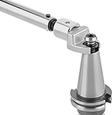 |  | |
Prevent damage to CNC spindles and tool holders when installing knobs. These wrenches torque retention knobs to manufacturer specs to avoid overtightening that can bend or misalign your setup. Set your torque and the wrench signals when it’s reached with an audible click and an impulse in the grip. All come with a calibration certificate, which includes test measurements that confirm accuracy.
For Machine Taper No. | Drive Size | Torque | Graduations | Opening Angle | Clockwise Accuracy | Mfr. | For Mfr. Model No. | Overall Lg. | Specs. Met | Certificate Type | Each | |||
|---|---|---|---|---|---|---|---|---|---|---|---|---|---|---|
Round Open End Heads—Nonratcheting | ||||||||||||||
ft·lbf, N-m | ||||||||||||||
| CAT 40 BT 40 | 3/4" | 30 ft·lbf to 150 ft·lbf 47 N-m to 197 N-m | 1 ft·lbf 1.4 N-m | Straight | ±4% | Lyndex Nikken | C40-1500 C40-1500(R) C40-1500-MORI C40-STD C40S-4500 C40S-4500(H) C40S-6000 PS-B64-1 B40-1500 B40-1500(R) B40-1500-MORI B40-4500 B40-4500(H) B40-FADAL | 21 1/4" | ASME B107.14M, ISO 6789 | Calibration Certificate with Test Data Traceable to DIN | 6643N2 | 0000000 | ||
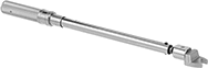
CNC Retention Knob Sockets
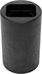 |  |
Install and remove retention knobs on machine tool holders with steep-taper shanks such as CAT and BT tapers. These sockets are precision machined to fit retention knobs, so you get a solid grip without harming the knob’s surfaces. That’s also why they’re made of hardened steel—they’re durable enough for frequent use yet softer than most knobs to prevent wear on the knob. With no damage to the retention knob, you’ll get a secure connection between the tool holder and your machine’s spindle and drawbar. Use a torque wrench (not included) to tighten the retention knob to your machine’s recommended torque.
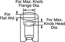
They’ll fit most knobs with the listed taper. To ensure compatibility, match your knob’s flat width, head diameter, and flange diameter to the socket dimensions.
For Max. Knob | ||||||||||||
|---|---|---|---|---|---|---|---|---|---|---|---|---|
For Machine Spindle Taper No. | For Flat Width | Head Dia. | Flange Dia. | Max. Torque, ft·lbf | Overall Lg. | OD | Material | Hardness | Each | |||
3/8" Square Drive | ||||||||||||
| BT 40, CAT 40, ISO 40 | 0.750" | 0.756" | 0.998" | 76 | 1 7/8" | 1 1/4" | Black-Oxide Hardened Steel | Rockwell C55 (Extra Hard) | 9501N12 | 000000 | ||
1/2" Square Drive | ||||||||||||
| BT 40, CAT 40, ISO 40 | 0.756" | 0.750" | 0.942" | 55 | 2 1/8" | 1 5/16" | Black-Oxide Hardened Steel | Rockwell C50 (Extra Hard) | 9501N15 | 00000 | ||
