


Filter by
Shaft Diameter
Construction
Maximum Torque

For Shaft Misalignment Type
Material

Overall Length
For Rotary Motion

Number of Teeth
Component

Torque
Set Screw Material
DFARS Specialty Metals
Export Control Classification Number (ECCN)
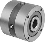
One-Way Clutches
Sprag Engagement—Flush Hub
 | 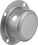 |
Covers |
 | 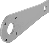 |
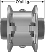
Torque Arm Shown Installed | Torque Arms |
Sprag clutches handle higher torque than roller clutches because they have more contact points. This makes them best for backstopping applications.
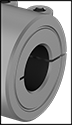
Clutches with a flush hub have a precision ground outer race, so they can be press fit directly into a component and positioned anywhere along the length of your shaft. They also have mounting holes on their face you can use to secure your component or an anti-rotation device, such as a torque arm, for a different backstopping setup.
Through Shaft—Through-shaft clutches regulate torque transmission between an input shaft and a mounted component.
Slip-Fit Shaft Mount—Clutches that mount to shafts with a slip fit must be secured with a shaft collar or in some other way that prevents them from moving along the length of your shaft.
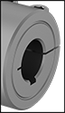
Covers—Covers protect you from rotating equipment when the clutch is mounted to the end of the shaft.
Torque Arms—Clutch torque arms work as an anchor for clutches in backstopping applications. Mount to the outer race of your clutch and a stationary piece of equipment.
Clutches | Covers | Torque Arms | |||||||||||||||
|---|---|---|---|---|---|---|---|---|---|---|---|---|---|---|---|---|---|
Max. Rotation Speed, rpm | Shaft | Clockwise or Counterclockwise Drive | |||||||||||||||
For Shaft Dia. | For Shaft Type | Max. Torque, ft·lbf | Inner-Race | Outer-Race | OD | Overall Lg. | Material | Keyway Wd. × Keyway Dp. | Mount Type | Each | Each | Each | |||||
Through Shaft | |||||||||||||||||
| 1 3/4" | Keyed | 2,250 | 2,200 | 750 | 5 3/8" | 3 3/4" | Steel | 3/8" × 3/16" | Slip Fit | 4550N25 | 000000000 | 4550N203 | 0000000 | 4550N303 | 0000000 | ||
High-Torque Flexible Shaft Couplings
 |  |
(Each Component Sold Separately) |
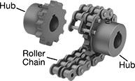
With a rugged roller-chain design, these couplings provide excellent torque and angular misalignment capacities. Lubrication is required. Fasten to your shaft by tightening the set screws, which bite into the shaft to hold it.
A complete coupling consists of two hubs and one roller chain (each component sold separately). Complete couplings meet ANSI B29.23M-1995.
Optional covers retain grease lubrication and provide protection from abrasion and corrosion.
Hubs | Steel Roller Chain | Orange Nylon Covers | |||||||||||||||||
|---|---|---|---|---|---|---|---|---|---|---|---|---|---|---|---|---|---|---|---|
Misalignment Capability | Roller Chain | ||||||||||||||||||
Overall Lg. | OD | OD with Cover | For Shaft Type | For Rotary Motion | For Shaft Dia. | Each | Max. Rotation Speed, rpm | Max. Torque, in·lbf | Parallel | Angular | No. | Standard | Each | Each | |||||
Steel Hubs | |||||||||||||||||||
| 3 29/64" | 5" | 6 3/8" | Keyed | Continuous | 1 3/4" | 6407K44 | 000000 | 3,000 | 10,900 | 0.012" | 1.5° | 60-2 | ANSI | 6407K54 | 000000 | 6407K74 | 0000000 | ||
High-Torque Set Screw Flexible Shaft Couplings
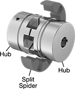 |  |
The thick split spider on these couplings takes on twice as much torque as standard split spiders, while a set screw holds the hubs in place on your shaft. Also known as jaw couplings, use them to connect motors to pumps, mixers, and other high-torque equipment. You don’t need to lubricate them.
For a complete coupling, you’ll need two hubs, one split spider, and a split spider cover (all sold separately).
Hubs attach to the end of your shaft.
Split spiders cushion between the two hubs to dampen vibration, reduce shocks, and handle shaft misalignment, extending the life of bearings, seals, and motors. You can replace them without having to remove the hubs or move your shaft and equipment around, which reduces the risk of needing to realign the shaft.
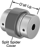
Split spider covers hold the spider in place.
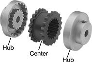
High-Speed Vibration-Damping Flexible Shaft Couplings
 |  |
(Each Component Sold Separately) |
Use these gear-shaped couplings for high-speed and high-torque applications. A rubber center allows flexing so couplings can take on multiple types of misalignment while damping vibration and shock. With no metal-to-metal contact, there’s no need for lubrication. Fasten to your shafts by tightening the set screws, which bite into the shaft to hold it.
A complete coupling consists of two hubs and one center (each component sold separately).
Hubs have a keyway, except hubs for 1⁄4" and 3⁄8" shaft dia. do not have a keyway.
Hubs | Shaft Coupling Centers | |||||||||||||||
|---|---|---|---|---|---|---|---|---|---|---|---|---|---|---|---|---|
Misalignment Capability | ||||||||||||||||
Overall Lg. | OD | For Rotary Motion | For Shaft Dia. | Each | Max. Rotation Speed, rpm | Max. Torque, in·lbf | Parallel | Angular | Axial | Temp. Range, ° F | Material | Each | ||||
Cast Iron Hubs | ||||||||||||||||
| 3 15/16" | 4 5/8" | Continuous | 1 3/4" | 6507K5 | 000000 | 5,250 | 725 | 0.02" | 1° | 0.125" | -30 to 275 | TPE | 6507K74 | 000000 | ||
| 5 1/16" | 6 23/64" | Continuous | 1 3/4" | 6507K7 | 000000 | 3,750 | 1,800 | 0.025" | 1° | 0.125" | -30 to 275 | TPE | 6507K76 | 00000 | ||
| 5 11/16" | 7 1/2" | Continuous | 1 3/4" | 6507K8 | 000000 | 3,600 | 2,875 | 0.025" | 1° | 0.125" | -30 to 275 | TPE | 6507K77 | 000000 | ||
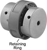
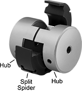
Set Screw Flexible Shaft Couplings
 |  |
Hubs, Split Spider, and Retaining Ring Shown Assembled | (Each Component Sold Separately) |
 |  |
Hubs and Spider Shown Assembled | (Each Component Sold Separately) |
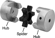
Each hub includes a set screw (unless noted), which bites into your shaft to hold the coupling in place. Also known as Lovejoy® couplings, these three-piece couplings have a spider-shaped cushion between two hubs to reduce shock and handle minor shaft misalignment.
A complete coupling consists of two hubs and one spider, or two hubs, one split spider, and one retaining ring (all components sold separately). Split spiders are easier to install and replace than standard spiders because there’s no need for tools or removing your hubs. Twist-lock them in place using a retaining ring.
Buna-N—Buna-N spiders provide good vibration damping and chemical resistance.
Hytrel—Hytrel spiders provide fair vibration damping and excellent chemical resistance.
Polyurethane Rubber—Polyurethane spiders and split spiders provide fair vibration damping and good chemical resistance.
Hubs | Buna-N Spiders | Hytrel Spiders | Polyurethane Spiders | |||||||||||||||||||||||||||||
|---|---|---|---|---|---|---|---|---|---|---|---|---|---|---|---|---|---|---|---|---|---|---|---|---|---|---|---|---|---|---|---|---|
Misalignment Capability | Misalignment Capability | Misalignment Capability | ||||||||||||||||||||||||||||||
Overall Lg. | OD | For Shaft Type | For Rotary Motion | For Shaft Dia. | Each | Max. Rotation Speed, rpm | Max. Torque, in·lbf | Parallel | Angular | Temp. Range, ° F | Spider Material | Each | Max. Rotation Speed, rpm | Max. Torque, in·lbf | Parallel | Angular | Temp. Range, ° F | Spider Material | Each | Max. Rotation Speed, rpm | Max. Torque, in·lbf | Parallel | Angular | Temp. Range, ° F | Spider Material | Each | ||||||
Iron Hubs | ||||||||||||||||||||||||||||||||
| 4 1/2" | 3 3/4" | Keyed | Forward/Reverse, Start/Stop | 1 3/4" | 6408K19 | 0000000 | 5,000 | 1,240 | 0.015" | 1° | -40 to 212 | Buna-N | 6408K81 | 000000 | 3,600 | 3,705 | 0.015" | 0.5° | -55 to 245 | Hytrel | 6408K98 | 0000000 | 3,600 | 1,860 | 0.015" | 1° | -30 to 160 | Polyurethane Rubber | 2410K19 | 0000000 | ||
| 4 7/8" | 4 1/2" | Keyed | Forward/Reverse, Start/Stop | 1 3/4" | 6408K21 | 000000 | 5,000 | 1,725 | 0.015" | 1° | -40 to 212 | Buna-N | 6408K82 | 00000 | 5,000 | 4,680 | 0.015" | 0.5° | -55 to 245 | Hytrel | 6408K99 | 000000 | — | — | — | — | — | — | ——— | 0 | ||
| 5 11/32" | 5" | Keyed | Forward/Reverse, Start/Stop | 1 3/4" | 6408K22 | 000000 | 4,200 | 2,340 | 0.015" | 1° | -40 to 212 | Buna-N | 6408K62 | 00000 | 4,200 | 6,225 | 0.015" | 0.5° | -55 to 245 | Hytrel | 6408K64 | 000000 | — | — | — | — | — | — | ——— | 0 | ||
Keyless Locking Rigid Shaft Couplings for Overhung Loads
Steel
 |
For Shaft Dia. | Overall Lg. | OD | Max. Rotation Speed, rpm | Max. Torque, in·lbf | Fastener Tightening Torque, in·lbf | Overhung Load Cap., in·lbf | For Rotary Motion | Each | |||
|---|---|---|---|---|---|---|---|---|---|---|---|
For Keyed, Round, and Splined Shafts | |||||||||||
| 1 3/4" | 2 3/16" | 3 3/4" | 8,000 | 20,025 | 264 | 5,005 | Forward/Reverse, Start/Stop, Continuous | 3456N14 | 0000000 | ||
Ultra-High-Torque Flexible Shaft Couplings
 |  |
(Each Component Sold Separately) |
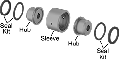
With a rigid gear design, these steel couplings transmit more torque than other couplings of the same size. Lubrication is required. To install, heat the hubs to expand them slightly and fit them onto the shaft. When they cool, hubs shrink to fit the shaft tightly.
A complete coupling consists of two hubs, one sleeve, and one seal kit (each component sold separately).
Hubs | Steel Sleeves | Seal Kits | ||||||||||||||||
|---|---|---|---|---|---|---|---|---|---|---|---|---|---|---|---|---|---|---|
Misalignment Capability | ||||||||||||||||||
Overall Lg. | OD | For Shaft Type | For Rotary Motion | For Shaft Dia. | Each | Max. Rotation Speed, rpm | Max. Torque, in·lbf | Parallel | Angular | Axial | Each | Includes | Each | |||||
Steel Hubs | ||||||||||||||||||
| 4 1/4" | 4 3/4" | Keyed | Continuous | 1 3/4" | 6454K15 | 0000000 | 4,200 | 20,200 | 0.007" | 1° | 0.03" | 6454K25 | 0000000 | Two Buna-N Rubber Lubrication Seals, Two Steel Snap Rings | 6454K35 | 000000 | ||
Quick-Disconnect (QD) Bushings
 |  |
Clamp-On Shaft Mount |
The screw connections on these bushings easily mate to compatible quick-disconnect sprockets and pulleys. Bushings fit quick-disconnect (QD) sprockets and pulleys of the same bushing trade number. As you tighten the included screws, the bushing grips the shaft and pulls it into the sprocket or pulley.
Keyway | ||||||||||
|---|---|---|---|---|---|---|---|---|---|---|
Overall Wd. | Wd. | Dp. | Fastener Tightening Torque, in·lbf | Material | Includes | For Shaft Dia. | Each | |||
Clamp-On Shaft Mount | ||||||||||
Bushing Trade Number SDS | ||||||||||
| 1 3/8" | 3/8" | 1/8" | 108 | Sintered Steel | Clamping Screws, Machine Key | 1 3/4" | 6086K326 | 000000 | ||
Bushing Trade Number SK | ||||||||||
| 1 15/16" | 3/8" | 3/16" | 180 | Sintered Steel | Clamping Screws | 1 3/4" | 6086K527 | 00000 | ||
Clamping Rigid Shaft Couplings
Steel
 |  |
For Keyed Shafts | For Round Shafts |
For Shaft Dia. | Overall Lg. | OD | Max. Rotation Speed, rpm | Max. Torque, in·lbf | For Rotary Motion | Each | |||
|---|---|---|---|---|---|---|---|---|---|
For Keyed Shafts | |||||||||
| 1 3/4" × 1 3/4" | 4 1/2" | 3 1/8" | 4,000 | 18,500 | Forward/Reverse, Start/Stop, Continuous | 61005K799 | 0000000 | ||
For Round Shafts | |||||||||
| 1 3/4" × 1 3/4" | 4 1/2" | 3 1/8" | 4,000 | 18,500 | Forward/Reverse, Start/Stop, Continuous | 61005K811 | 000000 | ||
303 Stainless Steel
| |
For Keyed Shafts | For Round Shafts |
Stainless steel couplings have excellent corrosion resistance.
For Shaft Dia. | Overall Lg. | OD | Max. Rotation Speed, rpm | Max. Torque, in·lbf | For Rotary Motion | Each | |||
|---|---|---|---|---|---|---|---|---|---|
For Keyed Shafts | |||||||||
| 1 3/4" × 1 3/4" | 4 1/2" | 3 1/8" | 4,000 | 5,500 | Forward/Reverse, Start/Stop, Continuous | 61005K822 | 0000000 | ||
For Round Shafts | |||||||||
| 1 3/4" × 1 3/4" | 4 1/2" | 3 1/8" | 4,000 | 5,500 | Forward/Reverse, Start/Stop, Continuous | 61005K833 | 000000 | ||
Two-Piece Rigid Shaft Couplings
Black-Oxide Steel
 |  |
For Keyed Shafts | For Round Shafts |
Steel couplings are stronger and handle higher torque loads than aluminum and stainless steel couplings.
For Keyed Shafts—Couplings for keyed shafts have keyways that are cut to standard ANSI dimensions, so they fit snugly on ANSI keyed shafts to eliminate slipping during starts and stops.
For Shaft Dia. | Overall Lg. | OD | Max. Rotation Speed, rpm | Max. Torque, in·lbf | For Rotary Motion | Each | |||
|---|---|---|---|---|---|---|---|---|---|
For Keyed Shafts | |||||||||
| 1 3/4" × 1 3/4" | 4 1/2" | 3 1/8" | 4,000 | 18,500 | Forward/Reverse, Start/Stop, Continuous | 60845K951 | 0000000 | ||
For Round Shafts | |||||||||
| 1 3/4" × 1 3/4" | 4 1/2" | 3 1/8" | 4,000 | 18,500 | Forward/Reverse, Start/Stop, Continuous | 60845K961 | 000000 | ||
Machinable-Bore Clamping Rigid Shaft Couplings
Steel
 |  |  |
For Keyed Shafts | For Round Shafts |
Steel couplings resist corrosion in dry environments.
For Keyed Shafts—Couplings for keyed shafts grip the shaft’s key to eliminate slipping. They handle higher torque than couplings for round shafts.
For Shaft Dia. | Overall Lg. | OD | Max. Rotation Speed | Max. Torque, in·lbf | For Rotary Motion | Each | |||
|---|---|---|---|---|---|---|---|---|---|
For Keyed Shafts | |||||||||
| 1 3/4" × 0.485" to 1.750" | 4 1/2" | 3" | Not Rated | 5,625 | Forward/Reverse, Start/Stop, Continuous | 3084K75 | 0000000 | ||
For Round Shafts | |||||||||
| 1 3/4" × 0.485" to 1.750" | 4 1/2" | 3" | Not Rated | 4,220 | Forward/Reverse, Start/Stop, Continuous | 3084K51 | 000000 | ||
303 Stainless Steel
| | |
For Keyed Shafts | For Round Shafts |
303 stainless steel couplings resist rusting from water. But, they won’t stand up to salt water or chloride.
For Shaft Dia. | Overall Lg. | OD | Max. Rotation Speed | Max. Torque, in·lbf | For Rotary Motion | Each | |||
|---|---|---|---|---|---|---|---|---|---|
For Round Shafts | |||||||||
| 1 3/4" × 0.485" to 1.750" | 4 1/2" | 3" | Not Rated | 2,900 | Forward/Reverse, Start/Stop, Continuous | 3084K63 | 0000000 | ||
Two-Piece Rigid Shaft Coupling Bridges
Cast Iron
 |
For Shaft Dia. | Overall Lg. | OD | Max. Rotation Speed, rpm | Max. Torque, in·lbf | For Rotary Motion | Each | |||
|---|---|---|---|---|---|---|---|---|---|
For Keyed Shafts | |||||||||
| 1 3/4" | 8 1/4" | 5 1/8" | 3,965 | 5,500 | Forward/Reverse, Start/Stop, Continuous | 6417K23 | 0000000 | ||
Shock-Absorbing Flexible Shaft Couplings
 | 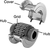 |
Components of a Coupling Shown Assembled | (Each Component Sold Separately) |
A strip of flexible spring steel wraps around the teeth of both hubs to absorb sharp, momentary load increases that can come from motor startups, emergency braking, or sudden impact with hard objects. When the shock load hits, the strip of spring steel (known as a grid) flexes to spread out the load. After the load passes, the grid straightens back out. They're commonly found in wire drawing and cutting machines, pulverizers, and mixers. Compared to spider couplings, jaw couplings, and other flexible shaft couplings, these handle higher torque while taking up less space. All have keyed bores to work with keyed shafts, which transmit higher torque with less slippage than round shafts.
A complete coupling consists of two hubs as well as a grid and cover assembly (all sold separately). The grid and cover assembly includes a spring steel grid, aluminum cover, rubber seals, and grease for lubrication. When ordering, please choose components that have the same manufacturer series number, otherwise the grid will not fit.
Hubs | Grid and Cover Assemblies | Replacement Grids | Replacement Seals | |||||||||||||||
|---|---|---|---|---|---|---|---|---|---|---|---|---|---|---|---|---|---|---|
Misalignment Capability | ||||||||||||||||||
Overall Lg. | OD | For Rotary Motion | Manufacturer Series | For Shaft Dia. | Each | Parallel | Angular | Max. Rotation Speed, rpm | Max. Torque, in·lbf | Each | Each | Each | ||||||
Black-Oxide Steel | ||||||||||||||||||
For Keyed Shafts | ||||||||||||||||||
| 4 7/8" | 3 19/32" | Continuous, Forward/Reverse, Start/Stop | Martin (1050T) | 1 3/4" | 3395N4 | 0000000 | 0.016" | 0.25° | 4,500 | 3,850 | 3395N123 | 0000000 | 3395N114 | 0000000 | 3395N132 | 000000 | ||
