


Filter by
System of Measurement
Outlet Thread Type
Maximum Flow Rate @ Pressure
Pipe Size
Inlet Thread Size
Outlet Pressure
Manufacturer
For Use With
Regulator Type
Outlet Connection
Maximum Pressure
Thread Size
Fitting Connection
DFARS Specialty Metals

About Air Preparation
Customize your air preparation system with dryers, filters, and other purifying parts.
SMC Modular Compressed Air Filter/Regulators for Particle Removal
10 Series—Metric Female Inlet × Metric Female Outlet
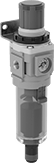 |  |
Clear Bowl | Opaque Bowl |
Aluminum Bowl—Aluminum bowls are stronger than plastic bowls, so they won't crack or shatter if dropped.
Automatic Drain—Bowls with an automatic drain periodically release condensate into the air, eliminating the need for manual emptying.
Joiner Clamps—Joiner clamps (sold separately) create compact, airtight connections between components. They come with mounting brackets.
Filter/Regulators | Elements | Replacement Filter Bowls | Joiner Clamps | Mounting Brackets | |||||||||||||||||
|---|---|---|---|---|---|---|---|---|---|---|---|---|---|---|---|---|---|---|---|---|---|
Overall | |||||||||||||||||||||
Inlet Thread Size | Outlet Thread Size | Max. Flow Rate @ Pressure | Pressure Regulation Range, psi | Max. Pressure, psi | Max. Temp., ° F | Removes Particle Size Down To, μm | Includes | Ht. | Wd. | Each | Each | Each | Each | Each | |||||||
AW10-A Series | |||||||||||||||||||||
Nylon Bowl—Clear with Automatic Drain | |||||||||||||||||||||
| M5 × 0.8 mm | M5 × 0.8 mm | 5.2 scfm @ 100 psi | 7.25 to 101 | 145 | 140 | 5 | Mounting Bracket | 4 1/4" | 1" | 8520T741 | 000000 | 6098K6 | 00000 | 3059N47 | 000000 | 8550T21 | 00000 | 8812K73 | 00000 | ||
Aluminum Bowl—Opaque with Automatic Drain | |||||||||||||||||||||
| M5 × 0.8 mm | M5 × 0.8 mm | 5.2 scfm @ 100 psi | 7.25 to 101 | 145 | 140 | 5 | Mounting Bracket | 4 1/4" | 1" | 8520T742 | 00000 | 6098K6 | 0000 | ——— | 0 | 8550T21 | 0000 | 8812K73 | 0000 | ||
Polycarbonate Bowl—Clear with Manual Drain | |||||||||||||||||||||
| M5 × 0.8 mm | M5 × 0.8 mm | 5.2 scfm @ 100 psi | 7.25 to 101 | 145 | 140 | 5 | Mounting Bracket | 4 1/4" | 1" | 6098K5 | 00000 | ——— | 0 | 3059N17 | 0000 | 8550T21 | 0000 | 8812K73 | 0000 | ||
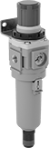
SMC Modular Compressed Air Regulators
Relieving Regulators
 |
Relieving regulators exhaust when the downstream pressure exceeds the set pressure.
Joiner Clamps—Joiner clamps (sold separately) create compact, airtight connections between components. These clamps come with mounting brackets.
Regulators | Joiner Clamps | ||||||||||||||||
|---|---|---|---|---|---|---|---|---|---|---|---|---|---|---|---|---|---|
Thread Size | Overall | ||||||||||||||||
Mfr. Series | Inlet | Outlet | Max. Flow Rate @ Pressure | Max. Pressure, psi | Gauge Included | Wd. | Ht. | Max. Temp., ° F | Includes | Regulating Accuracy | Choose Pressure Regulation, psi | Each | Each | ||||
Zinc Alloy Housing | |||||||||||||||||
10 Series—Metric Female Inlet × Metric Female Outlet | |||||||||||||||||
| AR10-A | M5 × 0.8 mm | M5 × 0.8 mm | 5 scfm @ 100 psi | 145 | Yes | 1" | 2 3/8" | 140 | Mounting Bracket | ±3 psi | 3 to 29, 7.25 to 100 | 8847N138 | 000000 | 8550T21 | 00000 | ||
Nonrelieving Regulators
|
Nonrelieving regulators do not exhaust excess downstream pressure. They’re often used to conserve air or to avoid contaminating a controlled area. To prevent pressure buildup, manually vent them or add a relief valve.
Joiner Clamps—Joiner clamps (sold separately) create compact, airtight connections between components. These clamps come with mounting brackets.
Regulators | Joiner Clamps | ||||||||||||||||
|---|---|---|---|---|---|---|---|---|---|---|---|---|---|---|---|---|---|
Thread Size | Overall | ||||||||||||||||
Mfr. Series | Inlet | Outlet | Max. Flow Rate @ Pressure | Max. Pressure, psi | Gauge Included | Wd. | Ht. | Max. Temp., ° F | Includes | Regulating Accuracy | Pressure Regulation, psi | Each | Each | ||||
Zinc Alloy Housing | |||||||||||||||||
10 Series—Metric Female Inlet × Metric Female Outlet | |||||||||||||||||
| AR10-A | M5 × 0.8 mm | M5 × 0.8 mm | 5 scfm @ 100 psi | 145 | Yes | 1" | 2 3/8" | 140 | Mounting Bracket | ±3 psi | 7.25 to 100 | 9926N331 | 000000 | 8550T21 | 00000 | ||
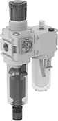
SMC Modular Compressed Air Filter/Regulator/Lubricators (FRLs)
Series No. 10—Metric Female Inlet and Outlet
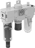 |  |
Inline with Clear Polycarbonate Bowl | Stacked with Clear Polycarbonate Bowl |
Inline Components—Inline FRLs are the standard design. Each part can be replaced or repaired on its own, which reduces maintenance costs.
Stacked Components—Stacked FRLs have a filter and regulator joined top-to-bottom and a lubricator on the side. They require less horizontal space than inline FRLs.
Joiner Clamps—Joiner clamps (sold separately) create compact, airtight connections between components. These clamps come with mounting brackets.
Compressed Air Filter/Regulator/Lubricators | Replacement Filter Bowls | Joiner Clamps | ||||||||||||||||
|---|---|---|---|---|---|---|---|---|---|---|---|---|---|---|---|---|---|---|
Thread Size | Overall | |||||||||||||||||
Mfr. Series | Inlet | Outlet | Max. Flow Rate @ Pressure | Max. Pressure, psi | Removes Particle Size Down To, μm | Pressure Regulation Range, psi | Includes | Lubricant Cap., fl. oz. | Ht. | Wd. | Each | Each | Each | |||||
Inline with Clear Polycarbonate Bowl and Automatic Drain | ||||||||||||||||||
| AC10-A | M5 × 0.8 mm | M5 × 0.8 mm | 6 scfm @ 100 psi | 145 | 5 | 7.25 to 123 | Mounting Bracket | 0.24 | 4" | 3 3/8" | 8492T111 | 000000 | 3059N47 | 000000 | 8550T21 | 00000 | ||
Stacked with Clear Polycarbonate Bowl and Automatic Drain | ||||||||||||||||||
| AC10-A | M5 × 0.8 mm | M5 × 0.8 mm | 6 scfm @ 100 psi | 145 | 5 | 7.25 to 123 | Mounting Bracket | 0.24 | 4" | 3 3/8" | 8492T113 | 00000 | 3059N47 | 00000 | 8550T21 | 0000 | ||
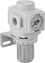
Manifold-Mount Compressed Air Regulators
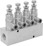 |
Multiple Regulators Shown Installed (Manifold Sold Separately) |
Mount these miniature regulators on a manifold (sold separately) to create a regulating manifold. Each regulator can be set to a different output pressure, so you can power multiple tools or machines with a single air supply. All are relieving regulators, so they exhaust when the downstream pressure exceeds the set pressure. Install them in your air line after filters.
Metric Male Inlet × Push to Connect Female Outlet
 |
Regulators | 4-Outlet Manifolds | 6-Outlet Manifolds | 10-Outlet Manifolds | ||||||||||||||||
|---|---|---|---|---|---|---|---|---|---|---|---|---|---|---|---|---|---|---|---|
Overall | |||||||||||||||||||
Inlet Thread Size | For Outlet Tube OD, mm | Max. Flow Rate @ Pressure | Max. Pressure, psi | Housing Material | Gauge Included | Wd. | Ht. | Max. Temp., ° F | Regulating Accuracy | Pressure Regulation, psi | Each | Each | Each | Each | |||||
| M5 × 0.8 mm | 4 | 2.8 scfm @ 100 psi | 115 | Polyester Plastic | No | 3/8" | 2" | 140 | ±4.4 psi | 14 to 101 | 8289N14 | 000000 | 8289N16 | 000000 | 8289N17 | 000000 | 8289N18 | 000000 | |
| M5 × 0.8 mm | 6 | 2.8 scfm @ 100 psi | 115 | Polyester Plastic | No | 3/8" | 2" | 140 | ±4.4 psi | 14 to 101 | 8289N15 | 00000 | 8289N16 | 00000 | 8289N17 | 00000 | 8289N18 | 00000 | |
Clean Room Pressure-Regulating Valves for Water, Air, and Inert Gas
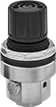 |
To maintain contaminant-free standards in clean room environments, these valves come cleaned and bagged to Fed. Std. Class 100 and ISO Class 5 clean room standards and have a 316 stainless steel body with a smooth finish to resist dust collection. They automatically reduce a high, variable inlet pressure to a lower, stable output pressure. Adjust the outlet pressure within the range. Valves are no-bleed style, so they keep process media contained within the valve.
Inlet | Outlet | |||||||||||||||
|---|---|---|---|---|---|---|---|---|---|---|---|---|---|---|---|---|
Thread Size | Location | Max. Pressure, psi | Thread Size | Location | Pressure Range, psi | Pressure Adjustment Method | Pressure Gauge Included | End-to-End Lg. | Panel Cutout Dia. | Clean Room Std. | For Use With | Temp. Range, ° F | Each | |||
Metric Female | ||||||||||||||||
316 Stainless Steel Body—Fluoroelastomer Diaphragm and 316 Stainless Steel Seal | ||||||||||||||||
| M5 × 0.8 mm | Side | 150 | M5 × 0.8 mm | Side | 1.4 to 28 | Knob | No | 1 3/16" | 1 1/4" | Fed. Std. Class 100, ISO Class 5 | Deionized Water, Air, Nitrogen, Oxygen | 41 to 140 | 4390T111 | 0000000 | ||
| M5 × 0.8 mm | Side | 150 | M5 × 0.8 mm | Side | 7 to 99 | Knob | No | 1 3/16" | 1 1/4" | Fed. Std. Class 100, ISO Class 5 | Deionized Water, Air, Nitrogen, Oxygen | 41 to 140 | 4390T112 | 000000 | ||
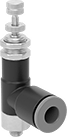
Elbow Air Flow Control Valves
Metric Male Inlet × Metric Female Outlet
 | 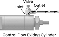 |
Meter Out |
Inlet | Outlet | Flow Rate @ 100 psi | ||||||||||||
|---|---|---|---|---|---|---|---|---|---|---|---|---|---|---|
Thread Size | Thread Pitch, mm | Thread Size | Thread Pitch, mm | Flow Coefficient (Cv) | Min. | Max., scfm | Max. Pressure, psi | Temp. Range, ° F | Flow Adjustment Mechanism | Flow Control Location (ISO Designation) | Each | |||
Zinc Alloy Body | ||||||||||||||
| M5 | 0.8 | M5 | 0.8 | 0.1 | Not Rated | 3.5 | 145 | 15 to 140 | Dial | Exiting Cylinder (Meter Out) | 6857K24 | 000000 | ||
Metric Male Inlet × Push-to-Connect Female Outlet
 | |
Meter Out |
Inlet | Flow Rate @ 100 psi, scfm | ||||||||||||
|---|---|---|---|---|---|---|---|---|---|---|---|---|---|
Thread Size | Thread Pitch, mm | For Outlet Tube OD, mm | Flow Coefficient (Cv) | Min. | Max. | Max. Pressure, psi | Temp. Range, ° F | Flow Adjustment Mechanism | Flow Control Location (ISO Designation) | Each | |||
Polybutylene Body | |||||||||||||
| M5 | 0.8 | 4 | 0.08 | 0 | 2.6 | 150 | 0 to 175 | Dial | Exiting Cylinder (Meter Out) | 62005K511 | 000000 | ||
| M5 | 0.8 | 6 | 0.08 | 0 | 2.6 | 150 | 0 to 175 | Dial | Exiting Cylinder (Meter Out) | 62005K512 | 00000 | ||
Elbow Air Flow Control Valves with Flow Indicator
Metric Male Inlet × Push-to-Connect Female Outlet
|  |
Meter Out |
Inlet | Flow Rate @ 73 psi, scfm | ||||||||||||
|---|---|---|---|---|---|---|---|---|---|---|---|---|---|
Thread Size | Thread Pitch, mm | For Outlet Tube OD, mm | Flow Coefficient (Cv) | Min. | Max. | Max. Pressure, psi | Temp. Range, ° F | Flow Adjustment Mechanism | Flow Control Location (ISO Designation) | Each | |||
Polybutylene Body with Flow Indicator | |||||||||||||
| M5 | 0.8 | 4 | 0.08 | 0 | 5.2 | 145 | 25 to 140 | Dial | Exiting Cylinder (Meter Out) | 2768N23 | 000000 | ||
| M5 | 0.8 | 6 | 0.08 | 0 | 5.2 | 145 | 25 to 140 | Dial | Exiting Cylinder (Meter Out) | 2768N24 | 00000 | ||
Elbow Corrosion-Resistant Air Flow Control Valves
Metric Male Inlet × Push-to-Connect Female Outlet
 | |
Meter Out |
Flow Rate @ 73 psi, scfm | ||||||||||||
|---|---|---|---|---|---|---|---|---|---|---|---|---|
Inlet Thread Size | For Outlet Tube OD, mm | Flow Coefficient (Cv) | Min. | Max. | Max. Pressure, psi | Temp. Range, ° F | Flow Adjustment Mechanism | Flow Control Location (ISO Designation) | Each | |||
Polybutylene Body with Pressure-Release Button | ||||||||||||
| M5 | 6 | 0.07 | 0 | 2.6 | 145 | 25 to 140 | Dial | Exiting Cylinder (Meter Out) | 9066K51 | 000000 | ||
Single-Control Two-Direction Air Flow Control Valves
Metric Female Inlet × Metric Female Outlet
 |  |  |
Meter Out | Meter In |
Inlet | Outlet | Flow Rate @ 100 psi | ||||||||||||
|---|---|---|---|---|---|---|---|---|---|---|---|---|---|---|
Thread Size | Thread Pitch, mm | Thread Size | Thread Pitch, mm | Flow Coefficient (Cv) | Min. | Max., scfm | Max. Pressure, psi | Temp. Range, ° F | Flow Adjustment Mechanism | Flow Control Location (ISO Designation) | Each | |||
Aluminum Body | ||||||||||||||
| M5 | 0.8 | M5 | 0.8 | 0.09 | Not Rated | 3.33 | 145 | -4 to 140 | Dial | Exiting Cylinder (Meter Out), Entering Cylinder (Meter In) | 8642K11 | 0000000 | ||
