


Filter by
System of Measurement
For Use With
Thread Type
Fitting Connection

Outlet Pressure
Inlet Connection
Outlet Thread Type
Maximum Inlet Pressure
Body Material
Minimum Pressure Regulation
Component
DFARS Specialty Metals
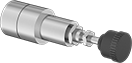
Panel-Mount Precision Compressed Air Regulators
Relieving Regulators
 |
Thread Size | Overall | |||||||||||||||
|---|---|---|---|---|---|---|---|---|---|---|---|---|---|---|---|---|
Inlet | Outlet | Max. Flow Rate @ Pressure | Max. Pressure, psi | Gauge Included | No. of Gauge Ports | For Panel Cutout Dia. | Wd. | Ht. | Housing Material | Max. Temp., ° F | Mounting Hardware Included | Choose Pressure Regulation, psi | Each | |||
UNF Female Inlet × UNF Female Outlet | ||||||||||||||||
±0.5% Regulating Accuracy | ||||||||||||||||
| 10-32 | 10-32 | 5 scfm @ 100 psi | 250 | No | 1 | 3/8" | 7/8" | 3 1/4" | Aluminum | 150 | Yes | 0 to 5, 0 to 15, 0 to 30, 0 to 60, 0 to 100 | 41795K2 | 000000 | ||
Miniature Panel-Mount Pressure-Regulating Valves for Water, Air, and Inert Gas
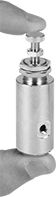 |
Our smallest pressure-regulating valves automatically reduce a high, variable inlet pressure to a lower, stable outlet pressure in tight spaces where other valves can't fit. Adjust the outlet pressure within the range. Valves have threads below the adjustment screw and comes with a panel-mount nut. Body is nickel-plated brass for good corrosion resistance.
Inlet | Outlet | |||||||||||||
|---|---|---|---|---|---|---|---|---|---|---|---|---|---|---|
Thread Size | Location | Max. Pressure, psi | Thread Size | Location | Pressure Range, psi | Pressure Adjustment Method | Port-to-Port Lg. | Panel Cutout Dia. | For Use With | Temp. Range, ° F | Each | |||
UNF Female | ||||||||||||||
Nickel-Plated Brass Body—Buna-N Seal | ||||||||||||||
| 10-32 | Bottom | 80 | 10-32 | Side | 5 to 80 | Screw | 3/8" | 1/2" | Water, Air, Inert Gas | 32 to 180 | 3834T51 | 000000 | ||
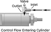
Inline Air Flow Control Valves
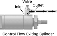
UNF Male Inlet × Barbed Male Outlet
 |  |  |
Meter Out | Meter In |
Flow Rate @ 100 psi, scfm | |||||||||||
|---|---|---|---|---|---|---|---|---|---|---|---|
Inlet Thread Size | Flow Coefficient (Cv) | Min. | Max. | Max. Pressure, psi | Temp. Range, ° F | Flow Adjustment Mechanism | Flow Control Location (ISO Designation) | Each | |||
Brass Body | |||||||||||
| 10-32 | 0.1 | 1 | 7 | 250 | -40 to 250 | Dial | Exiting Cylinder (Meter Out), Entering Cylinder (Meter In) | 6692K15 | 000000 | ||
UNF Male Inlet × UNF Female Outlet
 | | |
Meter Out | Meter In |
Flow Rate @ 100 psi, scfm | ||||||||||||
|---|---|---|---|---|---|---|---|---|---|---|---|---|
Inlet Thread Size | Outlet Thread Size | Flow Coefficient (Cv) | Min. | Max. | Max. Pressure, psi | Temp. Range, ° F | Flow Adjustment Mechanism | Flow Control Location (ISO Designation) | Each | |||
Brass Body | ||||||||||||
| 1/4"-28 | 1/4"-28 | 0.1 | 1 | 8 | 250 | -40 to 250 | Dial | Exiting Cylinder (Meter Out), Entering Cylinder (Meter In) | 6692K17 | 000000 | ||
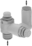
Elbow Air Flow Control Valves with Flow Indicator
UNF Male Inlet × Push-to-Connect Female Outlet
 |  |
Meter Out |
Flow Rate @ 73 psi, scfm | ||||||||||||
|---|---|---|---|---|---|---|---|---|---|---|---|---|
Inlet Thread Size | For Outlet Tube OD | Flow Coefficient (Cv) | Min. | Max. | Max. Pressure, psi | Temp. Range, ° F | Flow Adjustment Mechanism | Flow Control Location (ISO Designation) | Each | |||
Polybutylene Body with Flow Indicator | ||||||||||||
| 10-32 | 1/8" | 0.08 | 0 | 2.6 | 145 | 25 to 140 | Dial | Exiting Cylinder (Meter Out) | 2768N11 | 000000 | ||
| 10-32 | 5/32" | 0.08 | 0 | 2.6 | 145 | 25 to 140 | Dial | Exiting Cylinder (Meter Out) | 2768N12 | 00000 | ||
| 10-32 | 1/4" | 0.08 | 0 | 2.6 | 145 | 25 to 140 | Dial | Exiting Cylinder (Meter Out) | 2768N13 | 00000 | ||
Panel-Mount Back-Pressure-Regulating Valves for Air and Inert Gas
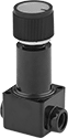 |
Threads below the adjustment knob and an included panel-mount nut allow you to add these valves to your instrument panel. Often used in systems running on air compressors, they're installed after pressure-sensitive equipment to obstruct flow and maintain a consistent operating pressure. If the system pressure exceeds the set pressure, they exhaust through the outlet. Adjust the set pressure within the range.
Inlet | Outlet | |||||||||||||
|---|---|---|---|---|---|---|---|---|---|---|---|---|---|---|
Thread Size | Location | Max. Pressure, psi | Thread Size | Location | Pressure Adjustment Method | End-to-End Lg. | Panel Cutout Dia. | For Use With | Temp. Range, ° F | Choose an Outlet Pressure, psi | Each | |||
UNF Female | ||||||||||||||
Polysulfone Body—Buna-N Diaphragm and Silicone Seal | ||||||||||||||
| 10-32 | Side | 100 | 10-32 | Side | Knob | 1 1/8" | 9/16" | Air, Inert Gas | 40 to 150 | 0.5 to 3.5, 0.5 to 10, 0.5 to 30, 0.5 to 60, 0.5 to 90 | 99045K12 | 000000 | ||
Corrosion-Resistant Single-Control Two-Direction Air Flow Control Valves
UNF Male Inlet × Push-to-Connect Female Outlet
|  |  |
Meter Out | Meter In |
Flow Rate @ 73 psi, scfm | ||||||||||||
|---|---|---|---|---|---|---|---|---|---|---|---|---|
Inlet Thread Size | For Outlet Tube OD | Flow Coefficient (Cv) | Min. | Max. | Max. Pressure, psi | Temp. Range, ° F | Flow Adjustment Mechanism | Flow Control Location (ISO Designation) | Each | |||
Polybutylene Body with Swiveling Outlet Connection | ||||||||||||
| 10-32 | 1/8" | 0.07 | 0 | 3 | 145 | 25 to 140 | Dial | Exiting Cylinder (Meter Out), Entering Cylinder (Meter In) | 2814N21 | 000000 | ||
Elbow Air Flow Control Valves
UNF Male Inlet × Push-to-Connect Female Outlet
 | |
Meter Out |
Flow Rate @ 100 psi, scfm | ||||||||||||
|---|---|---|---|---|---|---|---|---|---|---|---|---|
Inlet Thread Size | For Outlet Tube OD | Flow Coefficient (Cv) | Min. | Max. | Max. Pressure, psi | Temp. Range, ° F | Flow Adjustment Mechanism | Flow Control Location (ISO Designation) | Each | |||
Nylon Body | ||||||||||||
| 10-32 | 1/8" | 0.09 | — | — | 145 | 35 to 155 | Dial | Exiting Cylinder (Meter Out) | 45045K27 | 000000 | ||
| 10-32 | 5/32" | 0.09 | 0 | 2.7 | 145 | 35 to 155 | Dial | Exiting Cylinder (Meter Out) | 45045K29 | 00000 | ||
| 10-32 | 1/4" | 0.25 | 0 | 3.0 | 145 | 35 to 155 | Dial | Exiting Cylinder (Meter Out) | 45045K31 | 00000 | ||
Polybutylene Body | ||||||||||||
| 10-32 | 1/8" | 0.08 | 0 | 2.6 | 150 | 0 to 175 | Dial | Exiting Cylinder (Meter Out) | 62005K211 | 00000 | ||
| 10-32 | 5/32" | 0.08 | 0 | 2.6 | 150 | 0 to 175 | Dial | Exiting Cylinder (Meter Out) | 62005K212 | 00000 | ||
UNF Female Inlet × UNF Male Outlet
 | |
Meter In |
Flow Rate @ 73 psi, scfm | ||||||||||||
|---|---|---|---|---|---|---|---|---|---|---|---|---|
Inlet Thread Size | Outlet Thread Size | Flow Coefficient (Cv) | Min. | Max. | Max. Pressure, psi | Temp. Range, ° F | Flow Adjustment Mechanism | Flow Control Location (ISO Designation) | Each | |||
Zinc Alloy Body | ||||||||||||
| 10-32 | 10-32 | 0.02 | 0 | 4.2 | 145 | 32 to 140 | Dial | Entering Cylinder (Meter In) | 8346K14 | 000000 | ||
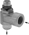
Elbow Corrosion-Resistant Air Flow Control Valves
UNF Male Inlet × Push-to-Connect Female Outlet
 | |
Meter Out |
Flow Rate @ 73 psi, scfm | ||||||||||||
|---|---|---|---|---|---|---|---|---|---|---|---|---|
Inlet Thread Size | For Outlet Tube OD | Flow Coefficient (Cv) | Min. | Max. | Max. Pressure, psi | Temp. Range, ° F | Flow Adjustment Mechanism | Flow Control Location (ISO Designation) | Each | |||
Polybutylene Body | ||||||||||||
| 10-32 | 1/8" | 0.1 | 0 | 4 | 145 | 32 to 140 | Dial | Exiting Cylinder (Meter Out) | 9066K34 | 000000 | ||
Polybutylene Body with Pressure-Release Button | ||||||||||||
| 10-32 | 5/32" | 0.07 | 0 | 2.6 | 145 | 25 to 140 | Dial | Exiting Cylinder (Meter Out) | 9066K41 | 00000 | ||
| 10-32 | 1/4" | 0.07 | 0 | 2.6 | 145 | 25 to 140 | Dial | Exiting Cylinder (Meter Out) | 9066K42 | 00000 | ||
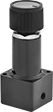
Precision-Adjust Air Flow Control Valves
UNF Male Inlet × Push-to-Connect Female Outlet
 | |
Meter Out |
Flow Rate @ 100 psi, scfm | ||||||||||||
|---|---|---|---|---|---|---|---|---|---|---|---|---|
Inlet Thread Size | For Outlet Tube OD | Flow Coefficient (Cv) | Min. | Max. | Max. Pressure, psi | Temp. Range, ° F | Flow Adjustment Mechanism | Flow Control Location (ISO Designation) | Each | |||
Nylon Body | ||||||||||||
| 10-32 | 1/8" | 0.09 | 0 | 2.5 | 145 | 35 to 155 | Dial | Exiting Cylinder (Meter Out) | 4076K29 | 000000 | ||
| 10-32 | 5/32" | 0.09 | 0 | 2.7 | 145 | 35 to 155 | Dial | Exiting Cylinder (Meter Out) | 4076K32 | 00000 | ||
| 10-32 | 1/4" | 0.25 | 0 | 3 | 145 | 35 to 155 | Dial | Exiting Cylinder (Meter Out) | 4076K21 | 00000 | ||
Plastic Panel-Mount Pressure-Regulating Valves for Air
 |
Regulate pressure in air systems from your instrument panel—these valves have threads below the adjustment knob and come with a panel-mount nut. All automatically reduce a high, variable inlet pressure to a lower, stable outlet pressure. Adjust the outlet pressure within the range. Body is polysulfone, which is lightweight and corrosion resistant.
Inlet | Outlet | |||||||||||||
|---|---|---|---|---|---|---|---|---|---|---|---|---|---|---|
Thread Size | Location | Max. Pressure, psi | Thread Size | Location | Pressure Adjustment Method | End-to-End Lg. | Panel Cutout Dia. | For Use With | Temp. Range, ° F | Choose an Outlet Pressure, psi | Each | |||
UNF Female | ||||||||||||||
Polysulfone Body—Buna-N/EPDM Diaphragm and Polyurethane Rubber Seal | ||||||||||||||
| 10-32 | Side | 150 | 10-32 | Side | Knob | 1 1/8" | 9/16" | Air | 40 to 150 | 0.5 to 3.5, 0.5 to 30, 0.5 to 60, 0.5 to 90 | 43275K36 | 000000 | ||
