


Filter by

Wire Connection
Base Cover Style
Electrical Connector Component

System of Measurement
Wire Connection Method
Housing Finish
Electrical Connection
Maximum Temperature
DFARS Specialty Metals
Export Control Classification Number (ECCN)
Certification
Latching Connectors
Side Conduit Connection—1 Latching Lever
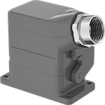 |  |
With Attached Cover |
Latching connectors with one latching lever quickly disconnect with one hand.
IP65 Enclosure Rating—IP65 rated connectors protect against dust and rinsing.
NEMA 4X Enclosure Rating—NEMA 4X rated connectors protect against washdowns.
NEMA 12 Enclosure Rating—NEMA 12 rated connectors resist oil/coolant dripping.
Conduit | |||||||||||||||||||
|---|---|---|---|---|---|---|---|---|---|---|---|---|---|---|---|---|---|---|---|
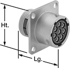
No. of Poles | Voltage | Current, amp | Trade Size | Thread Type | Connection Gender | Wire Connection | For Wire Ga. | Lg. | Wd. | Ht. | Base Cover Style | Max. Temp., ° F | Certification | Enclosure Rating | Color | Each | |||
Powder-Coated Aluminum Housing | |||||||||||||||||||
| 48 | 600V AC/600V DC | 16 | 1 1/4 | NPT | Female | Screw Terminal, Wire Inlet | 18, 17, 16, 15, 14 | 6.5" | 3.8" | 5.4" | Attached | 255 | UL Recognized Component | IP65, NEMA 4X, NEMA 12 | Gray | 3240K19 | 0000000 | ||
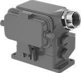
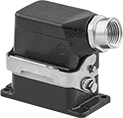
Top Conduit Connection—1 Latching Lever
 |  |
With Attached Cover |
Latching connectors with one latching lever quickly disconnect with one hand.
IP65 Enclosure Rating—IP65 rated connectors protect against dust and rinsing.
NEMA 4X Enclosure Rating—NEMA 4X rated connectors protect against washdowns.
NEMA 12 Enclosure Rating—NEMA 12 rated connectors resist oil/coolant dripping.
Conduit | |||||||||||||||||||
|---|---|---|---|---|---|---|---|---|---|---|---|---|---|---|---|---|---|---|---|
No. of Poles | Voltage | Current, amp | Trade Size | Thread Type | Connection Gender | Wire Connection | For Wire Ga. | Lg. | Wd. | Ht. | Base Cover Style | Max. Temp., ° F | Certification | Enclosure Rating | Color | Each | |||
Powder-Coated Aluminum Housing | |||||||||||||||||||
| 48 | 600V AC/600V DC | 16 | 1 1/4 | NPT | Female | Screw Terminal, Wire Inlet | 18, 17, 16, 15, 14 | 6.5" | 3.8" | 5.4" | Attached | 255 | UL Recognized Component | IP65, NEMA 4X, NEMA 12 | Gray | 3240K25 | 0000000 | ||
Mil. Spec. Compatible Connectors
Crimp-On Plugs—Internal Housing Lock
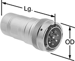 |  |
48 Poles (Clockwise) |
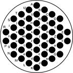
Crimp-On Sockets—Internal Housing Lock
 |  |
48 Poles (Counterclockwise) |
Mil. Spec. Sockets | Crimpers | ||||||||||||||
|---|---|---|---|---|---|---|---|---|---|---|---|---|---|---|---|
No. of Poles | Pole Layout | Voltage | Current, amp | For Wire Ga. | For Cable OD | OD | Lg. | Housing Material | Temp. Range, ° F | Connector Shell Size | Each | Each | |||
| 48 | Counterclockwise | 500V AC/500V DC | 3 | 26, 25, 24, 23, 22, 21, 20, 19, 18 | 0.81" to 0.88" | 1.8" | 3.5" | Nickel-Plated Zinc Alloy | -40 to 220 | 24 | 6168T117 | 0000000 | 6168T3 | 000000000 | |
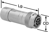
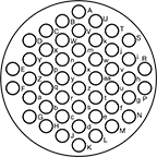
Female Panel-Mount Crimp-On Receptacles—External Housing Lock
 | |
48 Poles (Counterclockwise) |
Mil. Spec. Receptacles | Crimpers | |||||||||||||||
|---|---|---|---|---|---|---|---|---|---|---|---|---|---|---|---|---|
No. of Poles | Pole Layout | Voltage | Current, amp | For Wire Ga. | Lg. | Wd. | Ht. | Housing Material | For Panel Cutout Dia. | Temp. Range, ° F | Connector Shell Size | Each | Each | |||
| 48 | Counterclockwise | 500V AC/500V DC | 3 | 26, 25, 24, 23, 22, 21, 20, 19, 18 | 1.5" | 1.7" | 1.7" | Nickel-Plated Zinc Alloy | 1.4" | -40 to 220 | 24 | 6168T108 | 000000 | 6168T3 | 000000000 | |
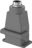
Build-Your-Own Latching Connectors
 |
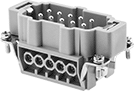 |
Male |
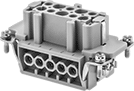 |
Female |
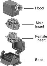
Configure a connector for your application—combine male and female inserts with a base and a hood. Select components based on the number of poles needed. To protect connections while maintaining access, the base and hood latch together securely, yet can be quickly detached for equipment repair or replacement. Once assembled, these connectors are rated NEMA 4X, 12, and IP65 for protection against corrosion, washdowns, dirt, oil/coolant dripping, and water projected from a nozzle.
Inserts | Hoods with Side Conduit Connection | Hoods with Top Conduit Connection | Bases | |||||||||||||||
|---|---|---|---|---|---|---|---|---|---|---|---|---|---|---|---|---|---|---|
Male | Female | |||||||||||||||||
No. of Poles | Voltage | Current, amp | For Wire Ga. | Latching Connector Insert Type | Each | Each | Conduit Trade Size | Each | Conduit Trade Size | Each | Each | |||||||
Spring-Clamp-Terminal Wire Inlet Connection | ||||||||||||||||||
| 48 | 600V AC/600V DC | 16 | 26, 25, 24, 23, 22, 21, 20, 19, 18, 17, 16, 15, 14 | Power, Signal | 8037K36 | 000000 | 8037K37 | 000000 | 1 | 8037K89 | 000000 | 1 | 8037K88 | 000000 | 8037K71 | 000000 | ||
Screw-Terminal Wire Inlet Connection | ||||||||||||||||||
| 48 | 600V AC/600V DC | 16 | 18, 17, 16, 15, 14 | Power, Signal | 8037K96 | 00000 | 8037K97 | 00000 | 1 | 8037K89 | 00000 | 1 | 8037K88 | 00000 | 8037K71 | 00000 | ||
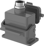
Harsh Environment Latching Connectors
Side Conduit Connection—1 Latching Lever
 |
Conduit | |||||||||||||||||||
|---|---|---|---|---|---|---|---|---|---|---|---|---|---|---|---|---|---|---|---|
No. of Poles | Voltage | Current, amp | Trade Size | Thread Type | Connection Gender | Wire Connection | For Wire Ga. | Lg. | Wd. | Ht. | Base Cover Style | Max. Temp., ° F | Certification | Enclosure Rating | Color | Each | |||
Powder-Coated Aluminum Housing | |||||||||||||||||||
| 48 | 600V AC/600V DC | 16 | 1 1/4 | NPT | Female | Screw Terminal, Wire Inlet | 18, 17, 16, 15, 14 | 6.5" | 3.8" | 5.4" | Attached | 255 | UL Recognized Component | IP65, NEMA 4X, NEMA 12 | Black | 3240K45 | 0000000 | ||
