


Filter by
Product Family
Weight Capacity
Brake Type


Overall Height
Mobility

Weight Capacity @ 4 ft.
U.S.–Mexico–Canada Agreement (USMCA) Qualifying
Color
DFARS Specialty Metals
Export Control Classification Number (ECCN)
Height
Weight Capacity @ 6 ft.
Boom Adjustability
Specifications Met
Clearance Adjustment Increments
Crane Beam Type
Performance
Adjustable Gantry Cranes for Rough Surfaces
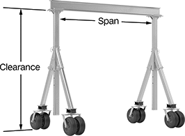 |
Roll these cranes over grass, gravel, and even mud to lift heavy loads. Equipped with air-filled wheels, they absorb shock better than any of our other gantry cranes, moving smoothly across rough and uneven surfaces. The wheels are butyl rubber for traction even when it’s slick. Made of aluminum, these cranes are strong but lightweight. They resist corroding in the rain and other wet conditions. Lock the wheels to secure these cranes in place. They are not meant to be moved while under load.
Suitable for a wide range of spaces, these cranes also have a beam you can adjust depending on how much vertical clearance you need. Raise the beam to lift large loads or lower it if overhead space is tight. Attach a manual or motorized trolley to the beam to move a load along the length of the span.
Warning: Never use to lift people or items over people.
Overall | Beam | |||||||||||||||
|---|---|---|---|---|---|---|---|---|---|---|---|---|---|---|---|---|
Wt. Cap. | Clearance, ft. | Clearance Adjustment Increments | Lg., ft. | Wd. | Ht. | Wd. | Ht. | Type | Wheel Configuration | Brake Type | Wheel Material | Specs. Met | Each | |||
Aluminum | ||||||||||||||||
104" Span | ||||||||||||||||
| 3/4 ton, 1,500 lb. | 8 to 10 | 6" | 10 | 53" | 104" to 134" | 3 5/16" | 6" | Open | Four Swivel Casters | Wheel Brake | Butyl | ASME B30.17, OSHA Compliant 29 CFR 1910.179 | 7310N105 | 000000000 | ||
Forklift Booms
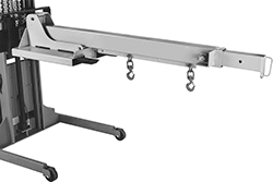 |
Shown Installed on Forklift |
Slide these booms onto forklift forks to handle long, cumbersome loads. They secure to the forklift carriage with the included safety chains. These booms are labeled with capacity for each hook position. First hook position is measured from the fork pocket end.
Note: Capacities are approximate and depend on the type and load capabilities of the forklift used. Check with the manufacturer of your forklift for load capabilities before using.
Warning: Never use to lift people or items over people.
Caldwell Forklift Booms
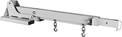 | 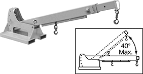 |
Style F | Style H |
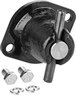 | 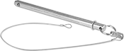 |
Replacement Pin Housing Rebuild Kits | Replacement Pull Pins |
Forklift Booms | Replacement Pin Housing Rebuild Kits | Replacement Pull Pins | |||||||||||||||||||||||||||
|---|---|---|---|---|---|---|---|---|---|---|---|---|---|---|---|---|---|---|---|---|---|---|---|---|---|---|---|---|---|
Wt. Cap., lb. | For Max. Fork | Hook | |||||||||||||||||||||||||||
Style | @ 3 ft. | @ 4 ft. | @ 5 ft. | @ 6 ft. | @ 7 ft. | @ 8 ft. | @ 9 ft. | @ 10 ft. | @ 11 ft. | @ 12 ft. | Fork Pocket Spacing Ctr.-to-Ctr. | For Min. Fork Lg. | Wd. | Ht. | Material | Type | Movement | Opening Wd. | First Hook Position, ft. | Lg., ft. | Country of Origin | Each | Each | Each | |||||
Horizontally Telescoping | |||||||||||||||||||||||||||||
| F | 4,000 | 4,000 | 4,000 | 4,000 | 3,200 | 2,600 | 2,200 | 1,900 | 1,600 | 1,500 | 15" | 30" | 7 1/2" | 2 1/2" | Painted Steel | Latching | Swivel | 1 1/16" | 3 | 7 to 12 | United States | 3638T22 | 000000000 | 3638T42 | 0000000 | ——— | 0 | ||
Horizontally Telescoping, Vertically Adjustable (40° Maximum Lifting Angle) | |||||||||||||||||||||||||||||
| H | 4,000 | 4,000 | 4,000 | 4,000 | 3,200 | 2,600 | 2,200 | 1,900 | 1,600 | 1,500 | 15" | 30" | 7 1/2" | 2 1/2" | Painted Steel | Latching | Swivel | 1 1/16" | 3 | 7 to 12 | United States | 3638T25 | 00000000 | 3638T42 | 000000 | 3638T43 | 0000000 | ||
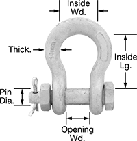 |
A bolt fastened with a nut and cotter pin makes these shackles more secure than screw-pin shackles. Also known as anchor and bow shackles, the wide body provides room to attach multiple connectors.
Note: Capacities listed are for vertical lifting only. As the lift angle changes from vertical, the amount of weight the shackle can lift is significantly reduced.
Galvanized Steel—Galvanized steel shackles have a thick coating for corrosion resistance.
Wt. Cap., lb. | Thk. | Pin Dia. | Opening Wd. | Inside Lg. | Inside Wd. | Specs. Met | Mil. Spec. | Each | |||
|---|---|---|---|---|---|---|---|---|---|---|---|
Galvanized Steel | |||||||||||
| 7,100 | 5/8" | 25/32" | 1 1/16" | 2 13/32" | 1 23/32" | ASME B30.26 | Fed. Spec. RR-C-271 | 3555T52 | 000000 | ||
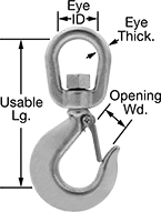 |
Rotating for easy positioning before a load is applied, these have a latch to ensure that rope, chain, and fittings won't separate from the hook when the load slackens. The hook opening accommodates large anchor points and allows chain to move freely through the closed hook.
Note: Capacities are for vertical lifting only.
Hook | Eye | ||||||||
|---|---|---|---|---|---|---|---|---|---|
Wt. Cap., lb. | Opening Wd. | Usable Lg. | ID | Thk. | Specs. Met | For Use With | Each | ||
| 4,400 | 1 1/16" | 6 1/8" | 1 3/4" | 5/8" | ASME B30.10 | Chain, Wire Rope | 3525T613 | 0000000 | |
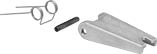 |
Includes | Each | ||
|---|---|---|---|
| Latch, Spring, Nut and Bolt | 35315T43 | 000000 |
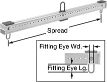
Steel Lifting Beams
Beams with Brackets
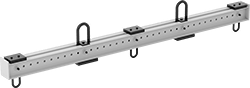 |  |
Shown with One Additional Upper and One Additional Lower Bracket |
