


Filter by
Number of Solenoids
Air Directional Control Valve Flow Pattern
Actuation Type


For Use With
Maximum Pressure
Valve Function
Maximum Flow Rate @ Pressure
Export Control Classification Number (ECCN)
U.S.–Mexico–Canada Agreement (USMCA) Qualifying
DFARS Specialty Metals
Inlet Connection


About Directional Control Valves
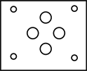
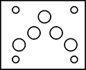
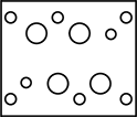
Choose the right valve for your application by matching the actions you'll power to our flow diagrams.
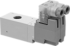
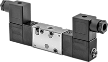
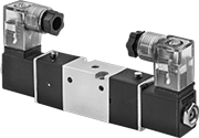
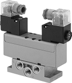
Two-Speed Two-Action Electrically Operated Air Directional Control Valves
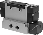 | 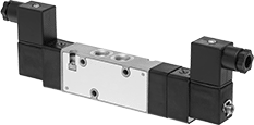 |
Style E | Style F |
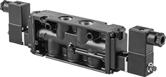 | 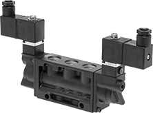 |
Style G | Style H |
 |  |
Style J | Style K |
Threaded Female Inlet × Threaded Female Outlet—Threaded Exhaust
| |
Style E | Style F |
| |
Style G | Style H |
| |
Style J |
Valves | Replacement Solenoid Valve Plugs | ||||||||||||||||||
|---|---|---|---|---|---|---|---|---|---|---|---|---|---|---|---|---|---|---|---|
Overall | |||||||||||||||||||
Style | No. of Flow Ports | Inlet Size | Outlet Size | Max. Flow Rate @ 100 psi, scfm | Flow Coefficient (Cv) | Pressure Range, psi | Vacuum Rating | Lg. | Wd. | Ht. | Mount Type | For Manifold Style | Choose a Voltage | Each | Each | ||||
Double Solenoid—Solenoid Return | |||||||||||||||||||
| E | 5 | 3/4 NPTF | 3/4 NPTF | 287 | 9 | 15 to 145 | Not Rated | 10 1/2" | 4 1/4" | 6 1/2" | Screw In | — | 24V DC, 120V AC | 4701T8 | 0000000 | ——— | 0 | ||
| F | 5 | 1/8 NPT | 1/8 NPT | 43.1 | 0.75 | 29 to 145 | Not Rated | 6 7/8" | 7/8" | 2 1/2" | Manifold, Screw In | 1 | 12V DC, 24V DC, 120V AC | 6124K515 | 000000 | 6124K301 | 00000 | ||
| F | 5 | 1/8 NPTF | 1/8 NPTF | 56 | 1 | 15 to 150 | 28 in. Hg | 8 1/4" | 7/8" | 2 3/4" | Manifold, Screw In | 2 | 24V DC, 120V AC | 6425K12 | 000000 | ——— | 0 | ||
| F | 5 | 1/4 NPT | 1/4 NPT | 43.1 | 1.3 | 29 to 145 | Not Rated | 7 7/8" | 1" | 2 5/8" | Manifold, Screw In | 3 | 12V DC, 24V DC, 120V AC | 6124K516 | 000000 | 6124K301 | 0000 | ||
| F | 5 | 1/4 NPTF | 1/4 NPTF | 56 | 1 | 15 to 150 | 28 in. Hg | 8 1/4" | 7/8" | 2 3/4" | Manifold, Screw In | 2 | 24V DC, 120V AC | 6425K14 | 000000 | ——— | 0 | ||
| F | 5 | 1/4 NPTF | 1/4 NPTF | 95.2 | 1.7 | 15 to 150 | 28 in. Hg | 8 7/8" | 1" | 3" | Manifold, Screw In | 4 | 24V DC, 120V AC | 6425K22 | 000000 | ——— | 0 | ||
| F | 5 | 3/8 NPTF | 3/8 NPTF | 95.2 | 1.7 | 15 to 150 | 28 in. Hg | 8 7/8" | 1" | 3" | Manifold, Screw In | 4 | 24V DC, 120V AC | 6425K24 | 000000 | ——— | 0 | ||
| G | 5 | 1/2 NPTF | 1/2 NPTF | 165.9 | 5 | 20 to 150 | Not Rated | 12 3/8" | 1 1/2" | 2 3/4" | Screw In | — | 24V DC, 120V AC | 6124K63 | 000000 | 6124K301 | 0000 | ||
| H | 5 | 3/8 NPTF | 3/8 NPTF | 53.1 | 1.6 | 35 to 150 | Not Rated | 9 1/4" | 1 1/4" | 5 1/4" | Screw In | — | 24V DC, 120V AC | 6124K62 | 000000 | ——— | 0 | ||
| J | 5 | 1/4 NPT | 1/4 NPT | 56 | 1 | 40 to 120 | Not Rated | 5 7/8" | 1 7/8" | 3 3/8" | Screw In | — | 12V DC, 24V DC, 120V AC, 240V AC | 6196K24 | 000000 | ——— | 0 | ||
 |
No. of | Overall | |||||||||||||
|---|---|---|---|---|---|---|---|---|---|---|---|---|---|---|
Stations | Flow Ports | Inlet Ports | Exhaust Ports | Inlet Size | Exhaust Connection | Wd. | Ht. | Mounting Hole Dia. | For DIN Rail Size, mm | Mounting Fasteners Included | Each | |||
Manifold Style 1 | ||||||||||||||
| 2 | 6 | 2 | 4 | 1/4 NPT | Threaded | 1 7/8" | 1 1/4" | 0.19" | 35 | Yes | 6124K341 | 000000 | ||
Manifold Style 3 | ||||||||||||||
| 2 | 6 | 2 | 4 | 3/8 NPT | Threaded | 2 1/8" | 1 1/4" | 0.19" | 35 | Yes | 6124K345 | 000000 | ||
| 3 | 6 | 2 | 4 | 3/8 NPT | Threaded | 3 1/8" | 1 1/4" | 0.19" | 35 | Yes | 6124K346 | 000000 | ||
For Manifold Style | Each | ||
|---|---|---|---|
| 1, 3 | 6124K344 | 000000 |
Push-to-Connect Female Inlet × Push-to-Connect Female Outlet—Push-to-Connect Exhaust
|
Style K |
Solenoid Return—Valves with solenoid return actuation go back to their original position when voltage is moved from the first solenoid to the second solenoid.
Flow Coefficient (Cv)—Flow coefficient (Cv) is a measurement that indicates how much airflow can pass through a valve. When selecting between valves with the same port size, choose the valve with the higher flow coefficient to ensure it provides enough airflow to operate your system.
Overall | ||||||||||||||||
|---|---|---|---|---|---|---|---|---|---|---|---|---|---|---|---|---|
Style | No. of Flow Ports | For Inlet Tube OD, mm | For Outlet Tube OD, mm | Max. Flow Rate @ 100 psi, scfm | Flow Coefficient (Cv) | Pressure Range, psi | Vacuum Rating, in. Hg | Lg. | Wd. | Ht. | Mount Type | Voltage, V DC | Each | |||
Double Solenoid—Solenoid Return | ||||||||||||||||
| K | 5 | 6 | 6 | 17.5 | 0.31 | 29 to 101 | 29.52 | 3 1/4" | 7/16" | 2 1/8" | Screw In | 24 | 4658A32 | 0000000 | ||
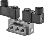
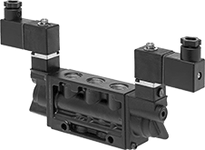
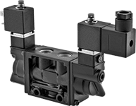
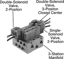
Modular Air Directional Control Valves with Air and Electrical Manifolds
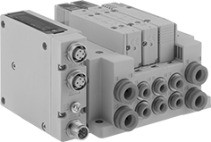 |
Complete System Shown with M12 Electrical Connection |
Mix and match valve styles on one manifold to meet your control needs. Mount multiple valves to a manifold to reduce piping requirements and create multiple actions from a single pressure input. Add or remove valves as your needs change.
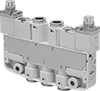
3-Way Valves
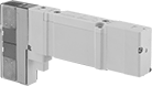 |
3-way valves create one action, such as extending a cylinder. They have four flow positions, which allows the valve to operate as two independent valves from a single station on the manifold.
Fail-Closed Valve—Fail-closed valves block airflow until actuated.
Air Return—Valves with air return actuation go back to their starting position when the air supply is moved from the first air pilot to the second air pilot.
Flow Coefficient (Cv)—Flow coefficient (Cv) indicates how much airflow can pass through a valve.
Overall | |||||||||||||||||
|---|---|---|---|---|---|---|---|---|---|---|---|---|---|---|---|---|---|
No. of Valves | Return Actuation | No. of Flow Ports | Max. Flow Rate @ 100 psi, scfm | Flow Coefficient (Cv) | Pressure Range, psi | Vacuum Rating | Voltage, V DC | Lg. | Wd. | Ht. | Mount Type | Body Material | Mounting Fasteners Included | Each | |||
3/2 Flow Pattern—Fail-Closed Valve | |||||||||||||||||
| 2 | Air | 3 | 148.41 | 1 | 22 to 102 | Not Rated | 24 | 4 1/16" | 11/16" | 2 3/16" | Manifold | Aluminum | Yes | 2866N26 | 000000 | ||
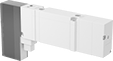
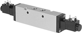
4-Way Valves
 |
Overall | |||||||||||||||||
|---|---|---|---|---|---|---|---|---|---|---|---|---|---|---|---|---|---|
No. of Valves | Return Actuation | No. of Flow Ports | Max. Flow Rate @ 100 psi, scfm | Flow Coefficient (Cv) | Pressure Range, psi | Vacuum Rating | Voltage, V DC | Lg. | Wd. | Ht. | Mount Type | Body Material | Mounting Fasteners Included | Each | |||
5/2 Flow Pattern | |||||||||||||||||
| 1 | Solenoid | 5 | 166.97 | 1 | 15 to 102 | Not Rated | 24 | 4 1/16" | 11/16" | 2 3/16" | Manifold | Aluminum | Yes | 2866N25 | 000000 | ||
5/3 (Closed Center) Flow Pattern | |||||||||||||||||
| 1 | Solenoid | 5 | 167 | 1 | 29 to 102 | Not Rated | 24 | 4 5/8" | 3/4" | 2 7/8" | Manifold | Aluminum | Yes | 2866N27 | 00000 | ||
5/3 (Exhaust Center) Flow Pattern | |||||||||||||||||
| 1 | Solenoid | 5 | 167 | 1 | 29 to 102 | Not Rated | 24 | 4 5/8" | 3/4" | 2 7/8" | Manifold | Aluminum | Yes | 2866N28 | 00000 | ||
5/3 (Pressure Center) Flow Pattern | |||||||||||||||||
| 1 | Solenoid | 5 | 167 | 1 | 29 to 102 | Not Rated | 24 | 4 5/8" | 3/4" | 2 7/8" | Manifold | Aluminum | Yes | 2866N29 | 00000 | ||
Two-Speed Two-Action Electrically Operated Air Directional Control Valves with Full Shut-Off
 |  |  |
Style A | Style B | Style C |
Threaded Female Inlet × Threaded Female Outlet—Threaded Exhaust
|
Style A |
|
Style B |
Solenoid Return—Valves with solenoid return actuation go back to their original position when voltage is moved from the first solenoid to the second solenoid.
NPTF Inlet Thread—NPTF (Dryseal) threads are compatible with NPT threads.
Manifold Mount—Manifold-mount valves plug into a manifold (sold separately) to create multiple actions from a single pressure input. Manifolds with multiple exhaust ports have one set of inlet and exhaust ports on each side, so they can be strung together in a series. When using a single manifold, cover the ports on the side you are not using with plugs (sold separately).
Flow Coefficient (Cv)—Flow coefficient (Cv) is a measurement that indicates how much airflow can pass through a valve. When selecting between valves with the same port size, choose the valve with the higher flow coefficient to ensure it provides enough airflow to operate your system.
Valves | Replacement Solenoid Valve Plugs | ||||||||||||||||||
|---|---|---|---|---|---|---|---|---|---|---|---|---|---|---|---|---|---|---|---|
Overall | |||||||||||||||||||
Style | No. of Flow Ports | Inlet Size | Outlet Size | Max. Flow Rate @ 100 psi, scfm | Flow Coefficient (Cv) | Pressure Range, psi | Vacuum Rating | Lg. | Wd. | Ht. | Mount Type | For Manifold Style | Choose a Voltage | Each | Each | ||||
Double Solenoid—Solenoid Return | |||||||||||||||||||
| A | 5 | 1/8 NPT | 1/8 NPT | 28 | 0.5 | 44 to 145 | Not Rated | 7 1/2" | 7/8" | 1 3/8" | Manifold, Screw In | 1 | 12V DC, 24V DC, 120V AC | 6124K2 | 0000000 | 6124K301 | 00000 | ||
| A | 5 | 1/8 NPTF | 1/8 NPTF | 56 | 1 | 15 to 150 | 28 in. Hg | 8 5/8" | 7/8" | 2 3/4" | Manifold, Screw In | 2 | 24V DC, 120V AC | 6425K17 | 000000 | ——— | 0 | ||
| A | 5 | 1/4 NPT | 1/4 NPT | 53 | 0.95 | 44 to 145 | Not Rated | 8 1/2" | 1" | 1 5/8" | Manifold, Screw In | 3 | 12V DC, 24V DC, 120V AC | 6124K3 | 000000 | 6124K301 | 0000 | ||
| A | 5 | 1/4 NPTF | 1/4 NPTF | 56 | 1 | 15 to 150 | 28 in. Hg | 8 5/8" | 7/8" | 2 3/4" | Manifold, Screw In | 2 | 24V DC, 120V AC | 6425K18 | 000000 | ——— | 0 | ||
| A | 5 | 1/4 NPTF | 1/4 NPTF | 95.2 | 1.7 | 15 to 150 | 28 in. Hg | 9 3/8" | 1" | 3" | Manifold, Screw In | 4 | 24V DC, 120V AC | 6425K27 | 000000 | ——— | 0 | ||
| A | 5 | 3/8 NPTF | 3/8 NPTF | 95.2 | 1.7 | 15 to 150 | 28 in. Hg | 9 3/8" | 1" | 3" | Manifold, Screw In | 4 | 24V DC, 120V AC | 6425K28 | 000000 | ——— | 0 | ||
| B | 5 | 3/8 NPT | 3/8 NPT | 93 | 1.67 | 45 to 150 | Not Rated | 9 3/8" | 1 1/4" | 4 3/4" | Screw In | — | 24V DC, 120V AC | 6124K4 | 000000 | ——— | 0 | ||
|
No. of | Overall | |||||||||||||
|---|---|---|---|---|---|---|---|---|---|---|---|---|---|---|
Stations | Flow Ports | Inlet Ports | Exhaust Ports | Inlet Size | Exhaust Connection | Wd. | Ht. | Mounting Hole Dia. | For DIN Rail Size, mm | Mounting Fasteners Included | Each | |||
Manifold Style 1 | ||||||||||||||
| 2 | 6 | 2 | 4 | 1/4 NPT | Threaded | 1 7/8" | 1 1/4" | 0.19" | 35 | Yes | 6124K341 | 000000 | ||
| 3 | 6 | 2 | 4 | 1/4 NPT | Threaded | 2 3/4" | 1 1/4" | 0.19" | 35 | Yes | 6124K342 | 000000 | ||
Manifold Style 3 | ||||||||||||||
| 2 | 6 | 2 | 4 | 3/8 NPT | Threaded | 2 1/8" | 1 1/4" | 0.19" | 35 | Yes | 6124K345 | 000000 | ||
| 3 | 6 | 2 | 4 | 3/8 NPT | Threaded | 3 1/8" | 1 1/4" | 0.19" | 35 | Yes | 6124K346 | 000000 | ||
For Manifold Style | Each | ||
|---|---|---|---|
| 1, 3 | 6124K344 | 000000 |
Push-to-Connect Female Inlet × Push-to-Connect Female Outlet—Push-to-Connect Exhaust
|
Style C |
Spring Return—Valves with spring return actuation go back to their original position when voltage is removed.
Flow Coefficient (Cv)—Flow coefficient (Cv) is a measurement that indicates how much airflow can pass through a valve. When selecting between valves with the same port size, choose the valve with the higher flow coefficient to ensure it provides enough airflow to operate your system.
Overall | ||||||||||||||||
|---|---|---|---|---|---|---|---|---|---|---|---|---|---|---|---|---|
Style | No. of Flow Ports | For Inlet Tube OD, mm | For Outlet Tube OD, mm | Max. Flow Rate @ 100 psi, scfm | Flow Coefficient (Cv) | Pressure Range, psi | Vacuum Rating, in. Hg | Lg. | Wd. | Ht. | Mount Type | Voltage, V DC | Each | |||
Double Solenoid—Spring Return | ||||||||||||||||
| C | 5 | 6 | 6 | 17.5 | 0.31 | 44 to 101 | 29.52 | 3 1/4" | 7/16" | 2 1/8" | Screw In | 24 | 4658A33 | 0000000 | ||
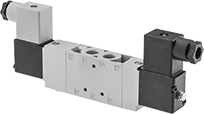
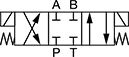
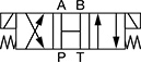
Two-Speed Two-Action Electrically Operated Air Directional Control Valves with Exhausting Shut-Off
 |
NPT Inlet Thread NPT Outlet Thread |
 |
NPTF Inlet Thread NPTF Outlet Thread |
In the off position, these valves exhaust all air pressure, allowing the equipment to return to the neutral position. Often used to extend and then retract a cylinder at different speeds, they create two actions and have two exhaust ports, which allows you to control the speed of each action by attaching a flow control valve to each exhaust port. Also known as 5/3 exhaust-center valves, they actuate when voltage is applied to the electrical connection. They direct airflow from the inlet to your equipment and exhaust return airflow to create motion. Return actuation is electric (solenoid), so they go back to their original position when voltage moves from the first solenoid to the second solenoid.
NPT Inlet Thread—Solenoid connectors are not included for NPT × NPT valves.
NPTF Inlet Thread—NPTF (Dryseal) threads are compatible with NPT threads.
Manifold Mount—Manifold-mount valves plug into a manifold (sold separately) to create multiple actions from a single pressure input. Manifolds with multiple exhaust ports have one set of inlet and exhaust ports on each side, so they can be strung together in a series. When using a single manifold, cover the ports on the side you are not using with plugs (sold separately).
Flow Coefficient (Cv)—Flow coefficient (Cv) is a measurement that indicates how much airflow can pass through a valve. When selecting between valves with the same port size, choose the valve with the higher flow coefficient to ensure it provides enough airflow to operate your system.
Overall | ||||||||||||||||||||
|---|---|---|---|---|---|---|---|---|---|---|---|---|---|---|---|---|---|---|---|---|
No. of Flow Ports | Inlet Size | Outlet Size | Exhaust Connection | Max. Flow Rate @ 100 psi, scfm | Flow Coefficient (Cv) | Pressure Range, psi | Vacuum Rating | Specs. Met | Lg. | Wd. | Ht. | Mount Type | For Manifold Style | Mounting Fasteners Included | Mounting Hole Dia. | Choose a Voltage | Each | |||
Threaded Female Inlet x Threaded Female Outlet | ||||||||||||||||||||
Double Solenoid—Solenoid Return | ||||||||||||||||||||
| 5 | 1/8 NPT | 1/8 NPT | Threaded | 19 | 0.6 | 43 to 145 | Not Rated | EN 175301-803 | 8 3/4" | 7/8" | 2 5/8" | Screw In | — | Yes | 0.16" | 24V DC | 2842N11 | 0000000 | ||
| 5 | 1/8 NPT | 1/8 NPT | Threaded | 19 | 0.6 | 43 to 145 | Not Rated | EN 175301-803 | 8 3/4" | 7/8" | 2 5/8" | Screw In | — | Yes | 0.16" | 120V AC | 2842N12 | 000000 | ||
| 5 | 1/8 NPTF | 1/8 NPTF | Threaded | 56 | 1 | 15 to 150 | 28 in. Hg | — | 8 5/8" | 7/8" | 2 3/4" | Manifold, Screw In | 2 | No | 0.13" | 24V DC, 120V AC | 6425K15 | 000000 | ||
| 5 | 1/4 NPT | 1/4 NPT | Threaded | 48 | 1.5 | 43 to 145 | Not Rated | EN 175301-803 | 9 1/4" | 7/8" | 2 5/8" | Screw In | — | Yes | 0.17" | 24V DC | 2842N13 | 000000 | ||
| 5 | 1/4 NPT | 1/4 NPT | Threaded | 48 | 1.5 | 43 to 145 | Not Rated | EN 175301-803 | 9 1/4" | 7/8" | 2 5/8" | Screw In | — | Yes | 0.17" | 120V AC | 2842N14 | 000000 | ||
| 5 | 1/4 NPTF | 1/4 NPTF | Threaded | 56 | 1 | 15 to 150 | 28 in. Hg | — | 8 5/8" | 7/8" | 2 3/4" | Manifold, Screw In | 2 | No | 0.13" | 24V DC, 120V AC | 6425K16 | 000000 | ||
| 5 | 1/4 NPTF | 1/4 NPTF | Threaded | 95.2 | 1.7 | 15 to 150 | 28 in. Hg | — | 9 3/8" | 1" | 3" | Manifold, Screw In | 4 | No | 0.18" | 24V DC, 120V AC | 6425K25 | 000000 | ||
| 5 | 3/8 NPT | 3/8 NPT | Threaded | 79 | 2.5 | 43 to 145 | Not Rated | EN 175301-803 | 10 3/4" | 1 1/8" | 1 7/8" | Screw In | — | Yes | 0.27" | 24V DC | 2842N15 | 000000 | ||
| 5 | 3/8 NPT | 3/8 NPT | Threaded | 79 | 2.5 | 43 to 145 | Not Rated | EN 175301-803 | 10 3/4" | 1 1/8" | 1 7/8" | Screw In | — | Yes | 0.27" | 120V AC | 2842N16 | 000000 | ||
| 5 | 3/8 NPTF | 3/8 NPTF | Threaded | 95.2 | 1.7 | 15 to 150 | 28 in. Hg | — | 9 3/8" | 1" | 3" | Manifold, Screw In | 4 | No | 0.18" | 24V DC, 120V AC | 6425K26 | 000000 | ||
|
No. of | Overall | |||||||||||||
|---|---|---|---|---|---|---|---|---|---|---|---|---|---|---|
Flow Ports | Inlet Ports | Exhaust Ports | Inlet Size | Exhaust Connection | Wd. | Ht. | Mount Type | Mounting Hole Dia. | Mounting Fasteners Included | Choose a Number of Stations | Each | |||
Manifold Style 2 | ||||||||||||||
| 6 | 2 | 4 | 1/4 NPTF | Threaded | 2 3/8" | 1 1/4" | Screw In | 0.2" | No | 2, 3, 4 | 6425K31 | 0000000 | ||
| 6 | 2 | 4 | 1/4 NPTF | Threaded | 2 3/8" | 1 1/4" | Screw In | 0.2" | No | 5, 6, 8 | 6425K32 | 000000 | ||
Manifold Style 4 | ||||||||||||||
| 6 | 2 | 4 | 3/8 NPTF | Threaded | 2 3/4" | 1 1/2" | Screw In | 0.16" | No | 2, 3, 4 | 6425K41 | 000000 | ||
| 6 | 2 | 4 | 3/8 NPTF | Threaded | 2 3/4" | 1 1/2" | Screw In | 0.16" | No | 5, 6, 8 | 6425K42 | 000000 | ||
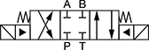
Single-Action Electrically Operated Air Directional Control Valves with Full Shut-Off
 |
Also known as 3-way and 3/3 valves, these valves close all ports in the off position to stop equipment in a locked position with air pressure holding it in place. They create one action, such as extending a cylinder. Apply voltage to the electrical connection to actuate. Valves direct airflow from the inlet to your equipment and exhaust return airflow to create motion. They're normally closed to block airflow until actuated. Return actuation is by spring, so they go back to their starting position as soon as voltage is removed.
Flow Coefficient (Cv)—Flow coefficient (Cv) is a measurement that indicates how much airflow can pass through a valve. When selecting between valves with the same port size, choose the valve with the higher flow coefficient to ensure it provides enough airflow to operate your system.
Overall | |||||||||||||||||||
|---|---|---|---|---|---|---|---|---|---|---|---|---|---|---|---|---|---|---|---|
No. of Flow Ports | Inlet Size | Outlet Size | Exhaust Connection | Max. Flow Rate @ 100 psi, scfm | Flow Coefficient (Cv) | Pressure Range, psi | Vacuum Rating, in. Hg | Voltage | Specs. Met | Lg. | Wd. | Ht. | Mount Type | Mounting Fasteners Included | Mounting Hole Dia. | Each | |||
Threaded Female Inlet x Threaded Female Outlet | |||||||||||||||||||
Double Solenoid—Spring Return | |||||||||||||||||||
| 3 | 1/8 NPT | 1/8 NPT | Threaded | 27.36 | 0.59 | 29 to 102 | 26 | 24V DC | EN 175301-803 | 2 1/2" | 1 1/8" | 4 3/8" | Screw In | Yes | 0.11" | 2850N11 | 0000000 | ||
| 3 | 1/8 NPT | 1/8 NPT | Threaded | 27.4 | 0.59 | 29 to 102 | 26 | 120V AC | EN 175301-803 | 2 1/2" | 1 1/8" | 4 3/8" | Screw In | Yes | 0.11" | 2850N12 | 000000 | ||
| 3 | 1/4 NPT | 1/4 NPT | Threaded | 41.27 | 0.89 | 29 to 102 | 26 | 24V DC | EN 175301-803 | 2 1/2" | 1 1/8" | 4 3/8" | Screw In | Yes | 0.11" | 2850N14 | 000000 | ||
| 3 | 1/4 NPT | 1/4 NPT | Threaded | 41.27 | 0.89 | 29 to 102 | 26 | 120V AC | EN 175301-803 | 2 1/2" | 1 1/8" | 4 3/8" | Screw In | Yes | 0.11" | 2850N13 | 000000 | ||
| 3 | 3/8 NPT | 3/8 NPT | Threaded | 124 | 2.2 | 29 to 102 | 26 | 24V DC | EN 175301-803 | 3 1/8" | 1 3/8" | 5 3/8" | Screw In | Yes | 0.22" | 2850N15 | 000000 | ||
| 3 | 3/8 NPT | 3/8 NPT | Threaded | 124 | 2.2 | 29 to 102 | 26 | 120V AC | EN 175301-803 | 3 1/8" | 1 3/8" | 5 3/8" | Screw In | Yes | 0.22" | 2850N16 | 000000 | ||
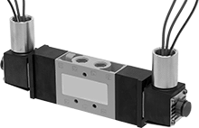
Single-Action Electrically Operated Air Directional Control Valves
 |  |  |
Style D | Style E | Style F |
Threaded Female Inlet × Threaded Female Outlet: Fail-Closed Valve
|
Style E |
Fail-closed valves block airflow until actuated.
Solenoid Return—Valves with solenoid return actuation go back to their original position when voltage is moved from the first solenoid to the second solenoid.
Flow Coefficient (Cv)—Flow coefficient (Cv) is a measurement that indicates how much airflow can pass through a valve. When selecting between valves with the same port size, choose the valve with the higher flow coefficient to ensure it provides enough airflow to operate your system.
Threaded Female Inlet × Threaded Female Outlet: Fail-Open Valve/Fail-Closed Valve
| |
Style D | Style F |
Valves that are both fail closed and fail open can be installed to block airflow, or allow air to flow until actuated.
Fail-closed valves block airflow until actuated.
Solenoid Return—Valves with solenoid return actuation go back to their original position when voltage is moved from the first solenoid to the second solenoid.
NPTF Inlet Thread—NPTF (Dryseal) threads are compatible with NPT threads.
Manifold Mount—Manifold-mount valves plug into a manifold (sold separately) to create multiple actions from a single pressure input. Manifolds with multiple exhaust ports have one set of inlet and exhaust ports on each side, so they can be strung together in a series. When using a single manifold, cover the ports on the side you are not using with plugs (sold separately).
Flow Coefficient (Cv)—Flow coefficient (Cv) is a measurement that indicates how much airflow can pass through a valve. When selecting between valves with the same port size, choose the valve with the higher flow coefficient to ensure it provides enough airflow to operate your system.
Valves | Replacement Solenoid Valve Plugs | |||||||||||||||||
|---|---|---|---|---|---|---|---|---|---|---|---|---|---|---|---|---|---|---|
Overall | ||||||||||||||||||
Style | No. of Flow Ports | Inlet Size | Outlet Size | Exhaust Connection | Max. Flow Rate @ 100 psi, scfm | Flow Coefficient (Cv) | Pressure Range, psi | Lg. | Wd. | Ht. | Mount Type | Choose a Voltage | Each | Each | ||||
Double Solenoid—Solenoid Return | ||||||||||||||||||
| D | 3 | 1/8 NPT | 1/8 NPT | Threaded | 24.9 | 0.75 | 29 to 145 | 6 1/4" | 7/8" | 1 3/8" | Manifold, Screw In | 24V DC, 120V AC | 6124K514 | 0000000 | 6124K301 | 00000 | ||
| D | 3 | 1/4 NPT | 1/4 NPT | Threaded | 24.9 | 1.3 | 29 to 145 | 7 1/16" | 1" | 1 5/8" | Manifold, Screw In | 24V DC, 120V AC | 6124K518 | 000000 | 6124K301 | 0000 | ||
| F | 3 | 3/8 NPTF | 3/8 NPTF | Threaded | 53.1 | 1.7 | 35 to 150 | 8 1/4" | 1 1/4" | 4 3/4" | Screw In | 24V DC, 120V AC | 6124K58 | 000000 | 6124K301 | 0000 | ||
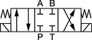
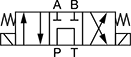
Solenoid-Operated Block-Mount Hydraulic Directional Control Valves
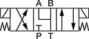
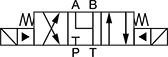
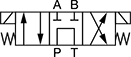
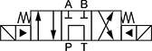
Double-Solenoid 4 Way Valves—3 Flow Positions (4/3 Valves)
 |  |  |  |
Style 3 | Style 4 | Style 5 | Style 6 |
 |  |  |  |
Style 7 | Style 8 | Style 9 | Style 10 |
 |  |  | |
D03 Mounting Pattern | D05 Mounting Pattern | D08 Mounting Pattern |
Valves | Screws | |||||||||||
|---|---|---|---|---|---|---|---|---|---|---|---|---|
Style | NFPA Mounting Pattern | ISO Mounting Pattern | Max. Flow Rate, gpm | Max. Pressure, psi | Choose a Voltage | Each | Pkg. Qty. | Pkg. | ||||
Default Position Closed | ||||||||||||
| 3 | D03 | 03 | 20 | 5,000 | 12V DC, 24V DC, 120V AC | 49995K5 | 0000000 | 4 | 1945N12 | 00000 | ||
| 3 | D05 | 05 | 40 | 5,000 | 12V DC, 24V DC, 120V AC | 49995K9 | 000000 | 4 | 1945N15 | 0000 | ||
| 4 | D08 | 08 | 160 | 5,000 | 12V DC, 24V DC, 120V AC | 49995K27 | 00000000 | 6 | 1945N18 | 00000 | ||
Default Position Open | ||||||||||||
| 5 | D03 | 03 | 20 | 5,000 | 12V DC, 24V DC, 120V AC | 49995K6 | 000000 | 4 | 1945N12 | 0000 | ||
| 5 | D05 | 05 | 40 | 5,000 | 12V DC, 24V DC, 120V AC | 49995K17 | 000000 | 4 | 1945N15 | 0000 | ||
| 6 | D08 | 08 | 160 | 5,000 | 12V DC, 24V DC, 120V AC | 49995K29 | 00000000 | 6 | 1945N18 | 00000 | ||
Default Position P Closed, A and B Open to T | ||||||||||||
| 7 | D03 | 03 | 10 | 5,000 | 12V DC, 24V DC, 120V AC | 49995K7 | 000000 | 4 | 1945N12 | 0000 | ||
| 7 | D05 | 05 | 40 | 5,000 | 12V DC, 24V DC, 120V AC | 49995K18 | 000000 | 4 | 1945N15 | 0000 | ||
| 8 | D08 | 08 | 160 | 5,000 | 12V DC, 24V DC, 120V AC | 49995K47 | 00000000 | 6 | 1945N18 | 00000 | ||
Default Position P Open to T, A and B Closed | ||||||||||||
| 9 | D03 | 03 | 15 | 5,000 | 12V DC, 24V DC, 120V AC | 49995K8 | 000000 | 4 | 1945N12 | 0000 | ||
| 9 | D05 | 05 | 10 | 5,000 | 12V DC, 24V DC, 120V AC | 49995K19 | 000000 | 4 | 1945N15 | 0000 | ||
| 10 | D08 | 08 | 80 | 5,000 | 12V DC, 24V DC, 120V AC | 49995K48 | 00000000 | 6 | 1945N18 | 00000 | ||
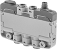
Modular Air Directional Control Valves with Air Manifolds
 |
Mount valves to a single-station base or to a manifold, which allows a single pressure source for multiple valves, then add or remove valves as your needs change. Valves with the same style can be used on the same manifold. For example, you can put a Style B, 2-position, spring-return valve and a Style B, 3-position, solenoid-return valve on the same manifold.
4-Way Valves
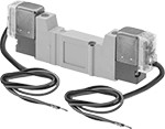 |
Double Solenoid Valve |
4-way valves create two actions, such as extending and then retracting a double-acting cylinder.
5/3 (Closed Center) Flow Pattern—5/3 (closed center) valves close all ports in the off position to stop equipment in a locked position with air pressure holding it in place.
5/3 (Exhaust Center) Flow Pattern—5/3 (exhaust center) valves exhaust all air pressure in the off position, allowing equipment to return to the neutral position.
5/3 (Pressure Center) Flow Pattern—5/3 (pressure center) valves create two actions at the same time, such as extending two single-acting cylinders at once.
Solenoid Return—Valves with solenoid return actuation go back to their original position when voltage is moved from the first solenoid to the second solenoid.
Flow Coefficient (Cv)—Flow coefficient (Cv) indicates how much airflow can pass through a valve.
Overall | ||||||||||||||||||
|---|---|---|---|---|---|---|---|---|---|---|---|---|---|---|---|---|---|---|
Style | No. of Valves | No. of Flow Ports | No. of Flow Positions | Max. Flow Rate @ 100 psi, scfm | Flow Coefficient (Cv) | Pressure Range, psi | Vacuum Rating | Wire Connection | Lg. | Wd. | Ht. | Body Material | Mounting Fasteners Included | Choose a Voltage | Each | |||
5/2 Flow Pattern | ||||||||||||||||||
Double Solenoid—Solenoid Return | ||||||||||||||||||
| B | 1 | 5 | 2 | 8 | 0.24 | 21 to 101 | Not Rated | Wire Leads | 3 1/2" | 3/8" | 1 1/8" | Zinc Alloy | Yes | 24V DC, 110V AC | 62165K84 | 000000 | ||
| C | 1 | 5 | 2 | 20 | 0.64 | 21 to 101 | Not Rated | Wire Leads | 4 1/4" | 5/8" | 1 1/8" | Aluminum | Yes | 24V DC, 110V AC | 62165K89 | 00000 | ||
| D | 1 | 5 | 2 | 35 | 1 | 21 to 101 | Not Rated | Wire Leads | 4 3/4" | 3/4" | 1 1/4" | Aluminum | Yes | 24V DC, 110V AC | 62165K95 | 00000 | ||
5/3 (Closed Center) Flow Pattern | ||||||||||||||||||
Double Solenoid—Solenoid Return | ||||||||||||||||||
| B | 1 | 5 | 3 | 6 | 0.18 | 29 to 101 | Not Rated | Wire Leads | 3 7/8" | 3/8" | 1 1/8" | Zinc Alloy | Yes | 24V DC, 110V AC | 62165K85 | 00000 | ||
| C | 1 | 5 | 3 | 15 | 0.47 | 29 to 101 | Not Rated | Wire Leads | 4 3/4" | 5/8" | 1 1/8" | Aluminum | Yes | 24V DC, 110V AC | 62165K91 | 00000 | ||
| D | 1 | 5 | 3 | 23 | 0.72 | 29 to 101 | Not Rated | Wire Leads | 5 1/4" | 3/4" | 1 1/4" | Aluminum | Yes | 24V DC, 110V AC | 62165K96 | 00000 | ||
5/3 (Exhaust Center) Flow Pattern | ||||||||||||||||||
Double Solenoid—Solenoid Return | ||||||||||||||||||
| B | 1 | 5 | 3 | 6 | 0.18 | 29 to 101 | Not Rated | Wire Leads | 3 7/8" | 3/8" | 1 1/8" | Zinc Alloy | Yes | 24V DC, 110V AC | 62165K86 | 00000 | ||
| C | 1 | 5 | 3 | 14 | 0.44 | 29 to 101 | Not Rated | Wire Leads | 4 3/4" | 5/8" | 1 1/8" | Aluminum | Yes | 24V DC, 110V AC | 62165K92 | 00000 | ||
| D | 1 | 5 | 3 | 23 | 0.71 | 29 to 101 | Not Rated | Wire Leads | 5 1/4" | 3/4" | 1 1/4" | Aluminum | Yes | 24V DC, 110V AC | 62165K97 | 00000 | ||
5/3 (Pressure Center) Flow Pattern | ||||||||||||||||||
Double Solenoid—Solenoid Return | ||||||||||||||||||
| B | 1 | 5 | 3 | 8 | 0.24 | 29 to 101 | Not Rated | Wire Leads | 3 7/8" | 3/8" | 1 1/8" | Zinc Alloy | Yes | 24V DC, 110V AC | 62165K87 | 00000 | ||
| C | 1 | 5 | 3 | 15 | 0.48 | 29 to 101 | Not Rated | Wire Leads | 4 3/4" | 5/8" | 1 1/8" | Aluminum | Yes | 24V DC, 110V AC | 62165K93 | 00000 | ||
| D | 1 | 5 | 3 | 20 | 0.63 | 29 to 101 | Not Rated | Wire Leads | 5 1/4" | 3/4" | 1 1/4" | Aluminum | Yes | 24V DC, 110V AC | 62165K98 | 00000 | ||
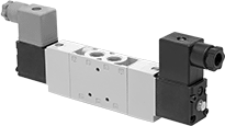
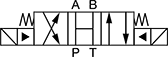
Simultaneous Two-Action Electrically Operated Air Directional Control Valves
 |
Also known as pressure-center valves and 4-way valves, these valves create two actions at the same time, such as extending two single-acting cylinders at once. Apply voltage to the electrical connection to actuate. They direct airflow from the inlet to your equipment and exhaust return airflow to create motion. Return actuation is electric (solenoid), so they go back to their original position when voltage moves from the first solenoid to the second solenoid.
Flow Coefficient (Cv)—Flow coefficient (Cv) indicates how much airflow can pass through a valve.
Overall | ||||||||||||||||
|---|---|---|---|---|---|---|---|---|---|---|---|---|---|---|---|---|
No. of Flow Ports | Inlet Size | Outlet Size | Exhaust Connection | Max. Flow Rate @ 100 psi, scfm | Flow Coefficient (Cv) | Pressure Range, psi | Vacuum Rating | Voltage | Lg. | Wd. | Ht. | Mounting Fasteners Included | Each | |||
5/3 (Pressure Center) Flow Pattern | ||||||||||||||||
Threaded Female Inlet x Threaded Female Outlet | ||||||||||||||||
| 5 | 1/8 NPT | 1/8 NPT | Threaded | 19 | 0.6 | 43 to 145 | Not Rated | 24V DC | 8 3/4" | 7/8" | 2 5/8" | Yes | 2945N21 | 0000000 | ||
| 5 | 1/8 NPT | 1/8 NPT | Threaded | 19 | 0.6 | 43 to 145 | Not Rated | 120V AC | 8 3/4" | 7/8" | 2 5/8" | Yes | 2945N22 | 000000 | ||
| 5 | 1/4 NPT | 1/4 NPT | Threaded | 48 | 1.5 | 43 to 145 | Not Rated | 24V DC | 9 1/4" | 7/8" | 2 5/8" | Yes | 2945N23 | 000000 | ||
| 5 | 1/4 NPT | 1/4 NPT | Threaded | 48 | 1.5 | 43 to 145 | Not Rated | 120V AC | 9 1/4" | 7/8" | 2 5/8" | Yes | 2945N24 | 000000 | ||
| 5 | 3/8 NPT | 3/8 NPT | Threaded | 79 | 2.5 | 43 to 145 | Not Rated | 24V DC | 10 3/4" | 1 1/8" | 2 3/4" | Yes | 2945N25 | 000000 | ||
| 5 | 3/8 NPT | 3/8 NPT | Threaded | 79 | 2.5 | 43 to 145 | Not Rated | 120V AC | 10 3/4" | 1 1/8" | 2 3/4" | Yes | 2945N26 | 000000 | ||
Electrically Operated Air Directional Control Valves with Flow Control
Push-to-Connect Male Inlet x Push-to-Connect Male Outlet
 |
Double Solenoid |
5/3 (Closed Center) Flow Pattern—5/3 (closed center) valves close all ports in the off position to stop equipment in a locked position with air pressure holding it in place.
5/3 (Pressure Center) Flow Pattern—5/3 (pressure center) valves create two actions at the same time, such as extending two single-acting cylinders at once.
Solenoid Return—Valves with solenoid return actuation go back to their original position when voltage is moved from the first solenoid to the second solenoid.
Flow Coefficient (Cv)—Flow coefficient (Cv) indicates how much airflow can pass through a valve.
Inlet | Outlet | Overall | ||||||||||||||||
|---|---|---|---|---|---|---|---|---|---|---|---|---|---|---|---|---|---|---|
No. of Flow Ports | For Tube OD | For Tube ID | For Tube ID | For Tube OD | Exhaust Connection | Max. Flow Rate @ 100 psi, scfm | Flow Coefficient (Cv) | Pressure Range, psi | Vacuum Rating | Lg. | Wd. | Ht. | Mounting Fasteners Included | Choose a Voltage | Each | |||
5/2 Flow Pattern | ||||||||||||||||||
Double Solenoid—Solenoid Return | ||||||||||||||||||
| 5 | 1/4" | 11/64" | 11/64" | 1/4" | Threaded | 24.7 | 0.7 | 20 to 150 | Not Rated | 7 3/8" | 1 3/8" | 2 3/4" | No | 24V DC, 120V AC | 4666A5 | 0000000 | ||
| 5 | 3/8" | 1/4" | 1/4" | 3/8" | Threaded | 24.7 | 0.7 | 20 to 150 | Not Rated | 7 3/8" | 1 3/8" | 2 3/4" | No | 24V DC, 120V AC | 4666A1 | 000000 | ||
5/3 (Closed Center) Flow Pattern | ||||||||||||||||||
Double Solenoid—Solenoid Return | ||||||||||||||||||
| 5 | 1/4" | 11/64" | 11/64" | 1/4" | Threaded | 24.7 | 0.7 | 20 to 150 | Not Rated | 7 3/8" | 1 3/8" | 2 3/4" | No | 24V DC, 120V AC | 4666A8 | 000000 | ||
| 5 | 3/8" | 1/4" | 1/4" | 3/8" | Threaded | 24.7 | 0.7 | 20 to 150 | Not Rated | 7 3/8" | 1 3/8" | 2 3/4" | No | 24V DC, 120V AC | 4666A3 | 000000 | ||
5/3 (Pressure Center) Flow Pattern | ||||||||||||||||||
Double Solenoid—Solenoid Return | ||||||||||||||||||
| 5 | 1/4" | 11/64" | 11/64" | 1/4" | Threaded | 24.7 | 0.7 | 20 to 150 | Not Rated | 7 3/8" | 1 3/8" | 2 3/4" | No | 24V DC, 120V AC | 4666A9 | 000000 | ||
| 5 | 3/8" | 1/4" | 1/4" | 3/8" | Threaded | 24.7 | 0.7 | 20 to 150 | Not Rated | 7 3/8" | 1 3/8" | 2 3/4" | No | 24V DC, 120V AC | 4666A4 | 000000 | ||
Wear-Resistant Electrically Operated Air Directional Control Valves
Threaded Female Inlet x Threaded Female Outlet
 |
Double Solenoid |
5/3 (Closed Center) Flow Pattern—5/3 (closed center) valves close all ports in the off position to stop equipment in a locked position with air pressure holding it in place.
Solenoid Return—Valves with solenoid return actuation go back to their original position when voltage is moved from the first solenoid to the second solenoid.
Flow Coefficient (Cv)—Flow coefficient (Cv) indicates how much airflow can pass through a valve.
Overall | ||||||||||||||||
|---|---|---|---|---|---|---|---|---|---|---|---|---|---|---|---|---|
No. of Flow Ports | Inlet Size | Outlet Size | Exhaust Connection | Max. Flow Rate @ 100 psi, scfm | Flow Coefficient (Cv) | Pressure Range, psi | Vacuum Rating, in. Hg | Voltage | Lg. | Wd. | Ht. | Mounting Fasteners Included | Each | |||
5/2 Flow Pattern | ||||||||||||||||
Double Solenoid—Solenoid Return | ||||||||||||||||
| 5 | 1/4 NPT | 1/4 NPT | Threaded | 40 | 1.1 | 29 to 150 | 24 | 24V DC | 7" | 1 7/8" | 5 3/4" | Yes | 4117N17 | 0000000 | ||
| 5 | 1/4 NPT | 1/4 NPT | Threaded | 40 | 1.1 | 29 to 150 | 24 | 120V AC | 7" | 1 7/8" | 5 3/4" | Yes | 4117N15 | 000000 | ||
| 5 | 3/8 NPT | 3/8 NPT | Threaded | 40 | 1.1 | 29 to 150 | 24 | 24V DC | 7" | 1 7/8" | 6" | Yes | 4117N18 | 000000 | ||
| 5 | 3/8 NPT | 3/8 NPT | Threaded | 40 | 1.1 | 29 to 150 | 24 | 120V AC | 7" | 1 7/8" | 6" | Yes | 4117N16 | 000000 | ||
5/3 (Closed Center) Flow Pattern | ||||||||||||||||
Double Solenoid—Solenoid Return | ||||||||||||||||
| 5 | 1/4 NPT | 1/4 NPT | Threaded | 40 | 1.1 | 44 to 150 | 24 | 24V DC | 7" | 1 7/8" | 5 3/4" | Yes | 4117N13 | 000000 | ||
| 5 | 1/4 NPT | 1/4 NPT | Threaded | 40 | 1.1 | 44 to 150 | 24 | 120V AC | 7" | 1 7/8" | 6" | Yes | 4117N11 | 000000 | ||
| 5 | 3/8 NPT | 3/8 NPT | Threaded | 40 | 1.1 | 44 to 150 | 24 | 24V DC | 7" | 1 7/8" | 6" | Yes | 4117N14 | 000000 | ||
| 5 | 3/8 NPT | 3/8 NPT | Threaded | 40 | 1.1 | 44 to 150 | 24 | 120V AC | 7" | 1 7/8" | 6" | Yes | 4117N12 | 000000 | ||
Hazardous Location Electrically Operated Air Directional Control Valves
Threaded Female Inlet × Threaded Female Outlet—Threaded Exhaust
 |
Double Solenoid |
5/3 (Closed Center) Flow Pattern—5/3 (closed center) valves close all ports in the off position to stop equipment in a locked position with air pressure holding it in place.
Flow Coefficient (Cv)—Flow coefficient (Cv) indicates how much airflow can pass through a valve.
Hazardous Location Rating—Hazardous location ratings indicate whether manufacturers have included safety features in products to facilitate their safe use in a hazardous environment. Before selecting a product for a hazardous location, ensure it is rated for your environment.
Overall | ||||||||||||||||||
|---|---|---|---|---|---|---|---|---|---|---|---|---|---|---|---|---|---|---|
No. of Flow Ports | Inlet Size | Outlet Size | Max. Flow Rate @ 100 psi, scfm | Flow Coefficient (Cv) | Pressure Range, psi | Vacuum Rating, in. Hg | Hazardous Location Rating | Enclosure Rating | Voltage | Wire Connection | Lg. | Wd. | Ht. | Mounting Fasteners Included | Each | |||
5/3 (Closed Center) Flow Pattern | ||||||||||||||||||
Double Solenoid | ||||||||||||||||||
| 5 | 1/4 NPT | 1/4 NPT | 65.34 | 1.7 | 14 to 145 | 28 | NEC Class I Divisions 1, 2 Groups A, B, C, D NEC Class II Divisions 1, 2 Groups E, F, G | NEMA 3S NEMA 6P NEMA 7 NEMA 9 | 24V DC | Wire Leads | 9 3/8" | 1" | 2 7/8" | No | 2992N13 | 0000000 | ||
| 5 | 1/4 NPT | 1/4 NPT | 65.34 | 1.7 | 14 to 145 | 28 | NEC Class I Divisions 1, 2 Groups A, B, C, D NEC Class II Divisions 1, 2 Groups E, F, G | NEMA 3S NEMA 6P NEMA 7 NEMA 9 | 120V AC | Wire Leads | 9 3/8" | 1" | 2 7/8" | No | 2992N14 | 000000 | ||
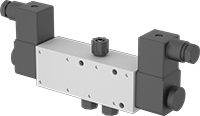
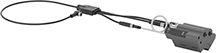
Robot-Arm-Mounted Electrically Operated Air Directional Control Valves
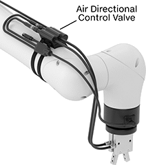 | |
Control air-powered robot tools, such as pick-and-place grippers. These valves have two three-way valves, also known as 3/2 valves, that you can control separately with your robot’s program. For example, you can connect two single-acting tools, such as two grippers with spring jaw returns, using one valve for each. Alternatively, use both valves for one double-acting tool, such as an air cylinder—one valve pushes the cylinder out, the other pulls it back. In both setups, air escapes through vents on the side of the manifold.
These valves come with everything you need for quick installation. Use the hook and loop straps to mount them to your robot arm, then plug the electrical cord into the M8 connection at the end of the arm. Connect your compressed air line to the inlet. Last, run tubing from the valve to your robot tool.
Inlet | Outlet | |||||||||
|---|---|---|---|---|---|---|---|---|---|---|
No. of Flow Ports | Connection | For Tube OD, mm | Connection | For Tube OD, mm | Max. Flow Rate @ Pressure | Flow Coefficient (Cv) | Pressure Range, psi | Each | ||
| 3 | Push to Connect | 6 | Push to Connect | 6 | 2 scfm @ 80 psi | 0.09 | 0 to 100 | 9015N11 | 0000000 | |
Screw-In Hydraulic Directional-Control Valves
Double-Solenoid 4 Way Valves—3 Flow Positions (4/3 Valves)
 |
 |
Style 4 |
 |
Style 5 |
Place four-way valves between the pressure source and a double-acting cylinder.
Valves | Replacement Solenoid Coils | ||||||||||||
|---|---|---|---|---|---|---|---|---|---|---|---|---|---|
Body—UN/UNF (SAE Straight) | |||||||||||||
Deltrol Equivalent Model No. | Hydraforce Equivalent Model No. | Thread Size | Dash Size | Max. Flow Rate, gpm | Max. Pressure, psi | Voltage, V DC | Overall Ht. | Each | Each | ||||
Style 4—Default Position Closed | |||||||||||||
| DSV-080-34C-N-D1DE | SV08-47C-0-N-12EL | 3/4"-16 | 08 | 3 | 3,000 | 12 | 5 1/2" | 1643N62 | 0000000 | 1678N11 | 000000 | ||
Style 5—Default Position P Open to T, A and B Closed | |||||||||||||
| DSV-080-34T-N-D1DE | SV08-47A-0-N-12EL | 3/4"-16 | 08 | 3 | 3,000 | 12 | 5 1/2" | 1643N78 | 000000 | 1678N11 | 00000 | ||
| DSV-080-34T-N-D2DE | SV08-47A-0-N-24EL | 3/4"-16 | 08 | 3 | 3,000 | 24 | 5 1/2" | 1643N79 | 000000 | 1678N12 | 00000 | ||
High-Pressure Washdown Electrically Operated Air Directional Control Valves
Threaded Female Inlet × Threaded Female Outlet—Threaded Exhaust
 |
Solenoid Return—Valves with solenoid return actuation go back to their original position when voltage is moved from the first solenoid to the second solenoid.
4 Way—4-way valves create two actions, such as extending and then retracting a double-acting cylinder.
2 Exhaust Ports—Valves with two exhaust ports allow you to independently control the speed of two different actions. Connect a flow control valve to each exhaust port.
Flow Coefficient (Cv)—Flow coefficient (Cv) indicates how much airflow can pass through a valve.
Overall, mm | |||||||||||||||
|---|---|---|---|---|---|---|---|---|---|---|---|---|---|---|---|
Air Directional Control Valve Type | Air Directional Control Valve Flow Pattern | No. of Flow Ports | No. of Exhaust Ports | Max. Flow Rate @ 100 psi, scfm | Flow Coefficient (Cv) | Pressure Range, psi | Vacuum Rating, in. Hg | Voltage, V DC | Lg. | Wd. | Ht. | Each | |||
Double Solenoid—Solenoid Return | |||||||||||||||
| 4 Way | 5/2 | 5 | 2 | 25.11 | 0.711 | -13 to 145 | 26.5 | 24 | 190.5 | 34.9 | 68.58 | 2963N15 | 0000000 | ||
Push-to-Connect Female Inlet × Push-to-Connect Female Outlet—Push-to-Connect Exhaust
|
Solenoid Return—Valves with solenoid return actuation go back to their original position when voltage is moved from the first solenoid to the second solenoid.
4 Way—4-way valves create two actions, such as extending and then retracting a double-acting cylinder.
2 Exhaust Ports—Valves with two exhaust ports allow you to independently control the speed of two different actions. Connect a flow control valve to each exhaust port.
Flow Coefficient (Cv)—Flow coefficient (Cv) indicates how much airflow can pass through a valve.
Overall, mm | |||||||||||||||||
|---|---|---|---|---|---|---|---|---|---|---|---|---|---|---|---|---|---|
Air Directional Control Valve Type | Air Directional Control Valve Flow Pattern | No. of Flow Ports | No. of Exhaust Ports | For Inlet Tube OD, mm | For Outlet Tube OD, mm | Max. Flow Rate @ 100 psi, scfm | Flow Coefficient (Cv) | Pressure Range, psi | Vacuum Rating, in. Hg | Voltage, V DC | Lg. | Wd. | Ht. | Each | |||
Double Solenoid—Solenoid Return | |||||||||||||||||
| 4 Way | 5/2 | 5 | 2 | 8 | 8 | 25.11 | 0.711 | -13 to 145 | 26.5 | 24 | 190.5 | 34.9 | 76.2 | 2963N16 | 0000000 | ||
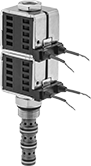
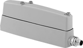
Robot-Arm-Mounted Electrically Operated Air On/Off Valves
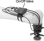 |  |
Control the flow of air to robot tools from your robot's program. Often used with air-powered vacuum lifters, these electrically controlled valves open to supply air to the lifter, generating suction to pick up a part. When these valves close, the suction stops and the part drops. An integrated switch monitors the tool’s vacuum level via analog signals, so you know if a part was successfully picked. A built-in LED display shows the vacuum status and lets you change vacuum setpoints.
These valves come with everything you need for quick installation. Use the hook and loop straps to mount them to your robot arm, then plug the electrical cord into the M8 connection at the end of the arm. Connect your compressed air line to the inlet. Last, run tubing from the valve to your robot tool.
Rapid Part Release—Valves with rapid part release can send a burst of air to push a part off your vacuum lifter, so you don’t have to wait for it to drop. They’re often used for pick-and-place applications requiring high speed and precision.
Inlet | Outlet | Overall | |||||||||||
|---|---|---|---|---|---|---|---|---|---|---|---|---|---|
Max. Pressure, psi | Flow Coefficient (Cv) | Max. Flow Rate @ 80 psi, scfm | Connection | For Tube OD, mm | Connection | For Tube OD, mm | Temp. Range, ° F | Lg. | Ht. | Each | |||
Valves with Rapid Part Release and Vacuum Monitoring | |||||||||||||
| 100 | 0.24 | 6 | Push to Connect | 6 | Push to Connect | 6 | 35 to 120 | 3 1/2" | 4 1/8" | 8880N11 | 0000000 | ||
